EP1256358B1 - Infusion set for drug delivery - Google Patents
Infusion set for drug delivery Download PDFInfo
- Publication number
- EP1256358B1 EP1256358B1 EP01111331A EP01111331A EP1256358B1 EP 1256358 B1 EP1256358 B1 EP 1256358B1 EP 01111331 A EP01111331 A EP 01111331A EP 01111331 A EP01111331 A EP 01111331A EP 1256358 B1 EP1256358 B1 EP 1256358B1
- Authority
- EP
- European Patent Office
- Prior art keywords
- infusion device
- needle
- cannula
- claw
- elements
- Prior art date
- Legal status (The legal status is an assumption and is not a legal conclusion. Google has not performed a legal analysis and makes no representation as to the accuracy of the status listed.)
- Expired - Lifetime
Links
- 238000001802 infusion Methods 0.000 title claims abstract description 59
- 238000012377 drug delivery Methods 0.000 title 1
- 210000000078 claw Anatomy 0.000 claims abstract description 91
- 241001465754 Metazoa Species 0.000 claims abstract description 8
- 238000003780 insertion Methods 0.000 claims description 21
- 230000037431 insertion Effects 0.000 claims description 21
- 230000001225 therapeutic effect Effects 0.000 claims description 9
- 238000002347 injection Methods 0.000 claims description 8
- 239000007924 injection Substances 0.000 claims description 8
- 239000004033 plastic Substances 0.000 claims description 7
- 229920003023 plastic Polymers 0.000 claims description 7
- 238000000034 method Methods 0.000 claims description 5
- 230000008569 process Effects 0.000 claims description 5
- 239000000126 substance Substances 0.000 claims 5
- 229920006324 polyoxymethylene Polymers 0.000 claims 2
- 229930182556 Polyacetal Natural products 0.000 claims 1
- 239000004035 construction material Substances 0.000 claims 1
- 238000011144 upstream manufacturing Methods 0.000 claims 1
- 239000003814 drug Substances 0.000 abstract description 17
- 239000000463 material Substances 0.000 description 11
- 238000004519 manufacturing process Methods 0.000 description 10
- 229940124597 therapeutic agent Drugs 0.000 description 10
- 210000003811 finger Anatomy 0.000 description 6
- 230000001590 oxidative effect Effects 0.000 description 4
- 230000009286 beneficial effect Effects 0.000 description 3
- 230000008901 benefit Effects 0.000 description 3
- 238000013461 design Methods 0.000 description 3
- 230000005489 elastic deformation Effects 0.000 description 3
- 244000005700 microbiome Species 0.000 description 3
- 230000001954 sterilising effect Effects 0.000 description 3
- 210000003813 thumb Anatomy 0.000 description 3
- 210000003462 vein Anatomy 0.000 description 3
- 238000010276 construction Methods 0.000 description 2
- 229940079593 drug Drugs 0.000 description 2
- 230000002708 enhancing effect Effects 0.000 description 2
- NOESYZHRGYRDHS-UHFFFAOYSA-N insulin Chemical compound N1C(=O)C(NC(=O)C(CCC(N)=O)NC(=O)C(CCC(O)=O)NC(=O)C(C(C)C)NC(=O)C(NC(=O)CN)C(C)CC)CSSCC(C(NC(CO)C(=O)NC(CC(C)C)C(=O)NC(CC=2C=CC(O)=CC=2)C(=O)NC(CCC(N)=O)C(=O)NC(CC(C)C)C(=O)NC(CCC(O)=O)C(=O)NC(CC(N)=O)C(=O)NC(CC=2C=CC(O)=CC=2)C(=O)NC(CSSCC(NC(=O)C(C(C)C)NC(=O)C(CC(C)C)NC(=O)C(CC=2C=CC(O)=CC=2)NC(=O)C(CC(C)C)NC(=O)C(C)NC(=O)C(CCC(O)=O)NC(=O)C(C(C)C)NC(=O)C(CC(C)C)NC(=O)C(CC=2NC=NC=2)NC(=O)C(CO)NC(=O)CNC2=O)C(=O)NCC(=O)NC(CCC(O)=O)C(=O)NC(CCCNC(N)=N)C(=O)NCC(=O)NC(CC=3C=CC=CC=3)C(=O)NC(CC=3C=CC=CC=3)C(=O)NC(CC=3C=CC(O)=CC=3)C(=O)NC(C(C)O)C(=O)N3C(CCC3)C(=O)NC(CCCCN)C(=O)NC(C)C(O)=O)C(=O)NC(CC(N)=O)C(O)=O)=O)NC(=O)C(C(C)CC)NC(=O)C(CO)NC(=O)C(C(C)O)NC(=O)C1CSSCC2NC(=O)C(CC(C)C)NC(=O)C(NC(=O)C(CCC(N)=O)NC(=O)C(CC(N)=O)NC(=O)C(NC(=O)C(N)CC=1C=CC=CC=1)C(C)C)CC1=CN=CN1 NOESYZHRGYRDHS-UHFFFAOYSA-N 0.000 description 2
- 230000005865 ionizing radiation Effects 0.000 description 2
- 238000007391 self-medication Methods 0.000 description 2
- 239000000243 solution Substances 0.000 description 2
- 238000004659 sterilization and disinfection Methods 0.000 description 2
- VGGSQFUCUMXWEO-UHFFFAOYSA-N Ethene Chemical compound C=C VGGSQFUCUMXWEO-UHFFFAOYSA-N 0.000 description 1
- 239000005977 Ethylene Substances 0.000 description 1
- 206010018852 Haematoma Diseases 0.000 description 1
- 102000004877 Insulin Human genes 0.000 description 1
- 108090001061 Insulin Proteins 0.000 description 1
- 230000004888 barrier function Effects 0.000 description 1
- 239000003795 chemical substances by application Substances 0.000 description 1
- 238000004140 cleaning Methods 0.000 description 1
- 230000001143 conditioned effect Effects 0.000 description 1
- 239000000356 contaminant Substances 0.000 description 1
- 238000011109 contamination Methods 0.000 description 1
- 230000006735 deficit Effects 0.000 description 1
- 201000010099 disease Diseases 0.000 description 1
- 208000037265 diseases, disorders, signs and symptoms Diseases 0.000 description 1
- 238000004870 electrical engineering Methods 0.000 description 1
- 210000005224 forefinger Anatomy 0.000 description 1
- 230000006870 function Effects 0.000 description 1
- 238000001746 injection moulding Methods 0.000 description 1
- 229940125396 insulin Drugs 0.000 description 1
- 238000005304 joining Methods 0.000 description 1
- 239000007788 liquid Substances 0.000 description 1
- 230000007257 malfunction Effects 0.000 description 1
- 230000007935 neutral effect Effects 0.000 description 1
- 239000004417 polycarbonate Substances 0.000 description 1
- 229920000515 polycarbonate Polymers 0.000 description 1
- 238000007789 sealing Methods 0.000 description 1
- 230000035807 sensation Effects 0.000 description 1
- 238000003892 spreading Methods 0.000 description 1
- 230000007480 spreading Effects 0.000 description 1
- 210000002105 tongue Anatomy 0.000 description 1
- 238000012546 transfer Methods 0.000 description 1
Images


Classifications
-
- A—HUMAN NECESSITIES
- A61—MEDICAL OR VETERINARY SCIENCE; HYGIENE
- A61M—DEVICES FOR INTRODUCING MEDIA INTO, OR ONTO, THE BODY; DEVICES FOR TRANSDUCING BODY MEDIA OR FOR TAKING MEDIA FROM THE BODY; DEVICES FOR PRODUCING OR ENDING SLEEP OR STUPOR
- A61M5/00—Devices for bringing media into the body in a subcutaneous, intra-vascular or intramuscular way; Accessories therefor, e.g. filling or cleaning devices, arm-rests
- A61M5/14—Infusion devices, e.g. infusing by gravity; Blood infusion; Accessories therefor
- A61M5/158—Needles for infusions; Accessories therefor, e.g. for inserting infusion needles, or for holding them on the body
- A61M2005/1587—Needles for infusions; Accessories therefor, e.g. for inserting infusion needles, or for holding them on the body suitable for being connected to an infusion line after insertion into a patient
-
- A—HUMAN NECESSITIES
- A61—MEDICAL OR VETERINARY SCIENCE; HYGIENE
- A61M—DEVICES FOR INTRODUCING MEDIA INTO, OR ONTO, THE BODY; DEVICES FOR TRANSDUCING BODY MEDIA OR FOR TAKING MEDIA FROM THE BODY; DEVICES FOR PRODUCING OR ENDING SLEEP OR STUPOR
- A61M25/00—Catheters; Hollow probes
- A61M25/01—Introducing, guiding, advancing, emplacing or holding catheters
- A61M25/06—Body-piercing guide needles or the like
- A61M25/0612—Devices for protecting the needle; Devices to help insertion of the needle, e.g. wings or holders
-
- A—HUMAN NECESSITIES
- A61—MEDICAL OR VETERINARY SCIENCE; HYGIENE
- A61M—DEVICES FOR INTRODUCING MEDIA INTO, OR ONTO, THE BODY; DEVICES FOR TRANSDUCING BODY MEDIA OR FOR TAKING MEDIA FROM THE BODY; DEVICES FOR PRODUCING OR ENDING SLEEP OR STUPOR
- A61M39/00—Tubes, tube connectors, tube couplings, valves, access sites or the like, specially adapted for medical use
- A61M39/10—Tube connectors; Tube couplings
- A61M39/1011—Locking means for securing connection; Additional tamper safeties
-
- A—HUMAN NECESSITIES
- A61—MEDICAL OR VETERINARY SCIENCE; HYGIENE
- A61M—DEVICES FOR INTRODUCING MEDIA INTO, OR ONTO, THE BODY; DEVICES FOR TRANSDUCING BODY MEDIA OR FOR TAKING MEDIA FROM THE BODY; DEVICES FOR PRODUCING OR ENDING SLEEP OR STUPOR
- A61M39/00—Tubes, tube connectors, tube couplings, valves, access sites or the like, specially adapted for medical use
- A61M39/10—Tube connectors; Tube couplings
- A61M39/14—Tube connectors; Tube couplings for connecting tubes having sealed ends
Definitions
- the invention relates to an infusion device for the Administration of a therapeutic agent into the body of a human or an animal, comprising at least a first element on which a cannula for insertion into the interior of the body and the seat inside the body arranged is, and a second element, which is a needle with a continuous cavity in the manner of an injection needle having, with a hose element for the Supply of the therapeutic agent is connected, with the first and the second element via a locking element releasably are connected to each other such that the therapeutic from the tubing over the needle into the cannula can get.
- connection attempt does not lead to each other a desired connection or Verrastungsterrorism, if the first element is opposite to the second element even slightly laterally displaced, because next the local locking elements also two in the same Level arranged guide elements in register on the Guiding openings to be aligned in the other element need to make a latching insertion of both elements to be able to cause each other at all.
- the object is achieved according to the invention in that the locking element by a substantially circular ring circumferential groove of the substantially axially symmetric to the needle formed second element and by a substantially orthogonal in the connection state led to the second element in the first element reciprocally displaceable jaw member, in the connection state engaging both elements in the groove holds both elements locked together, trained becomes.
- the advantage of the solution according to the invention consists in essential in that, as desired, a simple Insert the second element into the first element is possible without a rotationally correct or in lateral direction of the two elements to each other proper alignment must be chosen.
- the second Element needs in the literal sense only in a corresponding single opening in the first element how to put this into coaxial plugs in the field of electrical engineering or electronics knows.
- a rotationally correct orientation is not required.
- Are both elements not axially to each other properly aligned, can also be no malfunction because the second element will not be not even with any pin and locking elements, the known device has four of the second Element projecting to be introduced incorrectly can.
- the locking element itself needs when merging and locking both elements not actuated at all whereas for unlocking it is merely e.g.
- second element is a substantially circular Cross-section on, in which the circular axis or the center of the circle coincides with the axis of the needle.
- the circumferential bevel also has the function that in that the claw member by the skew with axial insertion of the second element in the Entry hole is pushed apart, the spread the claw leg takes place, i. the bevel acts as an inclined plane for the spreading process of the claw legs.
- the entrance hole of the first element may be in its outer edge area, for example be formed bevelled widening, so for example a funnel-shaped insertion opening to build.
- the jaw member is preferably separated by two Claw legs formed essentially parallel to each other out to each other or from each other are wegbewegbar. In the course of the succession movement becomes the entrance hole of the first element unlocked, leaving the second element in the entry hole pushed in to a predetermined end position can be, whereas in the course of the Vonchrowegterrorism the claw legs of the claw element the second element in the first element releasably lockable is held.
- the claw legs have a circular section area corresponding to a radius the radius of the groove of the second element, with which he intervenes locking in the groove.
- the circular section-shaped Range is preferred in this case approximately quarter-circular, both quarter-circular Areas of the two claw legs together a semicircular, circular section-shaped Make the area with which in the locked position the second element can be held securely.
- the Infusion device is the guide for the jaw element or the claw legs substantially orthogonal to the axis of the substantially circular cross-section Entry hole formed for the second element.
- the infusion device is also operational Right-handed or left-handed or right-handed operation and Left hand operation par excellence, since the Claw element forming two claw legs due their essentially identical structure and theirs Arrangement and its displaceability symmetrical to Axle, arranged axially symmetrical to the cannula is and also the same course of motion of the Claw legs when locking and unlocking the second element is achieved, regardless of whether the both claw legs with the fingers of the right hand or the fingers of the left hand.
- the Claw leg preferably a locking lug, with the They behind latching projections, which are in the field of leadership or the guide slot formed in the first element are latching in the manner of a clip connection. There are therefore no further measures required to to hold the claw legs in the guide slot, after the claw legs with the assembly once with their locking lugs behind the locking projections in the guide slot have come to rest.
- the free element of the locking element may preferably be provided with a handle, for example, in Form of a widening of the body of the first Be formed element protruding jaw member can.
- the handle makes it easier for the user Device to operate the claw element more conveniently, it may be advantageous that thereby also the Handle additionally guided in the first element is taken, whereby the overall leadership of the Claw element in the first element to be improved can.
- the handle advantageously on its operating side a handle-improving Means, for example in the form of creases, Ridges, a dull surface or the like.
- a handle-improving agent it is beneficial to the Handle opposite side of the first element at least partially with a handle-improving agent to be provided so that when, for example, between Thumb and fingers the handle or the claw element and the first element is seized, a secure fit or a secure grasp with, for example, thumb and finger is guaranteed.
- the Invention has the second element at its free end a substantially axial recess, wherein preferably the needle with its pointed area into the depression in such a way that it passes over the free end of the second element does not protrude. So is continually assuring that upon insertion of the second element in the entrance hole of the first element no contact of the needle by the user can be done so that contamination with dirt and Microorganisms are always avoided and none mechanical damage to this area of the needle can happen, which is in the axial depression, so that a continuous precise axial alignment to the opening area of the cannula in the first element is guaranteed.
- the cannula is the infusion device preferably designed so that in each other connected and locked state of both elements the element-side opening area of the cannula at least partially protruding into the depression. This ensures that even if the material of both elements in certain areas is elastically deformable or due external influences is also slightly deformed, that continually the mandatory axial alignment between the tip of the needle and the opening area the cannula is reached.
- Another advantageous embodiment of Device for ensuring the seal to the outside Area between the opening of the cannula and the opening in the needle point is achieved in that the opening area with a covering this closure element is provided when inserting the needle in the Opening area, i. when inserting the second element into the entrance hole of the first element, pierced is or is if the intended seat Both elements is reached to each other, in which the mutual locking position is taken.
- Closure element preferably made of an elastomeric and / or plastic material, whereby can be achieved, that on the one hand the needle easily penetrate such trained closure element can and on the other hand after pulling out the needle due to the elastic or plastic properties the material of the closure element by the Needle created passage opening closed again becomes.
- the essential elements of the infusion device i. at least the first and the second element and the Locking element, can be made of plastic, for which any plastics are suitable, the harmless to human and veterinary medicine or neutral are.
- these materials are sprayable Materials, so that the infusion device advantageously produced by plastic injection molding machines can be.
- a material is suitable, for example Polycarbonate good.
- the claw element made of polyacetate POM because this material with great stability very good elastic deformation properties having.
- the cannula can in principle during manufacture of the first Elements in the course of the injection process in the first element be fixed or firmly connected to this.
- the cannula lie on her in the first element surrounding cannula end with a sleeve element, over that the cannula in one at the end of the entrance hole trained like a blind hole for the second element Opening is included in the first element.
- the first element independent of the cannula be made and there is a possibility that separately manufactured cannula over the sleeve element then about insertion in the blind hole-like opening with the first element to connect. This is for example also for replacement and / or cleaning purposes of the cannula of great advantage.
- the opening has a suitably designed Seat, preferably a press fit, for the Sleeve element forms.
- closure element through the needle when inserted second element passes through or that is a dust-tight or a microorganism density or against other contaminants dense barrier forms when the second element with its needle does not pass through the closure element, to arrange in the sleeve element itself. Consequently can also be done by simply replacing the cannula at the same time also the closure element in case of damage or other impairments and in the course the use of a new cannula to be replaced.
- a connecting element be about that the cannula with the sleeve element connected is.
- the connecting element in addition to the Closing element be arranged the connecting element, and it is in the sleeve before also the cannula over added the connecting element.
- the second element is in modified Embodiment provided with such a long needle, so that these in the locked state of the first and second element from the outlet of the administered Therapeutic usually topped the cannula protrudes.
- the cannula with the needle then introduced into the body, that's how it is modified second element pulled out and the second Element in the basic design described above with the cavity-shaped needle for feeding a Therapeuticum is in the manner described above in the first element inserted and in the end position locked way described above.
- the infusion device may take the form of its individual, sterilized separate elements or but also in the assembled state, and with ionizing radiation, for example ⁇ -rays. It is also possible, a sterilization by means of a oxidizing gas, such as ethylene gas to make.
- a sterilization by means of a oxidizing gas such as ethylene gas to make.
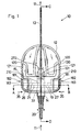
- the Infusion device 10 comprises at least a first Element 12, to which a cannula 13 for insertion into the Body interior of a user (human, animal) (not shown), and a second element 14.
- the second element 14 has a needle 15 which essentially in the longitudinal axis 20 of the second element 14 is arranged.
- the needle 15 is on itself known manner with an axially passing cavity provided, i. in the manner of a known injection needle educated.
- the needle 15 is in the second element 14 with a tube member 17 for the delivery of a therapeutic agent connected, wherein the supply in Fig. 1 by the arrow 11 is indicated.
- the locking element comprises in addition to the jaw member 22 a at substantially rotationally symmetrical and in cross section circular shaped second element 14th formed groove 19, see. in particular FIGS. 2 and 9 and indicated in Fig. 1.
- the groove 19 rotates around the second Element 14 is substantially circular.
- the groove 19 is in the region of the insertion section 23, cf. 6 and 7, formed, i. in the section of the second element 14, which in the locked state in the entry hole 33 of the first element 12 is located.
- the part of the detent element, i. the claw member 22, which is formed in the first element 12 is through a substantially orthogonal to the axis 32 of the entrance hole 33 trained guide 21 out, i. the Guide 21 can only be a simple slot-shaped Be deepening, cf. Fig. 1, in which the jaw element 22 is reciprocally displaceable, cf. Figs. 1 and 2.
- FIGS. 4a, 4b and 5a, 5b show the claw member 22, the the Part of the locking element forms, in the first element 12th is arranged.
- the jaw member 22 is replaced by two separate claw legs 26, 27 formed.
- the claw legs 26, 27 are basically identical, only those with the claw legs 26, 27 respectively connected handle 181, with the claw legs 26, 27 may be formed integrally, in the embodiment shown here with respect to the Illustration of Fig. 1 left version (claw leg 26) and form a right version (claw leg 27).
- the Claw legs 26, 27 have a circular section-shaped Range 263, 273 on. There is a circular section Area 263, 273 provided. The radius 28 this circular section-shaped region 263, 273 corresponds the radius 28, the groove 19 of the second element.
- the circular segment-shaped region 263, 273 is here formed approximately quarter-circular.
- On the claw legs 26, 27 are in the form of an inclined plane formed areas 261, 271 are provided, which are to the free ends 260, 270 taper towards or in relation fall to the inclined plane 261, 271.
- first element 12 cf. Fig. 2, are also provided as inclined plane formed areas 125, 126, namely in there as a guide slot 210th trained guide 21, see Figs. 1, 6 and 7.
- the claw legs 26, 27 are in the guide 21, 210th run parallel to each other and are in this in Direction of the arrow 35 towards each other movable and in opposite direction to the arrow 35 movable, wherein the movement against the direction of the arrows 25 due the elastic counterforce of the claw legs 26, 27 can be done automatically. So it needs for the Movement of the claw legs 26, 27 counter to the direction the arrows 35, the respective handles 181 only to be let go. As a result becomes independent the locking state of the claw legs 26, 27 and of the claw member 22 taken. Good elastic Deformation properties with great durability has, for example, polyacetate POM from which the Claw legs 26, 27 are preferably made.
- the claw legs 26, 27 also have a latching nose 262, 272, compare Figs. 4a, 5a and 2, on. With the Latches 262, 272 they engage behind locking projections 123, 124, in the region of the guide 21 in the first Element are formed, see Fig. 3.
- the locking lugs 262, 272 form together with the latching projections 123, 124 a clip connection which is entered, when the claw legs 26, 27 in the guide 21, 210th introduced during assembly with the first element 12 become.
- the locking lugs 262, 272 form next to one Attachment of the claw legs 26, 27 in the first element 12 also a movement limitation of the claw legs 26, 27 against the direction of the arrows 35, see FIG. Second
- Either the second element 14 is simply in the Entry hole 33 is inserted into it until it is free End 24 to the claw legs 26, 27, see. 2, encounters.
- the free end 24 is designed such that it has a circumferential chamfer 25.
- the bevel 25 is selected to engage the jaw legs 26 slightly grasp the leg inner sides 263, 273 can and in the course of movement of the second element 14 in the entry hole 33 in, the legs 26, 27 in Direction of the arrows 34 moves away from each other, as the Bevel 27 for the claw legs 26, 27 in this Trap forms an inclined plane. If you move on the front cylindrical part of the second element 14 when the second element 14 its constructive certain end position in the entry hole 33 of first element reaches 12, also the claw legs 26, 27 with the groove 19 curse, so that the claw legs 26, 27 latch into the groove 19 latch.
- the claw legs 26, 27 may slightly from the protrude first element 12 forming body, see. Fig. 1.
- a handle 180 is provided, wherein the handle 180, here in the form of a broadening of the Claw legs 26, 27 is formed in the first element 12 in the form of a likewise trained there leadership 210 can be performed.
- the handle 181 points at her Actuation side handle improving means 183, for example in the form of grooves or depressions, or it is there provided a non-slip element.
- the side 122 of the first element 12, cf. Fig. 2, the is to lie on the skin of a user is essentially flat and can also be ergonomic be shaped so that they are in the relevant Applizierungs Kunststoff the infusion device 10 am Body of the user can nestle, without negative Sensations on the part of the user during wearing cause the infusion device 10.
- the second element 14 has at its free end 24th a substantially axial recess 272, in the the needle 15 with its tip portion 150 in it.
- the protruding into the recess 172 tip area 150 is sized so that the needle 15 with her immediate tip does not have the free end 24 stands out, cf. 9 it can be seen from FIG. that the opening portion 130 of the cannula 13, the free end 24 of the second element 14 is directed, into the entry hole 33 in such a way that in locked state of the first and second elements 12, 13, the needle 15 in a front of the entrance hole 33 in the there widening opening of the cannula 13th arranged closure element 131 can penetrate. The Tip of the needle 15 then comes in the widened opening area the cannula 13, cf.
- Closure element 131 the guide means 133, see. Fig. 10, at its intended location before in Direction of the entrance hole 33 widening Opening portion 130 is seated, may be made of elastomeric and / or be formed polymeric material, for example Rubber or another suitable human or veterinary medicine harmless material.
- the cannula 13 is at its in the first element 12 to are coming cannula end 134, see Fig. 8, with surrounded a sleeve member 135.
- the closure element 131 is arranged and in the direction the exit-side end of the therapeutic agent 11 from the Cannula, i. in front of the closure element 131, is a Connecting element 137 is arranged, via which the cannula 13 is connected to the sleeve member 135.
- the cannula 13 and the sleeve member 135 and the recorded therein Closure element 131 and the connecting element 137 form a mounting unit, which in the first element 12 in the trained there in the bag-trained Opening 127 can be used.
- the opening 127 is preferably a press fit for the sleeve member 135 formed so that no further stop or Safety measures between the first element 12 and the sleeve member 135 must be provided.
- an obtuse angle in the range of 183 ° may be formed be so that the cannula 13 relative to the body of the first element 12 is inclined.
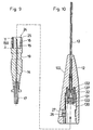
- second element 140 is different from the second element shown in the other figures 14 in that the second element 140 a very much longer needle 151 than the needle 15 has.
- the second Element 140 according to FIG. 7 is not with a hose element 17 for the supply of a therapeutic agent 11 connected, but there is the needle 151 to appropriate Way in the front region of the second element 140, i. the area with which the second element 140 on otherwise same way as described above, connected and becomes the same with the first element 12 connected like the second element 14.
- the needle 151 is so long that this in their top area 150th locked state of the first and second members 12, 140 from the normally to the outlet of the administered Therapeutics 11 specific tip of the cannula slightly protruding, see Fig. 7.
- the Needle 151 can easily enter the body in a known manner of the person or animal to be treated introduced during the introduction of the Needle 151 also the cannula 13 slightly into the body can be introduced.
- the second element 141 from the first Element 12 pulled out and instead of the second Elements 140, the second element 14 used, namely such as in the end position shown in Fig. 6 is shown. It pierces the with a cavity provided needle 15, the closure member 131, so that via the hose member 17 through the needle 15 supplied Therapeutic 11 into the cannula 13 and from there into the body of the person to be treated or Animal can get.
- the in conjunction with the modified second element 140 used insertion needle 151 may be void-free, but it can also with the type of injection needle be provided an axially continuous cavity.
- the long insertion needle 151 with a continuous Cavity is provided in this one of the outer of the Needle from opening into the cavity 136 be provided, see Fig. 7.
- the opening 136 is provided such that in the merged state of first and second elements 12, 140 in the area the element-side opening 12 of the cannula 13 is provided is, i. in the embodiment of the infusion device 10 as shown in FIG. 7, the opening 136 opens into the to second element 140 widening opening or the Cavity in the connecting element 137, in the sleeve element 135 is arranged.
- This embodiment of the insertion needle 151 with continuous cavity and opening 136 is then provided when the infusion device 10 in the course of Sterilization not with ionizing radiation, for example ⁇ -rays, is sterilized but with an optionally oxidizing gas.
- the gas can then from the Tip portion 150 of the insertion needle 151 through the Cavity of the insertion needle 151 into the area of element-side 12 cannula opening 132 pass and from there from over the opening 136 in the funnel-shaped expanding interior of the connecting element 137th
- the gas between the forcibly formed annular Interior between the insertion needle 151 and the cannula 13 again to the outlet end of the cannula 13th be guided and possibly from there back into the cycle of the sterilizing gas.
Abstract
Description
Die Erfindung betrifft eine Infusionseinrichtung für die Verabreichung eines Therapeutikums in das Körperinnere eines Menschen oder eines Tieres, umfassend wenigstens ein erstes Element, an dem eine Kanüle zum Einführen in das Körperinnere und zum Sitz im Körperinneren angeordnet ist, und ein zweites Element, das eine Nadel mit einem durchgehenden Hohlraum nach Art einer Injektionsnadel aufweist, die mit einem Schlauchelement für die Zufuhr des Therapeutikums verbunden ist, wobei das erste und das zweite Element über ein Rastelement lösbar derart miteinander verbindbar sind, daß das Therapeutikum vom Schlauchelement über die Nadel in die Kanüle gelangen kann.The invention relates to an infusion device for the Administration of a therapeutic agent into the body of a human or an animal, comprising at least a first element on which a cannula for insertion into the interior of the body and the seat inside the body arranged is, and a second element, which is a needle with a continuous cavity in the manner of an injection needle having, with a hose element for the Supply of the therapeutic agent is connected, with the first and the second element via a locking element releasably are connected to each other such that the therapeutic from the tubing over the needle into the cannula can get.
Eine Injektionseinrichtung dieser Art ist bekannt (EP-B 0 688 232). Es sind viele Versuche unter Einschluß der vorgenannten bekannten Vorrichtung unternommen und in Form tatsächlich hergestellter Gegenstände dieser Art realisiert worden mit dem Ziel, die Handhabbarkeit derartiger Einrichtungen nicht nur für medizinisches Personal wie Ärzte, Schwestern und Pfleger zu verbessern, sondern auch für die Handhabung durch die Patienten bzw. Menschen selbst, die mit derartigen Infusionseinrichtungen im Zuge ihrer Selbstmedikation umgehen müssen. Es ist bekannt, daß beispielsweise an Zucker erkrankte Menschen sich regelmäßig selbst medikamentieren, sei es durch eigenständiges Spritzen des Medikaments mittels konventioneller Injektionsbestecke oder auch mittels der gattungsgemäßen Einrichtung.An injection device of this type is known (EP-B 0 688 232). There are many attempts including made the aforementioned known device and in Shape of actually manufactured objects of this kind realized with the goal of handling such facilities not only for medical To improve personnel such as doctors, nurses and carers, but also for the handling by the patients or people themselves, with such infusion devices deal with in the course of their self-medication have to. It is known that sugar, for example sick people regularly take medication themselves, be it by self-injection of the drug by means of conventional injection sets or also by means of the generic device.
Es sei aber vorangestellt, daß mittels der gattungsgemäßen Infusionseinrichtung grundsätzlich beliebige therapeutische Mittel in den Körper eines Menschen und auch eines Tieres eingeführt werden können, d.h. ihre Benutzung keineswegs auf die Verabreichung von Insulin beschränkt ist.It is however preceded that by means of the generic Infusion device basically any therapeutic agent in the body of a human and also of an animal, i. e. your Do not use on the administration of insulin is limited.
Insbesondere aber bei solchen Menschen, die in vorbestimmten Abständen regelmäßig ein therapeutisches Mittel verabreicht bekommen müssen, haben sich Infusionseinrichtungen der gattungsgemäßen Art als äußerst zweckmäßig herausgestellt, da somit fortwährende neue Einstiche durch die Haut und in die Venen bzw. Adern schlechthin vermieden werden, wodurch Schmerz und vielfach auch hämatombildende Einstiche von Injektionsnadeln auf ein absolut notwendiges Minimum begrenzt werden können. Bei der Anwendung der gattungsgemäßen Infusionseinrichtung kann in den allermeisten Fällen davon ausgegangen werden, daß die Menschen, die sich unter Zuhilfenahme der gattungsgemäßen Infusionseinrichtung selbst medikamentieren, konstitutionell geschwächt sind, und zwar einerseits durch die zu therapierende Krankheit und andererseits durch das Einführen der Kanüle in das Innere des eigenen Körpers. Wenn dann die körpereigene Schwäche noch von einem Widerwillen und einer damit verbundenen Unsicherheit des sich selbst medikamentierenden Menschen überlagert wird, kann es bei den bekannten Einrichtungen dieser Art unter Einschluß der o.g. gattungsgemäßen Vorrichtung zu Fehlhandhabungen bzw. Fehlbedienungen kommen. So ist bei der gattungsgemäßen Einrichtung nur dann eine Verbindung zwischen dem ersten und dem zweiten Element möglich, wenn das erste Element zum zweiten Element in einer, durch die dortige Konstruktion bedingt, eindeutigen Weise ausgerichtet ist. Eine Verdrehung beispielsweise des ersten und des zweiten Elements um 180° zueinander, d.h. anders, als die dortige Konstruktion es bedingt, ist nicht möglich. Auch in an sich richtiger Ausrichtung der beiden Elemente zueinander führt ein Verbindungsversuch nicht zu einem gewünschten Verbindungs- bzw. Verrastungserfolg, wenn das erste Element gegenüber dem zweiten Element auch nur geringfügig lateral verschoben ist, da neben den dortigen Rastelementen auch zwei in der gleichen Ebene angeordnete Führungselemente paßgenau auf die Führungsöffnungen im anderen Element ausgerichtet sein müssen, um ein verrastendes Einführen beider Elemente gegenseitig überhaupt herbeiführen zu können.But especially in those people who are in predetermined Intervals regularly a therapeutic agent have to be administered, have infusion devices the generic type as extremely appropriate exposed, as thus continuous new punctures through the skin and into the veins or veins par excellence be avoided, which causes pain and in many cases too Hematoma-forming punctures of hypodermic needles on a absolutely necessary minimum can be limited. at the application of the generic infusion device can be assumed in the vast majority of cases be that the people, with the help of medicate the generic infusion device itself, constitutionally weakened, and indeed on the one hand by the disease to be treated and on the other hand by the insertion of the cannula in the Inside of your own body. If then the body's own Weakness still from a reluctance and one with it connected insecurity of self-medication People are superimposed, it may be known Facilities of this kind, including the o.g. generic device for incorrect handling or Incorrect operations come. So is in the generic Setup only a connection between the first and the second element possible when the first element to the second element in one, by the local construction conditioned conditionally, clearly. A twist of, for example, the first and the second element by 180 ° to each other, i. different to the local construction requires it is not possible. Also in proper orientation of the two elements a connection attempt does not lead to each other a desired connection or Verrastungserfolg, if the first element is opposite to the second element even slightly laterally displaced, because next the local locking elements also two in the same Level arranged guide elements in register on the Guiding openings to be aligned in the other element need to make a latching insertion of both elements to be able to cause each other at all.
Ein kranker Mensch, insbesondere wenn dieser fortgeschrittenen Alters ist, ist in den allermeisten Fällen nicht in der Lage, die richtige Ausrichtung sowohl in Rotationsrichtung als auch in lateraler Richtung der beiden Elemente zueinander zu bewerkstelligen. Hinzu kommt noch, daß der Verbindungsvorgang zweier Elemente, durch den die Infusionseinrichtung benutzenden Menschen regelmäßig mit einer Hand durchgeführt werden muß, da die Kanüle der gattungsgemäßen Infusionseinrichtung beispielsweise in die Vene eines Arms eingeführt wird, so daß die Hand dieses Arms für den Einführvorgang nicht zur Verfügung steht.A sick person, especially if this advanced Age is, in the vast majority of cases unable to get the right alignment in both Rotation direction as well as in the lateral direction of the to accomplish both elements to each other. in addition still comes that the joining process of two elements, by the person using the infusion device must be performed regularly with one hand, since the cannula of the generic infusion device for example, is inserted into the vein of an arm, so that the hand of this arm for the insertion process not is available.
Ein zusätzlicher konstruktiver Aspekt der eingangs genannten Infusionseinrichtung soll hier ebenfalls nicht unerwähnt bleiben. Aufgrund der erwähnten Ausgestaltung mit zwei zungenförmigen Rastelementen und zwei stiftförmigen Führungselementen in einem Element der Einrichtung und aufgrund von zwei Rastelementführungen bzw. Verrastungsöffnungen und zwei Öffnungen für die Aufnahme der Führungsstifte, die alle paßgenau zueinander fluchten müssen, sind allerhöchste Ansprüche an die Präzision der Werkzeuge, mit denen derartige Einrichtungen hergestellt werden, gestellt, was dazu führt, daß die Einrichtung selbst auch nur auf sehr aufwendige und kostspielige Weise hergestellt werden kann. Zum anderen muß aufgrund dieser Umstände auch die Herstellung der bekannten Infusionseinrichtung mit den Werkzeugen derart präzise sein, daß die oben erwähnte paßgenaue Ausrichtung der Verrastungszungen mit den Öffnungen im anderen Element sowie die Ausrichtung der beiden Führungsstifte in den Öffnungen des anderen Elements immer gewährleistet ist. Dieses impliziert natürlich auch, daß die Nadel im zweiten Element immer paßgenau im verrasteten Zustand beider Elemente in die im einen Element angeordnete Öffnung der Kanüle ragt bzw. zu dieser axial ausgerichtet ist. Somit ist nicht nur das Herstellungswerkzeug für die gattungsgemäße Infusionseinrichtung bei der bekannten Einrichtung sehr kostspielig herstellbar, sondern auch der eigentliche Herstellungsvorgang kostspielig, um eine fortwährende präzise Ausrichtung aller ineinandergreifender Teile zu gewährleisten. An additional constructive aspect of the beginning mentioned infusion device should not here either remain unmentioned. Due to the mentioned embodiment with two tongue-shaped locking elements and two pin-shaped Guiding elements in an element of the device and due to two locking element guides or Verrastungsöffnungen and two openings for receiving the Guide pins, all of which are in register with each other are the highest standards of precision Tools used to manufacture such devices be set, which causes the device even on very costly and expensive Way can be made. On the other hand, because of These circumstances include the production of the known Infusion device with the tools so precise be that the above-mentioned registration of the Latching tongues with the openings in the other element as well as the alignment of the two guide pins in the Openings of the other element is always guaranteed. This implies, of course, that the needle in the second element always in register in the locked state both elements in the arranged in one element Opening of the cannula protrudes or axially aligned with this is. Thus, not only is the production tool for the generic infusion device in the known device very expensive to produce, but also the actual manufacturing process costly, an ongoing precise alignment of all to ensure interlocking parts.
Es ist somit Aufgabe der vorliegenden Erfindung, eine Infusionseinrichtung der eingangs genannten Art zu schaffen, mit der es insbesondere sowohl dem ungeübten Benutzer als auch dem geschwächten Benutzer möglich ist, auf einfache Weise zunächst die Kanüle in das Körperinnere einzuführen und auf einfache Weise auch die Verbindung mit dem in das Körperinnere einzuführenden Therapeutikum mittels der beiden Elemente herzustellen, ohne daß eine aufwendige und in Rotationsrichtung der beiden Elemente zueinander richtige Ausrichtung eingehalten werden muß, wobei ein einfaches Verriegeln und Entriegeln der beiden Elemente miteinander bzw. voneinander möglich sein soll und fortwährend eine hochpräzise Ausrichtung der Nadel des einen Elements zur Eintrittsöffnung der Kanüle im anderen Element erreicht wird, und wobei die Infusionseinrichtung einfach hergestellt werden kann, so daß sie sich auch zur massenhaften Weitergabe und einem massenhaften Einsatz aufgrund verhältnismäßig gering angestrebter Herstellungskosten auf für die für die Herstellung nötigen Werkzeuge eignet.It is therefore an object of the present invention to provide a Infusion device of the type mentioned above create, with it in particular both the inexperienced User as well as the weakened user is possible in a simple way, first the cannula into the body introduce and in a simple way the connection with the introduction into the body To produce therapeutic agent by means of the two elements, without that a complex and in the direction of rotation of the both elements are aligned with each other must be, with a simple locking and Unlock the two elements with each other or from each other should be possible and continually high-precision Alignment of the needle of the one element to the inlet opening the cannula is reached in the other element, and wherein the infusion device made simple so that they can become masses too Passing and a mass deployment due relatively low production costs on for the necessary tools for the production suitable.
Gelöst wird die Aufgabe gemäß der Erfindung dadurch, daß das Rastelement durch eine im wesentlichen kreisringförmig umlaufende Nut des im wesentlichen axialsymmetrisch zur Nadel ausgebildeten zweiten Elements und durch ein im Verbindungszustand im wesentlichen orthogonal zum zweiten Element im ersten Element geführtes hin- und herverschiebbares Klauenelement, das im Verbindungszustand beider Elemente in die Nut eingreifend beide Elemente miteinander verriegelt hält, ausgebildet wird.The object is achieved according to the invention in that the locking element by a substantially circular ring circumferential groove of the substantially axially symmetric to the needle formed second element and by a substantially orthogonal in the connection state led to the second element in the first element reciprocally displaceable jaw member, in the connection state engaging both elements in the groove holds both elements locked together, trained becomes.
Der Vorteil der erfindungsgemäßen Lösung besteht im wesentlichen darin, daß, wie angestrebt, ein einfaches Einführen des zweiten Elements in das erste Element möglich ist, ohne daß eine rotationsrichtige bzw. in lateraler Richtung der beiden Elemente zueinander richtige Ausrichtung gewählt werden muß. Das zweite Element braucht im eigentlichen Wortsinne lediglich in eine entsprechende einzige Öffnung im ersten Element hineingesteckt zu werden, wie man dieses von Koaxialsteckern im Bereich der Elektrotechnik bzw. Elektronik kennt. Eine rotationsrichtige Ausrichtung ist nicht erforderlich. Sind beide Elemente nicht axial zueinander richtig ausgerichtet, kann auch keine Fehlbedienung erfolgen, da das zweite Element dann überhaupt nicht, auch nicht mit irgendwelchen Stift- und Rastelementen, die bekannte Einrichtung weist davon vier vom zweiten Element vorstehende auf, fehlerhaft eingeführt werden kann. Das Rastelement selbst braucht beim Zusammenführen und Verriegeln beider Elemente überhaupt nicht betätigt zu werden, wohingegen es zum Entriegeln lediglich z.B. mit Daumen und Zeigefinger betätigt zu werden braucht. Ein weiterer Vorteil der erfindungemäßen Lösung ist auch darin zu sehen, daß aufgrund der verhältnismäßig einfachen aber in bezug auf Verriegelung und Entriegelung und Ausrichtung der Nadel zur Öffnung der Kanüle einfachen aber dennoch sehr - in bezug auf die Führung der beiden Elemente - präzisen Konstruktion die Werkzeugkosten für die Herstellung einer derartigen Infusionseinrichtung und für die Herstellung der Infusionseinrichtung als solcher drastisch reduziert werden konnten, so daß auch das angestrebte Ziel einer massenhaften Bereitstellbarkeit zu geringen Kosten erreicht wird.The advantage of the solution according to the invention consists in essential in that, as desired, a simple Insert the second element into the first element is possible without a rotationally correct or in lateral direction of the two elements to each other proper alignment must be chosen. The second Element needs in the literal sense only in a corresponding single opening in the first element how to put this into coaxial plugs in the field of electrical engineering or electronics knows. A rotationally correct orientation is not required. Are both elements not axially to each other properly aligned, can also be no malfunction because the second element will not be not even with any pin and locking elements, the known device has four of the second Element projecting to be introduced incorrectly can. The locking element itself needs when merging and locking both elements not actuated at all whereas for unlocking it is merely e.g. needs to be operated with thumb and forefinger. Another advantage of erfindungemäßen solution is also to see that because of the relatively simple but in terms of locking and unlocking and alignment of the needle to open the cannula simple but still very much - with regard to the leadership of two elements - precise design the tooling costs for the production of such an infusion device and for the manufacture of the infusion device as such could be drastically reduced, so that the desired goal of a mass Availability is achieved at low cost.
Um die Einführbarkeit des zweiten Elements in das für das zweite Element im ersten Element ausgebildete Eintrittsloch noch weiter zu erleichtern, weist das zweite Element einen im wesentlichen kreisförmigen Querschnitt auf, bei dem die Kreisachse bzw. der Kreismittelpunkt mit der Achse der Nadel zusammenfällt.To the introducibility of the second element in the for the second element formed in the first element Entrance hole even further to facilitate, that shows second element is a substantially circular Cross-section on, in which the circular axis or the center of the circle coincides with the axis of the needle.
Eine weitere Maßnahme zur Erleichterung der Einführung des zweiten Elements in das Eintrittsloch im ersten Element wird dadurch erreicht, daß der in das erste Element hineinzuführende Abschnitt des zweiten Elements an seinem freien Ende eine umlaufende Abschrägung aufweist. Dadurch erfolgt auch bei nicht präziser lateraler Ausrichtung der beiden Elemente zueinander eine leichte Einführbarkeit des zweiten Elements in das Eintrittsloch, da dadurch selbständig eine korrektere axiale Ausrichtung bei weiterem Hineinschieben des zweiten Elements gewissermaßen geführt erfolgt. Die umlaufende Abschrägung hat aber auch noch die Funktion, daß dadurch, daß das Klauenelement durch die Schrägung bei axialem Einführen des zweiten Elements in das Eintrittsloch auseinandergedrückt wird, die Spreizung der Klauenschenkel erfolgt, d.h. die Abschrägung wirkt als schiefe Ebene für den Spreizungsvorgang der klauenschenkel. Auch das Eintrittsloch des ersten Elements kann sich in seinem äußeren Randbereich beispielsweise abgeschrägt erweiternd ausgebildet sein, um so beispielsweise eine trichterförmig ausgebildete Einführöffnung zu bilden.Another measure to facilitate the introduction of the second element into the entrance hole in the first Element is achieved by the fact that in the first Element einzuführende portion of the second element at its free end a circumferential chamfer having. This also does not occur at more precise lateral alignment of the two elements to each other a slight insertability of the second element in the Entrance hole, as a result of this a more correct one axial alignment with further insertion of the second element is done so to speak. The circumferential bevel also has the function that in that the claw member by the skew with axial insertion of the second element in the Entry hole is pushed apart, the spread the claw leg takes place, i. the bevel acts as an inclined plane for the spreading process of the claw legs. Also the entrance hole of the first element may be in its outer edge area, for example be formed bevelled widening, so for example a funnel-shaped insertion opening to build.
Das Klauenelement wird vorzugsweise durch zwei gesonderte Klauenschenkel gebildet, die im wesentlichen parallel zueinander geführt aufeinander zu- bzw. voneinander wegbewegbar sind. Im Zuge der Aufeinanderzubewegung wird das Eintrittsloch des ersten Elementes entriegelt, so daß das zweite Element in das Eintrittsloch bis zu einer vorbestimmten Endstellung hineingeschoben werden kann, wohingegen im Zuge der Voneinanderwegbewegung die Klauenschenkel des Klauenelements das zweite Element im ersten Element lösbar verriegelbar festgehalten wird.The jaw member is preferably separated by two Claw legs formed essentially parallel to each other out to each other or from each other are wegbewegbar. In the course of the succession movement becomes the entrance hole of the first element unlocked, leaving the second element in the entry hole pushed in to a predetermined end position can be, whereas in the course of the Voneinanderwegbewegung the claw legs of the claw element the second element in the first element releasably lockable is held.
Vorteilhafterweise weisen die Klauenschenkel einen kreisabschnittförmigen Bereich mit einem Radius entsprechend dem Radius der Nut des zweiten Elements auf, mit dem er in die Nut verriegelnd eingreift. Der kreisabschnittförmige Bereich ist in diesem Falle vorzugsweise annähernd viertelkreisförmig, wobei beide viertelkreisförmigen Bereiche der beiden Klauenschenkel zusammen einen halbkreisförmigen, kreisabschnittförmigen Bereich bilden, mit dem in Verriegelungsstellung das zweite Element sicher gehalten werden kann.Advantageously, the claw legs have a circular section area corresponding to a radius the radius of the groove of the second element, with which he intervenes locking in the groove. The circular section-shaped Range is preferred in this case approximately quarter-circular, both quarter-circular Areas of the two claw legs together a semicircular, circular section-shaped Make the area with which in the locked position the second element can be held securely.
Um auf einfache Weise zu bewirken, daß die beiden das Klauenelement bildenden Klauenschenkel bei der Aufeinanderzubewegung das Eintrittsloch des ersten Elements für das zweite Element freigeben bzw. bei eingestecktem zweiten Element in eine Entriegelungsstellung, falls gewünscht, zu gehen, so daß das zweite Element aus dem ersten Element herausgezogen werden kann, weist jeder Klauenschenkel einen in Form einer schiefen Ebene ausgebildeten Bereich auf, wobei in der als Führungsschlitz ausgebildeten Führung im ersten Element ebenfalls als schiefe Ebene ausgebildete, gegensinnig geneigt für jeweils einen Klauenschenkel ausgebildete Bereiche vorgesehen sind, wobei zum Entriegeln der beiden Elemente voneinander die als schiefe Ebene ausgebildeten Bereiche der jeweiligen Klauenschenkel an den jeweils zugeordneten, als schiefe Ebene ausgebildeten Bereichen des ersten Elements aufgleiten und dabei die Klauenschenkel derart elastisch verformt werden, daß sie außer Eingriff mit der Nut kommen. Die sich bei der elastischen Verformung aufbauende Rückstellkraft ist so groß, daß dann, wenn die Klauenschenkel bzw. das Klauenelement losgelassen wird, selbständig wieder die Verriegelungsstellung des Klauenelements eingenommen wird.To easily cause the two of them Claw member forming claw legs in the Aufeinanderzubewegung the entrance hole of the first element release for the second element or with inserted one second element in an unlocked position, if desired to go so that the second element from the each element can be pulled out Claw legs one in the form of an inclined plane trained area, where in as a guide slot trained leadership in the first element as well trained as an inclined plane, in opposite directions inclined trained for each claw leg Areas are provided, wherein to unlock the two elements of each other as the inclined plane trained areas of the respective claw legs the respectively assigned, designed as an inclined plane Slip on areas of the first element while doing so the claw legs are deformed so elastically that they come out of engagement with the groove. The at the elastic deformation forming restoring force is so great, that when the claw legs or the Claw element is released, independently again the Locked position of the claw element taken becomes.
Gemäß einer weiteren vorteilhaften Ausgestaltung der Infusionseinrichtung ist die Führung für das Klauenelement bzw. die Klauenschenkel im wesentlichen orthogonal zur Achse des im wesentlichen im Querschnitt kreisförmigen Eintrittslochs für das zweite Element ausgebildet.According to a further advantageous embodiment of the Infusion device is the guide for the jaw element or the claw legs substantially orthogonal to the axis of the substantially circular cross-section Entry hole formed for the second element.
Die Infusionseinrichtung ist auch zum Betrieb durch Rechtshänder oder Linkshänder bzw. Rechtshandbetrieb und Linkshandbetrieb schlechthin geeignet, da die das Klauenelement bildenden beiden Klauenschenkel aufgrund ihres im wesentlichen identischen Aufbaus und ihrer Anordnung und ihrer Verschiebbarkeit symmetrisch zur Achse, zu der axialsymmetrisch auch die Kanüle angeordnet ist und auch der gleiche Bewegegungsablauf der Klauenschenkel beim Verriegeln und beim Entriegeln des zweiten Elements erreicht wird, unabhängig davon, ob die beiden Klauenschenkel mit den Fingern der rechten Hand oder den Fingern der linken Hand betätigt werden.The infusion device is also operational Right-handed or left-handed or right-handed operation and Left hand operation par excellence, since the Claw element forming two claw legs due their essentially identical structure and theirs Arrangement and its displaceability symmetrical to Axle, arranged axially symmetrical to the cannula is and also the same course of motion of the Claw legs when locking and unlocking the second element is achieved, regardless of whether the both claw legs with the fingers of the right hand or the fingers of the left hand.
Um auf einfache Weise sicherzustellen, daß die Bewegungsbahn der Klauenschenkel innerhalb des Führungsschlitzes im ersten Element begrenzt wird, weisen die Klauenschenkel vorzugsweise eine Rastnase auf, mit der sie hinter Rastvorsprünge, die im Bereich der Führung bzw. des Führungsschlitzes im ersten Element ausgebildet sind, nach Art einer Klippverbindung rastend eingreifen. Es sind somit keine weiteren Maßnahmen erforderlich, um die Klauenschenkel in dem Führungsschlitz zu halten, nachdem die Klauenschenkel bei der Montage einmal mit ihren Rastnasen hinter den Rastvorsprüngen im Führungsschlitz zu liegen gekommen sind. To easily ensure that the trajectory the claw leg within the guide slot is limited in the first element, the Claw leg preferably a locking lug, with the They behind latching projections, which are in the field of leadership or the guide slot formed in the first element are latching in the manner of a clip connection. There are therefore no further measures required to to hold the claw legs in the guide slot, after the claw legs with the assembly once with their locking lugs behind the locking projections in the guide slot have come to rest.
Das freie Element des Rastelementes kann vorzugsweise mit einer Handhabe versehen sein, die beispielsweise in Form einer Verbreiterung des aus dem Körper des ersten Elements herausstehenden Klauenelements ausgebildet sein kann. Die Handhabe erleichtert es dem Benutzer der Einrichtung, das Klauenelement bequemer zu betätigen, wobei es von Vorteil sein kann, daß dabei ebenfalls die Handhabe zusätzlich noch im ersten Element geführt aufgenommen wird, wodurch insgesamt die Führung des Klauenelements im ersten Element noch verbessert werden kann.The free element of the locking element may preferably be provided with a handle, for example, in Form of a widening of the body of the first Be formed element protruding jaw member can. The handle makes it easier for the user Device to operate the claw element more conveniently, it may be advantageous that thereby also the Handle additionally guided in the first element is taken, whereby the overall leadership of the Claw element in the first element to be improved can.
Um ein Abrutschen des Fingers von der Handhabe bzw. dem herausstehenden Ende des Klauenelements aus dem ersten Element auszuschließen, weist die Handhabe vorteilhafterweise an ihrer Betätigungsseite ein griffverbesserndes Mittel auf, beispielsweise in Form von Rillungen, Riefungen, eines stumpfen Belags oder dgl.To slipping the finger from the handle or the protruding end of the claw member from the first Exclude element, the handle advantageously on its operating side a handle-improving Means, for example in the form of creases, Ridges, a dull surface or the like.
Aus dem gleichen Grunde ist es vorteilhaft, die der Handhabe gegenüberliegende Seite des ersten Elements wenigstens teilweise mit einem griffverbessernden Mittel zu versehen, so daß dann, wenn beispielsweise zwischen Daumen und Finger die Handhabe bzw. das Klauenelement und das erste Element ergriffen wird, ein sicherer Sitz bzw. ein sicheres Ergreifen mit beispielsweise Daumen und Finger gewährleistet ist.For the same reason, it is beneficial to the Handle opposite side of the first element at least partially with a handle-improving agent to be provided so that when, for example, between Thumb and fingers the handle or the claw element and the first element is seized, a secure fit or a secure grasp with, for example, thumb and finger is guaranteed.
Gemäß einer noch anderen vorteilhaften Ausgestaltung der Erfindung weist das zweite Element an seinem freien Ende eine im wesentlichen axiale Vertiefung auf, wobei vorzugsweise die Nadel dabei mit ihrem spitzen Bereich in die Vertiefung derart hineinsteht, daß sie über das freie Ende des zweiten Elements nicht hinausragt. So ist fortwährend sichergestellt, daß beim Einführen des zweiten Elements in das Eintrittsloch des ersten Elements keine Berührung der Nadel durch den Benutzer erfolgen kann, so daß eine Kontamination mit Schmutz und Mikroorganismen immer vermieden wird und auch keine mechanische Beschädigung dieses Bereiches der Nadel geschehen kann, der in die axiale Vertiefung hineinsteht, so daß eine fortwährende präzise axiale Ausrichtung zum Öffnungsbereich der Kanüle im ersten Element gewährleistet ist.According to yet another advantageous embodiment of the Invention has the second element at its free end a substantially axial recess, wherein preferably the needle with its pointed area into the depression in such a way that it passes over the free end of the second element does not protrude. So is continually assuring that upon insertion of the second element in the entrance hole of the first element no contact of the needle by the user can be done so that contamination with dirt and Microorganisms are always avoided and none mechanical damage to this area of the needle can happen, which is in the axial depression, so that a continuous precise axial alignment to the opening area of the cannula in the first element is guaranteed.
Um eine gute mechanische Stabilität zwischen beiden Elementen im miteinander verriegelten Zustand zu erreichen, was sehr förderlich auch für die fortwährende Ausrichtung des Spitzenbereichs der Nadel zum Öffnungsbereich der Kanüle ist, ist die Infusionseinrichtung dazu vorzugsweise derart ausgestaltet, daß im miteinander verbundenen und verriegelten Zustand beider Elemente der elementseitige Öffnungsbereich der Kanüle wenigstens teilweise in die Vertiefung hineinragt. So ist gewährleistet, selbst wenn der Werkstoff beider Elemente in gewissen Bereichen elastisch verformbar ist bzw. aufgrund äußerer Einflüsse auch geringfügig verformt wird, daß fortwährend die zwingend notwendige axiale Ausrichtung zwischen der Spitze der Nadel und dem Öffnungsbereich der Kanüle erreicht ist.To get a good mechanical stability between the two To reach elements in the locked state, which is very beneficial for the ongoing Alignment of the tip area of the needle to the opening area the cannula is the infusion device preferably designed so that in each other connected and locked state of both elements the element-side opening area of the cannula at least partially protruding into the depression. This ensures that even if the material of both elements in certain areas is elastically deformable or due external influences is also slightly deformed, that continually the mandatory axial alignment between the tip of the needle and the opening area the cannula is reached.
Es gibt verschiedene Möglichkeiten im verbundenen Zustand beider Elemente die Spitze der Nadel gegen die Umgebung dichtend in der Öffnung der Kanüle im ersten Element abzudichten. So ist es beispielsweise möglich, den Innendurchmesser der Kanülenöffnung auf den Außendurchmesser der Nadelspitze so abzustimmen, daß die Spitze der Nadel im verbundenen Zustand im Paßsitz in der Öffnung bzw. im Öffnungsbereich der Kanüle zu sitzen kommt. Diese Art der Ausgestaltung erfordert aber eine außerordentlich hohe Präzision sowohl der Herstellung des ersten Elements als auch des zweiten Elements, da das Eingehen eines Paßsitzes nur dann möglich ist, wenn die Achse der rohrförmig ausgebildeten Kanüle präzise zur Achse der rohrförmig ausgebildeten Nadel ausgerichtet ist. Eine andere vorteilhafte Ausgestaltung der Einrichtung zur Sicherstellung des nach außen dichten Bereiches zwischen Öffnung der Kanüle und der Öffnung in der Nadelspitze wird dadurch erreicht, daß der Öffnungsbereich mit einem diesen abdeckenden Verschlußelement versehen ist, das beim Einführen der Nadel in den Öffnungsbereich, d.h. beim Einführen des zweiten Elements in das Eintrittsloch des ersten Elements, durchstoßen wird bzw. ist, wenn der bestimmungsgemäße Sitz beider Elemente zueinander erreicht ist, bei dem die gegenseitige Verriegelungsstellung eingenommen wird.There are different ways in the connected Condition of both elements the tip of the needle against the Surrounding sealing in the opening of the cannula in the first Seal element. For example, it is possible the inner diameter of the cannula opening to the outer diameter tune the needle tip so that the Tip of the needle in the connected state in the snug fit in the opening or in the opening area of the cannula to sit comes. But this type of design requires a extremely high precision of both production of the first element as well as the second element, since the assumption of a snug fit is possible only if the axis of the tubular cannula precisely aligned with the axis of the tubular needle is. Another advantageous embodiment of Device for ensuring the seal to the outside Area between the opening of the cannula and the opening in the needle point is achieved in that the opening area with a covering this closure element is provided when inserting the needle in the Opening area, i. when inserting the second element into the entrance hole of the first element, pierced is or is if the intended seat Both elements is reached to each other, in which the mutual locking position is taken.
Um aber für diesen Fall dafür zu sorgen, daß nach dem Entriegeln der beiden Elemente und dem Herausziehen des zweiten Elements aus dem Eintrittsloch Schmutz und Mikroorganismen in die somit freiliegende Öffnung der Kanüle nicht eintreten kann bzw. können, wird das Verschlußelement vorzugsweise aus einem elastomeren und/oder plastomeren Werkstoff ausgebildet, wodurch erreicht werden kann, daß einerseits die Nadel das derart ausgebildete Verschlußelement leicht durchdringen kann und andererseits nach dem Herausziehen der Nadel aufgrund der elastischen bzw. plastischen Eigenschaften des Werkstoffs des Verschlußelementes die durch die Nadel geschaffene Durchtrittsöffnung wieder verschlossen wird.But to ensure in this case that after the Unlock the two elements and pull out the second element from the entrance hole dirt and Microorganisms in the thus exposed opening of Cannula can not enter, that will Closure element preferably made of an elastomeric and / or plastic material, whereby can be achieved, that on the one hand the needle easily penetrate such trained closure element can and on the other hand after pulling out the needle due to the elastic or plastic properties the material of the closure element by the Needle created passage opening closed again becomes.
Die wesentlichen Elemente der Infusionseinrichtung, d.h. wenigstens das erste und das zweite Element sowie das Rastelement, können aus Kunststoff hergestellt werden, wobei dafür beliebige Kunststoffe geeignet sind, die human- und tiermedizinisch unbedenklich bzw. neutral sind. Vorzugsweise sind diese Werkstoffe spritzfähige Werkstoffe, so daß die Infusionseinrichtung vorteilhafterweise mittels Kunststoffspritzmaschinen hergestellt werden kann. Als Werkstoff eignet sich beispielsweise Polycarbonat gut.The essential elements of the infusion device, i. at least the first and the second element and the Locking element, can be made of plastic, for which any plastics are suitable, the harmless to human and veterinary medicine or neutral are. Preferably, these materials are sprayable Materials, so that the infusion device advantageously produced by plastic injection molding machines can be. As a material is suitable, for example Polycarbonate good.
Da sich das Klauenelement bzw. die das Klauenelement bildenden beiden Klauenschenkel bestimmungsgemäß bei Einnahme der Entriegelungsstellung bestimmungsgemäß beträchtlich elastisch verformen müssen, ist es ganz besonders vorteilhaft, das Klauenelement aus Polyacetat POM herzustellen, da dieser Werkstoff bei großer Stabilität sehr gute elastische Verformungseigenschaften aufweist.As the claw member or the claw member forming the two claw legs as intended Taking the unlocked position as intended it must be quite elastic particularly advantageous, the claw element made of polyacetate POM because this material with great stability very good elastic deformation properties having.
Die Kanüle kann prinzipiell bei Fertigung des ersten Elements im Zuge des Spritzvorganges im ersten Element fest angeordnet bzw. mit diesem fest verbunden werden. Es hat sich jedoch als äußerst vorteilhaft herausgestellt, die Kanüle an ihrem im ersten Element zu liegen kommenden Kanülenende mit einem Hülsenelement zu umgeben, über das die Kanüle in einer am Ende des Eintrittlochs für das zweite Element sacklochartig ausgebildeten Öffnung im ersten Element aufgenommen wird. So kann einerseits das erste Element unabhängig von der Kanüle hergestellt werden und es besteht die Möglichkeit, die gesondert gefertigte Kanüle über das Hülsenelement dann über Einsetzen in die sacklochartige Öffnung mit dem ersten Element zu verbinden. Dieses ist beispielsweise auch für Austausch- und/oder Reinigungszwecke der Kanüle von sehr großem Vorteil. The cannula can in principle during manufacture of the first Elements in the course of the injection process in the first element be fixed or firmly connected to this. However, it has proven to be extremely beneficial the cannula lie on her in the first element surrounding cannula end with a sleeve element, over that the cannula in one at the end of the entrance hole trained like a blind hole for the second element Opening is included in the first element. So can on the one hand the first element independent of the cannula be made and there is a possibility that separately manufactured cannula over the sleeve element then about insertion in the blind hole-like opening with the first element to connect. This is for example also for replacement and / or cleaning purposes of the cannula of great advantage.
Um keine weiteren Befestigungsmittel vorsehen zu müssen, um die Kanüle im ersten Element sicher aufzunehmen, ist es vorteilhaft, daß die Öffnung einen geeignet ausgebildeten Sitz, vorzugsweise einen Preßsitz, für das Hülsenelement bildet.In order to provide no further fasteners, to safely receive the cannula in the first element is it is advantageous that the opening has a suitably designed Seat, preferably a press fit, for the Sleeve element forms.
Ebenfalls vorteilhaft ist es, das Verschlußelement, durch das die Nadel bei eingesetztem zweiten Element hindurchgeht bzw. das eine staubdichte bzw. eine mikroorganismusdichte oder gegen sonstige Verunreinigungen dichte Barriere bildet, wenn das zweite Element mit seiner Nadel nicht durch das Verschlußelement hindurchsteht, im Hülsenelement selbst anzuordnen. Somit kann auch durch einfaches Austauschen der Kanüle gleichzeitig auch das Verschlußelement bei Beschädigungen oder sonstigen Beeinträchtigungen ausgetauscht und im Zuge des Einsatzes einer neuen Kanüle ersetzt werden.It is likewise advantageous to use the closure element, through the needle when inserted second element passes through or that is a dust-tight or a microorganism density or against other contaminants dense barrier forms when the second element with its needle does not pass through the closure element, to arrange in the sleeve element itself. Consequently can also be done by simply replacing the cannula at the same time also the closure element in case of damage or other impairments and in the course the use of a new cannula to be replaced.
Schließlich kann im Hülsenelement in Richtung des austrittseitigen Endes des Therapeutikums aus der Kanüle vor dem Verschlußelement ein Verbindungselement angeordnet sein, über das die Kanüle mit dem Hülsenelement verbunden ist. Somit kann im Hülsenelement neben dem Verschlußelement das Verbindungselement angeordnet sein, und es wird in der Hülse davor ebenfalls die Kanüle über das Verbindungselement aufgenommen.Finally, in the sleeve element in the direction of exit end of the therapeutic agent from the cannula arranged in front of the closure element, a connecting element be about that the cannula with the sleeve element connected is. Thus, in the sleeve element in addition to the Closing element be arranged the connecting element, and it is in the sleeve before also the cannula over added the connecting element.
Um das Einführen der Kanüle in das Körperinnere zu erleichtern, ist das zweite Element in modifizierter Ausführungsform mit einer derart langen Nadel versehen, so daß diese im verrasteten Zustand des ersten und zweiten Elements aus der zum Austritt des zu verabreichenden Therapeutikums normalerweise bestimmten Spitze der Kanüle heraussteht. Ist die Kanüle mit der Nadel dann in das Körperinnere eingeführt, wird das derart modifizierte zweite Element herausgezogen und das zweite Element in der eingangs beschriebenen Grundausgestaltung mit der hohlraumförmigen Nadel für die Zuführung eines Therapeutikums wird auf vorbeschriebene Weise in das erste Element hineingesteckt und in Endstellung auf vorbeschriebene Weise verriegelt.To allow insertion of the cannula into the body facilitate, the second element is in modified Embodiment provided with such a long needle, so that these in the locked state of the first and second element from the outlet of the administered Therapeutic usually topped the cannula protrudes. Is the cannula with the needle then introduced into the body, that's how it is modified second element pulled out and the second Element in the basic design described above with the cavity-shaped needle for feeding a Therapeuticum is in the manner described above in the first element inserted and in the end position locked way described above.
Die Infusionseinrichtung kann in Form ihrer einzelnen, voneinander getrennten Elemente sterilisiert werden oder aber auch im zusammengefügten Zustand, und zwar mit ionisierenden Strahlen, beispielsweise β-Strahlen. Es ist aber auch möglich, eine Sterilisierung mittels eines oxidierenden Gases, beispielsweise Ethylengas, vorzunehmen. Um sicherzustellen, daß auch der Innenbereich des ersten Elements bei zusammengefügtem Zustand der beiden Elemente, bei dem das erste Element mit dem modifizierten zweiten Element verbunden ist, vom oxidierenden Gas erreicht wird, ist ebenfalls die lange Nadel nach Art einer Infusionsnadel mit einem axial durch die Nadel hindurchgehenden Hohlraum versehen, wobei eine vom Äußeren der Nadel aus in den Hohlraum hineinführende Öffnung vorgesehen ist, die im zusammengeführten Zustand des ersten und des zweiten Elements im Bereich der elementseitigen Öffnung der Kanüle bzw. der dortigen Kanülenöffnung vorgesehen ist. So kann von der Nadelspitze aus Gas in den inneren elementseitigen Hohlraum gelangen, die Umgebung dort sterilisieren und dann zwischen dem zwischen Kanüle und Nadel gebildeten Hohlraum wieder nach außen geführt werden.The infusion device may take the form of its individual, sterilized separate elements or but also in the assembled state, and with ionizing radiation, for example β-rays. It is also possible, a sterilization by means of a oxidizing gas, such as ethylene gas to make. To ensure that even the interior the first element in the assembled state of the two elements in which the first element with the modified second element is connected to the oxidizing Gas is also the long needle in the manner of an infusion needle with an axially through the Needle passing through cavity provided, one of the Outer of the needle from leading into the cavity Opening is provided in the merged state of the first and second elements in the area of element-side opening of the cannula or the local there Cannula opening is provided. So can from the needle point from gas into the inner element-side cavity get sterilized, then sterilize the environment between the cannula and the needle formed Cavity be led back to the outside.
Die Erfindung wird nun unter Bezugnahme auf die nachfolgenden schematischen Zeichnungen anhand eines Ausführungsbeispieles eingehend beschrieben. Darin zeigen:
- Fig. 1
- in der Draufsicht die Einrichtung aus erstem und zweitem Element in verriegeltem Zustand,
- Fig. 2
- einen Schnitt der Linie A - B von Fig. 1,
- Fig. 3
- eine Ansicht auf das erste Element von unten,
- Fig. 4a
- eine Seitenansicht des linken Klauenschenkels im Schnitt,
- Fig. 4b
- eine Draufsicht auf den linken Klauenschenkel gemäß Fig. 4a,
- Fig. 5a
- eine Seitenansicht des rechten Klauenschenkels im Schnitt,
- Fig. 5b
- eine Draufsicht auf den rechten Klauenschenkel gemäß Fig. 5a,
- Fig. 6
- eine Seitenansicht gemäß Fig. 1 in geschnittenem Zustand entlang der Linie C - D von Fig. 1,
- Fig. 7
- eine Seitenansicht gemäß Fig. 1 in geschnittenem Zustand entlang der Linie C - D von Fig. 1, wobei das erste Element mit einem modifizierten zweiten Element verbunden ist, bei dem die Nadelspitze des zweiten Elements aus der Kanüle heraussteht,
- Fig. 8
- die Kanüle mit Hülsenelement sowie Verschlußelement und Verbindungselement im Schnitt,
- Fig. 9
- im Schnitt das zweite Element der Einrichtung und
- Fig. 10
- im Schnitt das erste Element der Einrichtung, wobei durch die gestrichelte Verbindungslinie mit Fig. 9 die Verbindbarkeit zwischen erstem und zweitem Element angedeutet ist.
- Fig. 1
- in the top view, the device of the first and second element in the locked state,
- Fig. 2
- a section of the line A - B of Fig. 1,
- Fig. 3
- a view on the first element from below,
- Fig. 4a
- a side view of the left claw leg in section,
- Fig. 4b
- a top view of the left jaw leg of FIG. 4a,
- Fig. 5a
- a side view of the right claw leg in section,
- Fig. 5b
- a plan view of the right claw leg of FIG. 5a,
- Fig. 6
- 1 in a sectional state along the line C - D of Fig. 1,
- Fig. 7
- 1 in a sectioned state along the line C - D of FIG. 1, wherein the first element is connected to a modified second element, in which the needle tip of the second element protrudes from the cannula,
- Fig. 8
- the cannula with sleeve element and closure element and connecting element in section,
- Fig. 9
- on average, the second element of the institution and
- Fig. 10
- in section, the first element of the device, wherein the connectability between the first and second element is indicated by the dashed line connecting with Fig. 9.
Es wird zunächst Bezug genommen auf die Darstellung von
Fig. 1, aus der die Infusionseinrichtung 10 in ihrer
Gesamtheit in der Draufsicht ersichtlich ist. Die
Infusionseinrichtung 10 umfaßt wenigstens ein erstes
Element 12, an dem eine Kanüle 13 zum Einführen in das
Körperinnere eines Benutzers (Mensch, Tier) (nicht
dargestellt) angeordnet ist, sowie ein zweites Element
14. Das zweite Element 14 weist eine Nadel 15 auf, die
im wesentlichen in der Längsachse 20 des zweiten Elements
14 angeordnet ist. Die Nadel 15 ist auf an sich
bekannte Weise mit einem axial hindurchgehenden Hohlraum
versehen, d.h. nach Art einer bekannten Injektionsnadel
ausgebildet. Die Nadel 15 ist im zweiten Element 14 mit
einem Schlauchelement 17 für die Zufuhr eines Therapeutikums
verbunden, wobei dessen Zufuhr in Fig. 1 durch
den Pfeil 11 angedeutet ist. Im Zustand der Verriegelung
des ersten Elements 12 mit dem zweiten Element 14, wie
es in Fig. 1 dargestellt ist, wird das Therapeutikum 11
über das Schlauchelement 17 über die Nadel 15 in die
Kanüle 13 überführt und gelangt von dort, wenn die
Kanüle 13 in das Körperinnere eines Menschen oder eines
Tieres eingeführt ist, in den Organismus. Um in diesem
Verriegelungszustand einer fortwährend sicheren Sitz des
zweiten Elements 14 im ersten Element 12 sicherzustellen,
ist ein Rastelement vorgesehen, das in Form eines
Klauenelements 22, vgl. Fig. 2, ausgebildet ist.First, reference will be made to the illustration of
Fig. 1, from which the
Das Rastelement umfaßt neben dem Klauenelement 22 eine
am im wesentlichen rotationssymmetrisch und im Querschnitt
kreisförmig ausgebildeten zweiten Element 14
ausgebildete Nut 19, vgl. insbesondere die Fig. 2 und 9
und angedeutet in Fig. 1. Die Nut 19 umläuft das zweite
Element 14 im wesentlichen kreisförmig. Die Nut 19 ist
im Bereich des Einführabschnittes 23, vgl. Fig. 6 und 7,
ausgebildet, d.h. in dem Abschnitt des zweiten Elements
14, der im Verriegelungszustand im Eintrittsloch 33 des
ersten Elements 12 liegt.The locking element comprises in addition to the jaw member 22 a
at substantially rotationally symmetrical and in cross section
circular shaped second element 14th
formed
Das Teil des Rastelements, d.h. das Klauenelement 22,
das im ersten Element 12 ausgebildet ist, wird durch
eine im wesentlichen orthogonal zur Achse 32 des Eintrittslochs
33 ausgebildete Führung 21 geführt, d.h. die
Führung 21 kann lediglich eine einfache schlitzförmige
Vertiefung sein, vgl. Fig. 1, in der das Klauenelement
22 hin- und herverschiebbar ist, vgl. die Fig. 1 und 2.The part of the detent element, i. the
Es wird weiterhin Bezug genommen auf die Fig. 4a, 4b
sowie 5a, 5b, die das Klauenelement 22 zeigen, das den
Teil des Rastelements bildet, der im ersten Element 12
angeordnet ist. Das Klauenelement 22 wird durch zwei
gesonderte Klauenschenkel 26, 27 gebildet. Die Klauenschenkel
26, 27 sind grundsätzlich identisch ausgebildet,
wobei lediglich die mit den Klauenschenkeln 26, 27
jeweils verbundene Handhabe 181, die mit den Klauenschenkeln
26, 27 integral ausgebildet sein kann, bei der
hier dargestellten Ausgestaltung eine in bezug auf die
Darstellung von Fig. 1 linke Version (Klauenschenkel 26)
und eine rechte Version (Klauenschenkel 27) bilden. Die
Klauenschenkel 26, 27 weisen einen kreisabschnittförmigen
Bereich 263, 273 auf. Dort ist ein kreisabschnittförmiger
Bereich 263, 273 vorgesehen. Der Radius 28
dieses kreisabschnittförmigen Bereiches 263, 273 entspricht
dem Radius 28, der Nut 19 des zweiten Elements.
Der kreisabschnittförmige Bereich 263, 273 ist hier
annähernd viertelkreisförmig ausgebildet. An den Klauenschenkeln
26, 27 sind in Form einer schiefen Ebene
ausgebildete Bereiche 261, 271 vorgesehen, die sich zu
den freien Enden 260, 270 hin verjüngen bzw. in bezug
auf die schiefe Ebene 261, 271 abfallen.Reference is further made to FIGS. 4a, 4b
and 5a, 5b, which show the
Im ersten Element 12, vergleiche Fig. 2, sind ebenfalls
als schiefe Ebene ausgebildete Bereiche 125, 126 vorgesehen,
und zwar in der dort als Führungsschlitz 210
ausgebildeten Führung 21, vergleiche Fig. 1, 6 und 7.In the
Werden die Handhaben 181 der beiden Klauenschenkel 26,
27 in Richtung der Pfeile 35, vergleiche Fig. 2, verschoben,
d.h. gegensinnig, um ein Entriegeln der beiden
Elemente 12, 14 voneinander zu ermöglichen, gleiten die
als schiefe Ebene ausgebildeten Bereiche 261, 271 der
Klauenschenkel 26, 27 auf die ebenfalls als schiefe
Ebene ausgebildeten Bereiche 125, 126 in der Führung 21
des ersten Elements 12 auf. In Folge dieses Aufgleitens
werden die Klauenschenkel 26, 27 aufgrund geeigneter
Werkstoffwahl elastisch verformt, was in Fig. 2 für den
Klauenschenkel 26 in Form einer gestrichelten Linie
angedeutet ist, und zwar in Richtung des Pfeiles 34.
Gleiches gilt auch für den Klauenschenkel 27 (in Fig. 2
nicht dargestellt). Bei weiterer Bewegung der beiden
Klauenschenkel 26, 27 in Richtung der Pfeile 35 kommen
die Klauenschenkel 26, 27 außer Eingriff mit der Nut 19
des zweiten Elements 14, so daß das zweite Element 14
freikommt und aus dem ersten Element 12 herausgezogen
werden kann.If the
Die Klauenschenkel 26, 27 werden in der Führung 21, 210
parallel zueinander geführt und sind in dieser in
Richtung des Pfeiles 35 aufeinander zu bewegbar und in
entgegengesetzter Richtung zum Pfeil 35 bewegbar, wobei
die Bewegung entgegen der Richtung der Pfeile 25 aufgrund
der elastischen Gegenkraft der Klauenschenkel 26,
27 selbsttätig erfolgen kann. Es brauchen also für die
Bewegung der Klauenschenkel 26, 27 entgegen der Richtung
der Pfeile 35 die jeweiligen Handhaben 181 lediglich
losgelassen zu werden. Infolgedessen wird selbständig
der Verriegelungszustand der Klauenschenkel 26, 27 bzw.
des Klauenelements 22 eingenommen. Gute elastische
Verformungseigenschaften bei dennoch großer Haltbarkeit
weist beispielsweise Polyacetat POM auf, aus dem die
Klauenschenkel 26, 27 vorzugsweise hergestellt sind.The
Die Klauenschenkel 26, 27 weisen auch eine Rastnase 262,
272, vergleiche die Fig. 4a, 5a sowie 2, auf. Mit den
Rastnasen 262, 272 greifen sie hinter Rastvorsprünge
123, 124, die im Bereich der Führung 21 im ersten
Element ausgebildet sind, vergleiche Fig. 3. Die Rastnasen
262, 272 bilden zusammen mit den Rastvorsprüngen
123, 124 eine Klippverbindung, die eingegangen wird,
wenn die Klauenschenkel 26, 27 in die Führung 21, 210
bei der Montage mit dem ersten Element 12 eingeführt
werden. Die Rastnasen 262, 272 bilden neben einer
Befestigung der Klauenschenkel 26, 27 im ersten Element
12 auch eine Bewegungsbegrenzung der Klauenschenkel 26,
27 entgegen der Richtung der Pfeile 35, vergleiche Fig.
2.The
Umgekehrt gibt es für das Einführen des zweiten Elements
14 in das Eintrittsloch 33 des ersten Elements 12 zum
Erreichen eines sicheren verriegelten Sitzes, bei dem
die Nadel 15 im Öffnungsbereich 130 der Kanüle 13 sitzt,
vgl. Fig. 1 und 6, zwei Möglichkeiten.Conversely, there is for the insertion of the
Entweder wird das zweite Element 14 einfach in das
Eintrittsloch 33 hineingeführt, bis es mit seinem freien
Ende 24 an die Klauenschenkel 26, 27, vgl. Fig. 2,
stößt. Das freie Ende 24 ist derart gestaltet, daß es
eine umlaufende Abschrägung 25 aufweist. Die Abschrägung
25 ist derart gewählt, daß sie die Klauenschenkel 26 an
den Schenkelinnenseiten 263, 273 geringfügig ergreifen
kann und im Zuge der Bewegung des zweiten Elements 14 in
das Eintrittsloch 33 hinein, die Schenkel 26, 27 in
Richtung der Pfeile 34 voneinander weg bewegt, da die
Abschrägung 27 für die Klauenschenkel 26, 27 in diesem
Falle eine schiefe Ebene bildet. Bei Weiterbewegung über
den vorderen zylindrischen Teil des zweiten Elements 14
werden dann, wenn das zweite Element 14 seine konstruktiv
bestimmte Endstellung im Eintrittsloch 33 des
ersten Elements 12 erreicht hat, auch die Klauenschenkel
26, 27 mit der Nut 19 fluchen, so daß die Klauenschenkel
26, 27 verriegelnd in die Nut 19 einrasten.Either the
Oder es wird als zweite Möglichkeit des Eintritts des
zweiten Elements 14 im Eintrittsloch 33 zum Erreichen
der verriegelten Endstellung, wie oben beschrieben, das
Klauenelement 22 per Hand bzw. Finger in Richtung des
Pfeiles 35, vgl. Fig. 2 bewegt, so daß das zweite
Element 14 ungestört von den Schenkeln 26, 27 in seine
konstruktiv bedingte Endstellung im Eintrittsloch 33 des
ersten Elements 12 gelangen kann, wobei dann, wenn die
Endstellung erreicht wird, das Klauenelement 22 einfach
losgelassen wird, so daß die Klauenschenkel 26, 27
aufgrund ihrer werkstoffbedingten Federkraft mit ihren
schiefen Ebenen 262, 271 längs den schiefen Ebenen 125,
126 des ersten Elements 12 zurückgleiten können. Diese
verriegelte Endstellung ist beispielsweise in Fig. 2
dargestellt. Dabei greifen die Klauenschenkel 26, 27 mit
ihren kreisabschnittförmigen Bereichen 263, 273 in die
Nut 19 ein und die Elemente 12, 14 sind, wie gesagt,
miteinander lösbar, vgl. oben, verriegelt. Or it is considered a second way of entering the
Die Klauenschenkel 26, 27 können geringfügig aus dem das
erste Element 12 bildenden Körper herausstehen, vgl.
Fig. 1. Am freien Ende 180 jedes Klauenschenkels 26, 27
ist eine Handhabe 180 vorgesehen, wobei auch die Handhabe
180, die hier in Form einer Verbreiterung der
Klauenschenkel 26, 27 ausgebildet ist, im ersten Element
12 in Form einer dort ebenfalls ausgebildeten Führung
210 geführt werden kann. Die Handhabe 181 weist an ihrer
Betätigungsseite griffverbessernde Mittel 183 auf,
beispielsweise in Form von Rillungen bzw. Vertiefungen,
oder es ist dort ein rutschfestes Element vorgesehen.The
Auch das erste Element 12, vgl. Fig. 1, kann entsprechende
griffverbessernde Mittel 121 an den Seiten 120
aufweisen, die auf die gleiche Weise, wie vorangehend
beschrieben, geeignet ausgebildet sein können.Also, the
Die Seite 122 des ersten Elements 12, vgl. Fig. 2, die
auf der Haut eines Benutzers zu liegen kommt, ist im wesentlichen
flächig ausgebildet und kann zudem ergonomisch
geformt sein, so daß sie sich im betreffenden
Applizierungsbereich der Infusionsvorrichtung 10 am
Körper des Benutzers anschmiegen kann, ohne negative
Empfindungen seitens des Benutzers während des Tragens
der Infusionsvorrichtung 10 hervorzurufen.The
Das zweite Element 14 weist an seinem freien Ende 24
eine im wesentlichen axiale Vertiefung 272 auf, in die
die Nadel 15 mit ihrem Spitzenbereich 150 hineinsteht.
Der in die Vertiefung 172 hineinstehende Spitzenbereich
150 ist derart bemessen, daß die Nadel 15 mit ihrer
unmittelbaren Spitze nicht über das freie Ende 24
hinaussteht, vgl. Fig. 9. Aus Fig. 10 ist ersichtlich,
daß der Öffnungsbereich 130 der Kanüle 13, der zum
freien Ende 24 des zweiten Elements 14 gerichtet ist,
derart in das Eintrittsloch 33 hineinsteht, daß im
verriegelten Zustand des ersten und des zweiten Elementes
12, 13 die Nadel 15 in ein vor dem Eintrittsloch
33 in der sich dort verbreiternde Öffnung der Kanüle 13
angeordnetes Verschlußelement 131 eindringen kann. Die
Spitze der Nadel 15 kommt dann im verbreiterten Öffnungsbereich
der Kanüle 13, vgl. Fig. 6, zu liegen. Das
Verschlußelement 131, das mit Führungsmitteln 133, vgl.
Fig. 10, an seinem bestimmungsgemäßen Ort vor dem in
Richtung des Eintrittsloches 33 sich vergrößernden
Öffnungsbereich 130 sitzt, kann aus elastomerem und/oder
polymerem Werkstoff ausgebildet sein, beispielsweise aus
Gummi oder einem anderen geeigneten human- bzw. tiermedizinisch
unbedenklichen Werkstoff.The
Die Kanüle 13 ist an ihrem im ersten Element 12 zu
liegen kommenden Kanülenende 134, vergleiche Fig. 8, mit
einem Hülsenelement 135 umgeben. Im Hülsenelement 135
ist das Verschlußelement 131 angeordnet und in Richtung
des austrittseitigen Endes des Therapeutikums 11 aus der
Kanüle, d.h. vor dem Verschlußelement 131, ist ein
Verbindungselement 137 angeordnet, über das die Kanüle
13 mit dem Hülsenelement 135 verbunden ist. Die Kanüle
13 sowie das Hülsenelement 135 und das darin aufgenommene
Verschlußelement 131 sowie das Verbindungselement
137 bilden eine Montageeinheit, die in das erste Element
12 in die dort im Inneren ausgebildete sackartig ausgebildete
Öffnung 127 eingesetzt werden kann. Die Öffnung
127 ist vorzugsweise als Preßsitz für das Hülsenelement
135 ausgebildet, so daß keine weiteren Halt- bzw.
Sicherungsmaßnahmen zwischen dem ersten Element 12 und
dem Hülsenelement 135 vorgesehen werden müssen.The
Zwischen der Achse der Kanüle 13 und der im wesentlichen
flächig ausgebildeten Unterseite 122 des ersten Elements
12 kann ein stumpfer Winkel im Bereich von 183° ausgebildet
sein, so daß die Kanüle 13 relativ zum Körper des
ersten Elements 12 geneigt ist.Between the axis of the
Es wird schließlich Bezug genommen auf die Darstellung
der Infusionseinrichtung 10 gemäß Fig. 7. Das dort
dargestellte zweite Element 140 unterscheidet sich von
dem in den übrigen Figuren dargestellten zweiten Element
14 dadurch, daß das zweite Element 140 eine sehr viel
längere Nadel 151 als die Nadel 15 aufweist. Das zweite
Element 140 gemäß Fig. 7 ist nicht mit einem Schlauchelement
17 für die Zufuhr eines Therapeutikums 11
verbunden, vielmehr ist dort die Nadel 151 auf geeignete
Weise im vorderen Bereich des zweiten Elements 140, d.h.
dem Bereich, mit dem das zweite Element 140 auf ansonsten
gleiche Weise, wie vorangehend beschrieben, verbunden
und wird mit dem ersten Element 12 genauso
verbunden wie das zweite Element 14. Die Nadel 151 ist
derart lang, daß diese im mit ihrem Spitzenbereich 150
verrasteten Zustand des ersten und zweiten Elements 12,
140 aus der normalerweise zum Austritt des zu verabreichenden
Therapeutikums 11 bestimmten Spitze der Kanüle
geringfügig heraussteht, vergleiche Fig. 7.Finally, reference is made to the illustration
the
Wenn die Infusionseinrichtung 10 erstmals verwendet
wird, wird die Konfiguration gemäß Fig. 7 verwendet. Die
Nadel 151 kann auf bekannte Weise leicht in das Körperinnere
des zu therapierenden Menschen oder Tieres
eingeführt werden, wobei im Zuge des Einführens der
Nadel 151 ebenfalls die Kanüle 13 leicht in das Körperinnere
eingeführt werden kann. Beim Erreichen der
vorbestimmten Tiefe im Körperinneren wird auf oben
beschriebene Weise das zweite Element 141 aus dem ersten
Element 12 herausgezogen und anstelle des zweiten
Elements 140 das zweite Element 14 eingesetzt, und zwar
derart, wie es in der in Fig. 6 dargestellten Endstellung
gezeigt ist. Dabei durchstößt die mit einem Hohlraum
versehene Nadel 15 das Verschlußelement 131, so daß
über das Schlauchelement 17 durch die Nadel 15 zugeführtes
Therapeutikum 11 in die Kanüle 13 und von dort
in das Körperinnere des zu therapierenden Menschen bzw.
Tieres gelangen kann. Wird zum Abschluß des Thearpiervorganges
bei im Körperinneren positionierter Kanüle 13
das erste Element 14 entfernt, verschließt sich das
Verschlußelement 131 schmutz-, flüssigkeits- und keimdicht,
nachdem die Nadel 15 zusammen mit dem zweiten
Element 14 aus dem ersten Element 12 herausgezogen
worden ist.When the
Die in Verbindung mit dem modifizierten zweiten Element
140 verwendete Einführnadel 151 kann hohlraumfrei sein,
sie kann aber auch nach Art einer Injektionsnadel mit
einem axial durchgehenden Hohlraum versehen sein. Ist
die lange Einführnadel 151 mit einem durchgehenden
Hohlraum versehen, wird bei dieser eine vom äußeren der
Nadel aus in den Hohlraum hineinführende Öffnung 136
vorgesehen sein, vergleiche Fig. 7. Die Öffnung 136 ist
derart vorgesehen, daß im zusammengeführten Zustand des
ersten und des zweiten Elements 12, 140 diese im Bereich
der elementseitigen 12 Öffnung der Kanüle 13 vorgesehen
ist, d.h. bei der Ausgestaltung der Infusionseinrichtung
10 gemäß Fig. 7 mündet die Öffnung 136 in die sich zum
zweiten Element 140 verbreiternde Öffnung bzw. den
Hohlraum im Verbindungselement 137, das im Hülsenelement
135 angeordnet ist. Diese Ausgestaltung der Einführnadel
151 mit durchgehendem Hohlraum und Öffnung 136 wird dann
vorgesehen, wenn die Infusionseinrichtung 10 im Zuge der
Sterilisierung nicht mit ionisierenden Strahlen, beispielsweise
β-Strahlen, sterilisiert wird, sondern mit
einem ggf. stark oxidierenden Gas. Das Gas kann dann vom
Spitzenbereich 150 der Einführnadel 151 durch den
Hohlraum der Einführnadel 151 bis in den Bereich der
elementseitigen 12 Kanülenöffnung 132 gelangen und von
dort aus über die Öffnung 136 in den sich trichterförmig
erweiternden Innenraum des Verbindungselements 137. Von
dort kann bei geeignetem Druck des oxidierenden Gases
das Gas zwischen dem zwangsweise gebildeten ringförmigen
Innenraum zwischen der Einführnadel 151 und der Kanüle
13 wieder zum austrittseitigen Ende der Kanüle 13
geführt werden und ggf. von dort zurück in den Kreislauf
des Sterilisierungsgases. The in conjunction with the modified
- 1010
- Infusionseinrichtunginfusion device
- 1111
- Therapeutikumtherapeutic
- 1212
- erstes Elementfirst element
- 120120
- Seitepage
- 121121
- griffverbesserndes Mittelhand enhancing medium
- 122122
- Seitepage
- 123123
- Rastvorsprungcatch projection
- 124124
- Rastvorsprungcatch projection
- 125125
- schiefe Ebeneinclined plane
- 126126
- schiefe Ebeneinclined plane
- 127127
- Öffnungopening
- 1313
- Kanülecannula
- 130130
- Öffnungsbereichopening area
- 131131
- Verschlußelementclosure element
- 132132
- Kanülenöffnungcannula opening
- 133133
- Führungsmittelguide means
- 134134
- Kanülenendecannula end
- 135135
- Hülsenelementsleeve member
- 136136
- Öffnungopening
- 137137
- Verbindungselementconnecting element
- 1414
- zweites Elementsecond element
- 140140
- zweites Elementsecond element
- 1515
- Nadelneedle
- 150150
- Spitzenbereichtip area
- 151151
- Einführnadelintroducer
- 1616
- Hohlraumcavity
- 1717
- Schlauchelementhose element
- 18 180 18118 180 181
- Handhabehandle
- 182182
- Betätigungsseiteactuating side
- 183183
- griffverbesserndes Mittelhand enhancing medium
- 1919
- Nutgroove
- 2020
- Achse, axialsymmetrisch (zweites Element)Axis, axisymmetric (second element)
- 2121
- Führungguide
- 210210
- Führungguide
- 2222
- Klauenelementjaw member
- 2323
- Einführabschnittinsertion
- 2424
- freies Ende (zweites Element)free end (second element)
- 2525
- Abschrägungbevel
- 2626
- Klauenschenkelclaw legs
- 260260
- freies Endefree end
- 261261
- Bereich (schiefe Ebene)Area (inclined plane)
- 262262
- Rastnaselocking lug
- 263263
- kreisabschnittförmiger Bereichsegment of a circle-shaped Area
- 2727
- Klauenschenkelclaw legs
- 270270
- freies Endefree end
- 271271
- Bereich (schiefe Ebene)Area (inclined plane)
- 272272
- Rastnaselocking lug
- 273273
- kreisabschnittförmiger Bereichsegment of a circle-shaped Area
- 2828
- Radiusradius
- 29 3029 30
- Führungsbahnguideway
- 3131
- Führungsbahnguideway
- 3232
- Lochachse (erstes Führungselement)hole axis (first guide element)
- 3333
- Eintrittslochentry hole
- 3434
- Pfeilarrow
- 3535
- Pfeilarrow
Claims (25)
- Infusion device (10) to administer a therapeutic substance (11) into the interior of the body of a human being or of an animal, comprising at least a first element (12) on which is arranged a cannula (13) to be introduced into the interior of the body and to be in position in the interior of the body, and a second element (14) that has a needle (15) with a hollow cavity (16) passing entirely through it like an injection needle, and which is attached to a tube element (17) to supply the therapeutic substance (11), whereby the first and the second element (12, 14) are detachably connectable to one another via a detent element in such a way that the therapeutic substance (11) can pass from the tube element (17) via the needle (15) into the cannula (13), characterized in that the detent element consists of a groove (19) running around essentially in an annular shape in the second element (14) whose shape is essentially axially symmetrical (20) relative to the needle (15), and of at least one claw element (22) that can be slid to and fro and is introduced (21) into the first element (12) essentially at right angles to the second element (14) in the connected state and which, when the two elements (12, 14) are in the connected state, interlocks the two elements (12, 14) to one another by engaging in the groove (19).
- Infusion device according to Claim 1, characterized in that the second element (14) has an essentially circular cross-section in which the circle axis or circle centre point coincides with the axis (20) of the needle (15).
- Infusion device according to one or both of the Claims 1 or 2, characterized in that the section (23) of the second element (14) that is to be inserted into the first element (12) has at its free end (24) a bevel (25) running round essentially peripherally.
- Infusion device according to one or more of the Claims 1 to 3, characterized in that the claw element (22) is formed by two separate claw legs (26, 27) that are movable towards one another and away from one another, being guided essentially parallel to each other.
- Infusion device according to Claim 4, characterized in that the claw legs (26, 27) have a region (263, 273) shaped like a circle segment with a radius (28) corresponding to the radius (28) of the groove (19) of the second element (14) with which it engages in an interlocking manner in the groove (19).
- Infusion device according to one or both of the Claims 4 or 5, characterized in that the claw leg (26, 27) has a region (261, 271) in the shape of an inclined plane, whereby regions (125, 126) are provided in the guide in the first element (12) that is constructed as a guide slot (21), again constructed as an inclined plane and in opposite directions each for one claw leg (26, 17), whereby to unlatch the two elements (12, 14) from one another, the regions (261, 271) of the respective claw leg (26, 27) shaped as inclined planes slide on the regions (125, 126) of the first element (12) in the shape of inclined planes and allocated to each of them, and in the process the claw legs (26, 27) are elastically deformed in such a way that they disengage from the groove (19).
- Infusion device according to one or more of the Claims 1 to 6, characterized in that the guide (21) for the claw legs (26, 27) is formed by a guide slot (210) running essentially at right angles to the axis (32) of the essentially circular cross-section entry hole (33) for the second element (14).
- Infusion device according to one or more of the Claims 4 to 6, characterized in that the claw legs (26, 27) have a detent lug (262, 272) with which they engage in a latching manner behind detent projections (123, 124) formed in the region of the guide (21) in the first element (12) like a clip connector.
- Infusion device according to Claim 8, characterized in that the free ends (180) of the claw legs (26, 27) are equipped with a handling device (181).
- Infusion device according to Claim 9, characterized in that the handling device (181) in the first element (12) is accommodated at least partly in a guided manner (210).
- Infusion device according to one or both of the Claims 8 or 9, characterized in that the handling device (181) has means for improving grip (183) on its operating side (182).
- Infusion device according to one or more of the Claims 1 to 11, characterized in that at least one side (122) of the body forming the first element (12) is constructed essentially as an extended flat surface.
- Infusion device according to one or more of the Claims 3 to 12, characterized in that the second element (14) has a an essentially axial depression (272) at its free end (24).
- Infusion device according to Claim 13, characterized in that the tip region (150) of the needle (15) enters the depression without projecting beyond the free end (24).
- Infusion device according to one or both of the Claims 13 or 14, characterized in that the opening region (130) of the cannula (13) on the element side projects at least partly into the depression (272) when the two elements 12, 14 are in the connected and interlocked state.
- Infusion device according to Claim 15, characterized in that the opening region (130) is provided with a closure element (131) that closes it.
- Infusion device according to Claim 16, characterized in that the closure element (131) is constructed from an elastomeric and/or plastomeric construction material.
- Infusion device, according to one or more of the Claims 1 to 17, characterized in that at least the two elements (12, 14) and the claw element (22) are manufactured from plastic, in particular a plastic that can be injection-moulded.
- Infusion device according to Claim 18, characterized in that the claw element (22) consists of polyacetal POM.
- Infusion device according to one or more of the Claims 1 to 19, characterized in that the cannula (13), at its cannula end (134) that ultimately rests in the first element (12), is surrounded by a sleeve element (135) via which the cannula (13) is accommodated in an opening (127) shaped like a blind hole in the first element (12) at the end of the entry hole (33) for the second element (14).
- Infusion device according to Claim 20, characterized in that the opening (127) forms a seat, preferably a press-fit seat, for the sleeve element (135).
- Infusion device according to one or both of the Claims 20 or 21, characterized in that the closure element (131) is arranged in the sleeve element (135).
- Infusion device according to Claim 22, characterized in that there is arranged in the sleeve element (135) in the direction of the end where the therapeutic substance (11) emerges from the cannula (13), upstream of the closure element (131), a connector element (137) via which the cannula (13) is connected to the sleeve element (135).
- Infusion device according to one or more of the Claims 1 to 23, characterized in that, in order to simplify the insertion of the cannula (13) into the interior of the body, the second element (140) is provided with a needle (151) of such a length that, when the first and second elements (12, 140) are in the interlocked state, this (needle) projects from the tip of the cannula (13) intended for the emergence of the therapeutic substance that is to be administered.
- Infusion device according to Claim 24, characterized in that the needle (151) is provided with a hollow cavity passing axially through the needle (151) like an infusion needle, whereby there is provided an opening (136) that leads from the exterior of the needle into the hollow cavity and which, when the first and second elements (12, 140) are in the assembled state, is provided in the region of the opening (136) of the cannula (13) on the element side.
Priority Applications (7)
| Application Number | Priority Date | Filing Date | Title |
|---|---|---|---|
| ES01111331T ES2230200T3 (en) | 2001-05-09 | 2001-05-09 | DEVICE FOR THE ADMINISTRATION OF A THERAPEUTIC AGENT. |
| DK01111331T DK1256358T3 (en) | 2001-05-09 | 2001-05-09 | Infusion device for administration of a therapeutic drug |
| EP01111331A EP1256358B1 (en) | 2001-05-09 | 2001-05-09 | Infusion set for drug delivery |
| DE50103873T DE50103873D1 (en) | 2001-05-09 | 2001-05-09 | Infusion device for the administration of a therapeutic agent |
| AT01111331T ATE277667T1 (en) | 2001-05-09 | 2001-05-09 | INFUSION DEVICE FOR ADMINISTRATION OF A THERAPEUTIC DRUG |
| CA002350067A CA2350067C (en) | 2001-05-09 | 2001-06-07 | Infusion apparatus for administering a medicine |
| US09/875,273 US6488663B1 (en) | 2001-05-09 | 2001-06-07 | Infusion apparatus for administering a medicine |
Applications Claiming Priority (1)
| Application Number | Priority Date | Filing Date | Title |
|---|---|---|---|
| EP01111331A EP1256358B1 (en) | 2001-05-09 | 2001-05-09 | Infusion set for drug delivery |
Publications (2)
| Publication Number | Publication Date |
|---|---|
| EP1256358A1 EP1256358A1 (en) | 2002-11-13 |
| EP1256358B1 true EP1256358B1 (en) | 2004-09-29 |
Family
ID=8177371
Family Applications (1)
| Application Number | Title | Priority Date | Filing Date |
|---|---|---|---|
| EP01111331A Expired - Lifetime EP1256358B1 (en) | 2001-05-09 | 2001-05-09 | Infusion set for drug delivery |
Country Status (7)
| Country | Link |
|---|---|
| US (1) | US6488663B1 (en) |
| EP (1) | EP1256358B1 (en) |
| AT (1) | ATE277667T1 (en) |
| CA (1) | CA2350067C (en) |
| DE (1) | DE50103873D1 (en) |
| DK (1) | DK1256358T3 (en) |
| ES (1) | ES2230200T3 (en) |
Families Citing this family (71)
| Publication number | Priority date | Publication date | Assignee | Title |
|---|---|---|---|---|
| US5954643A (en) * | 1997-06-09 | 1999-09-21 | Minimid Inc. | Insertion set for a transcutaneous sensor |
| WO2002032287A2 (en) * | 2000-10-17 | 2002-04-25 | Schneider Patricia G | Emergency medical dispensing card |
| WO2002070037A2 (en) | 2001-03-04 | 2002-09-12 | Sterling Medivations, Inc. | Infusion hub assembly and fluid line disconnect system |
| US8034026B2 (en) | 2001-05-18 | 2011-10-11 | Deka Products Limited Partnership | Infusion pump assembly |
| EP2140891B1 (en) * | 2001-05-18 | 2013-03-27 | DEKA Products Limited Partnership | Conduit for coupling to a fluid delivery device |
| US6830562B2 (en) | 2001-09-27 | 2004-12-14 | Unomedical A/S | Injector device for placing a subcutaneous infusion set |
| US7338465B2 (en) | 2002-07-02 | 2008-03-04 | Patton Medical Devices, Lp | Infusion device and method thereof |
| US20040051019A1 (en) | 2002-09-02 | 2004-03-18 | Mogensen Lasse Wesseltoft | Apparatus for and a method of adjusting the length of an infusion tube |
| DK200201823A (en) | 2002-11-26 | 2004-05-27 | Maersk Medical As | Connection piece for a hose connection |
| JP2004305466A (en) * | 2003-04-08 | 2004-11-04 | Nipro Corp | Medical connector set and catheter set for dwelling using the same |
| JP3864925B2 (en) * | 2003-04-08 | 2007-01-10 | ニプロ株式会社 | Indwelling catheter set |
| US6926694B2 (en) * | 2003-05-09 | 2005-08-09 | Medsolve Technologies, Llc | Apparatus and method for delivery of therapeutic and/or diagnostic agents |
| US8029454B2 (en) | 2003-11-05 | 2011-10-04 | Baxter International Inc. | High convection home hemodialysis/hemofiltration and sorbent system |
| US7309326B2 (en) * | 2003-11-18 | 2007-12-18 | Icu Medical, Inc. | Infusion set |
| ES2323793T3 (en) | 2004-03-26 | 2009-07-24 | Unomedical A/S | INFUSION SET |
| US8062250B2 (en) | 2004-08-10 | 2011-11-22 | Unomedical A/S | Cannula device |
| US7905857B2 (en) | 2005-07-11 | 2011-03-15 | Covidien Ag | Needle assembly including obturator with safety reset |
| US7828773B2 (en) | 2005-07-11 | 2010-11-09 | Covidien Ag | Safety reset key and needle assembly |
| US7850650B2 (en) | 2005-07-11 | 2010-12-14 | Covidien Ag | Needle safety shield with reset |
| US7303543B1 (en) * | 2004-12-03 | 2007-12-04 | Medtronic Minimed, Inc. | Medication infusion set |
| US7867199B2 (en) | 2004-12-10 | 2011-01-11 | Unomedical A/S | Inserter |
| US7704229B2 (en) | 2005-02-03 | 2010-04-27 | Medtronic Minimed, Inc. | Insertion device |
| US7985199B2 (en) | 2005-03-17 | 2011-07-26 | Unomedical A/S | Gateway system |
| US20060276747A1 (en) | 2005-06-06 | 2006-12-07 | Sherwood Services Ag | Needle assembly with removable depth stop |
| US7731692B2 (en) | 2005-07-11 | 2010-06-08 | Covidien Ag | Device for shielding a sharp tip of a cannula and method of using the same |
| EP1940491B1 (en) | 2005-08-22 | 2021-10-27 | Medtronic Minimed, Inc. | Fluid delivery device |
| EP1762259B1 (en) | 2005-09-12 | 2010-09-08 | Unomedical A/S | Inserter for an infusion set with a first and second spring units |
| EP1948267A4 (en) | 2005-11-03 | 2012-12-19 | Patton Medical Devices Lp | Fluid delivery devices, systems and methods |
| US7654735B2 (en) | 2005-11-03 | 2010-02-02 | Covidien Ag | Electronic thermometer |
| USD655807S1 (en) | 2005-12-09 | 2012-03-13 | Unomedical A/S | Medical device |
| PT1962926E (en) | 2005-12-23 | 2009-08-27 | Unomedical As | Injection device |
| US7892216B2 (en) | 2006-02-07 | 2011-02-22 | Icu Medical, Inc. | Infusion set |
| RU2309668C1 (en) | 2006-02-20 | 2007-11-10 | Александр Сергеевич Парфенов | Method and device for non-invasive measurement of function of endothelium |
| US9211379B2 (en) | 2006-02-28 | 2015-12-15 | Unomedical A/S | Inserter for infusion part and infusion part provided with needle protector |
| KR20090026760A (en) | 2006-06-07 | 2009-03-13 | 우노메디컬 에이/에스 | Inserter |
| KR20090028701A (en) | 2006-06-09 | 2009-03-19 | 우노메디컬 에이/에스 | Mounting pad |
| JP2009545341A (en) | 2006-08-02 | 2009-12-24 | ウノメディカル アクティーゼルスカブ | Cannula and delivery device |
| JP2009545342A (en) * | 2006-08-02 | 2009-12-24 | ウノメディカル アクティーゼルスカブ | Insertion device |
| JP4994775B2 (en) | 2006-10-12 | 2012-08-08 | 日本コヴィディエン株式会社 | Needle point protector |
| EP1917990A1 (en) | 2006-10-31 | 2008-05-07 | Unomedical A/S | Infusion set |
| AU2008266382B2 (en) | 2007-06-20 | 2013-06-27 | Unomedical A/S | A catheter and a method and an apparatus for making such catheter |
| WO2009004026A1 (en) | 2007-07-03 | 2009-01-08 | Unomedical A/S | Inserter having bistable equilibrium states |
| GB2445437B (en) * | 2007-07-06 | 2008-11-26 | Applied Medical Technology Ltd | Cannula insertion device |
| KR20100062991A (en) | 2007-07-10 | 2010-06-10 | 우노메디컬 에이/에스 | Inserter having two springs |
| WO2009010396A1 (en) | 2007-07-18 | 2009-01-22 | Unomedical A/S | Insertion device with pivoting action |
| WO2009045622A1 (en) * | 2007-08-10 | 2009-04-09 | Medi-Life Cards, Llc | Method and apparatus for auto injection of a therapeutic |
| US8357104B2 (en) | 2007-11-01 | 2013-01-22 | Coviden Lp | Active stylet safety shield |
| CA2713485A1 (en) | 2008-02-13 | 2009-08-20 | Unomedical A/S | Sealing between a cannula part and a fluid path |
| MX2010009087A (en) | 2008-02-20 | 2011-05-03 | Unomedical As | Insertion device with horizontally moving part. |
| US8223028B2 (en) | 2008-10-10 | 2012-07-17 | Deka Products Limited Partnership | Occlusion detection system and method |
| US8066672B2 (en) | 2008-10-10 | 2011-11-29 | Deka Products Limited Partnership | Infusion pump assembly with a backup power supply |
| US8708376B2 (en) | 2008-10-10 | 2014-04-29 | Deka Products Limited Partnership | Medium connector |
| US9180245B2 (en) | 2008-10-10 | 2015-11-10 | Deka Products Limited Partnership | System and method for administering an infusible fluid |
| US8016789B2 (en) | 2008-10-10 | 2011-09-13 | Deka Products Limited Partnership | Pump assembly with a removable cover assembly |
| US8262616B2 (en) | 2008-10-10 | 2012-09-11 | Deka Products Limited Partnership | Infusion pump assembly |
| US8267892B2 (en) | 2008-10-10 | 2012-09-18 | Deka Products Limited Partnership | Multi-language / multi-processor infusion pump assembly |
| AU2009331635A1 (en) | 2008-12-22 | 2011-06-23 | Unomedical A/S | Medical device comprising adhesive pad |
| US8057400B2 (en) | 2009-05-12 | 2011-11-15 | Angiologix, Inc. | System and method of measuring changes in arterial volume of a limb segment |
| AU2010277755A1 (en) | 2009-07-30 | 2012-02-02 | Unomedical A/S | Inserter device with horizontal moving part |
| JP2013500805A (en) | 2009-08-07 | 2013-01-10 | ウノメディカル・アー/エス | Dosing device having a sensor and one or more cannulas |
| EP2552513B1 (en) | 2010-03-30 | 2014-03-19 | Unomedical A/S | Medical device |
| EP2433663A1 (en) | 2010-09-27 | 2012-03-28 | Unomedical A/S | Insertion system |
| EP2436412A1 (en) | 2010-10-04 | 2012-04-04 | Unomedical A/S | A sprinkler cannula |
| US8486024B2 (en) | 2011-04-27 | 2013-07-16 | Covidien Lp | Safety IV catheter assemblies |
| EP2760520A1 (en) | 2011-09-26 | 2014-08-06 | Covidien LP | Safety catheter |
| WO2013048768A1 (en) | 2011-09-26 | 2013-04-04 | Covidien Lp | Safety iv catheter and needle assembly |
| EP2763723B1 (en) | 2011-10-05 | 2016-04-13 | Unomedical A/S | Inserter for simultaneous insertion of multiple transcutaneous parts |
| WO2013056223A1 (en) | 2011-10-14 | 2013-04-18 | Covidien Lp | Safety iv catheter assembly |
| EP2583715A1 (en) | 2011-10-19 | 2013-04-24 | Unomedical A/S | Infusion tube system and method for manufacture |
| US9440051B2 (en) | 2011-10-27 | 2016-09-13 | Unomedical A/S | Inserter for a multiplicity of subcutaneous parts |
| EP3600493A4 (en) | 2017-03-31 | 2020-08-19 | Capillary Biomedical, Inc. | Helical insertion infusion device |
Family Cites Families (8)
| Publication number | Priority date | Publication date | Assignee | Title |
|---|---|---|---|---|
| US5514117A (en) * | 1988-09-06 | 1996-05-07 | Lynn; Lawrence A. | Connector having a medical cannula |
| US5603706A (en) * | 1992-09-29 | 1997-02-18 | Wyatt; Philip | Infusion apparatus |
| DK25793A (en) | 1993-03-09 | 1994-09-10 | Pharma Plast Int As | Infusion set for intermittent or continuous administration of a therapeutic agent |
| US5423775A (en) * | 1994-01-21 | 1995-06-13 | Winfield Industries | Locking connector assembly |
| US5728071A (en) * | 1996-09-09 | 1998-03-17 | Watson; Robert L. | Injection patch |
| US6056718A (en) * | 1998-03-04 | 2000-05-02 | Minimed Inc. | Medication infusion set |
| US6123690A (en) * | 1998-03-20 | 2000-09-26 | Maersk Medical A/S | Subcutaneous infusion device |
| US6086575A (en) * | 1998-03-20 | 2000-07-11 | Maersk Medical A/S | Subcutaneous infusion device |
-
2001
- 2001-05-09 DK DK01111331T patent/DK1256358T3/en active
- 2001-05-09 AT AT01111331T patent/ATE277667T1/en not_active IP Right Cessation
- 2001-05-09 DE DE50103873T patent/DE50103873D1/en not_active Expired - Lifetime
- 2001-05-09 ES ES01111331T patent/ES2230200T3/en not_active Expired - Lifetime
- 2001-05-09 EP EP01111331A patent/EP1256358B1/en not_active Expired - Lifetime
- 2001-06-07 US US09/875,273 patent/US6488663B1/en not_active Expired - Lifetime
- 2001-06-07 CA CA002350067A patent/CA2350067C/en not_active Expired - Fee Related
Also Published As
| Publication number | Publication date |
|---|---|
| EP1256358A1 (en) | 2002-11-13 |
| CA2350067A1 (en) | 2002-11-09 |
| CA2350067C (en) | 2009-04-07 |
| ATE277667T1 (en) | 2004-10-15 |
| US20020169419A1 (en) | 2002-11-14 |
| US6488663B1 (en) | 2002-12-03 |
| ES2230200T3 (en) | 2005-05-01 |
| DE50103873D1 (en) | 2004-11-04 |
| DK1256358T3 (en) | 2005-01-10 |
Similar Documents
| Publication | Publication Date | Title |
|---|---|---|
| EP1256358B1 (en) | Infusion set for drug delivery | |
| DE10254443B4 (en) | Insertion aid for inserting a catheter head into an organic tissue | |
| DE102006041809B4 (en) | Needle protection device with blocking device | |
| DE102006042233B3 (en) | Needle guard with distal and proximal needle guard | |
| DE60101307T2 (en) | MEDICAL DEVICE AND LOCKING MECHANISM THEREFOR | |
| DE69918242T2 (en) | safety syringe | |
| DE60210735T2 (en) | Transfer device and system with a cap assembly, a container and the transfer device | |
| DE69918493T2 (en) | Protective sleeve for prefilled syringes | |
| DE69926675T2 (en) | Interface between a vial container and a pen-shaped medicament syringe | |
| EP1032445B1 (en) | Method and device for controlling the introduction depth of an injection needle | |
| DE69830261T3 (en) | splash guard | |
| DE69726531T2 (en) | Lockable protective sleeve for pre-filled syringe | |
| DE69932918T2 (en) | Coupling for medical cannulas | |
| EP0652027B1 (en) | Injection device | |
| DE69633424T2 (en) | Tip protecting device | |
| DE69532869T2 (en) | SAFETY SYRINGE | |
| EP2678054B1 (en) | Head of an injection syringe, injection assembly and injection syringe | |
| WO2007031125A1 (en) | Insertion head with needle protection integrated into the handle | |
| EP0022977A1 (en) | Appliance for hypodermic syringes | |
| EP1267966A1 (en) | Disposable injector cap | |
| DE3503460A1 (en) | SAFETY DEVICE FOR CONNECTING AN INJECTION SYRINGE TO THE MOUTH OR THE OPENING OF A BOTTLE CONTAINING A PHARMACEUTICAL PREPARATION OR A SMALL TUBE FOR DELIVERING A PHARMACEUTICAL PREPARATION FROM THE INJECTION SYRINGE | |
| EP1968677A1 (en) | Insertion head with needle protection integrated into the handle | |
| DE102006022081B3 (en) | Injection section length adjusting device for injection needle, has stop mechanism connected with needle guard in axially firm or fixed manner and is in stop contact during movement of guard in proximal direction with another mechanism | |
| DE602004013125T2 (en) | SAFETY NEEDLE PROTECTION FOR SPRAYING | |
| DE10207276A1 (en) | Needle insertion device with a transversely movable holding element |
Legal Events
| Date | Code | Title | Description |
|---|---|---|---|
| PUAI | Public reference made under article 153(3) epc to a published international application that has entered the european phase |
Free format text: ORIGINAL CODE: 0009012 |
|
| AK | Designated contracting states |
Kind code of ref document: A1 Designated state(s): AT BE CH CY DE DK ES FI FR GB GR IE IT LI LU MC NL PT SE TR |
|
| AX | Request for extension of the european patent |
Free format text: AL PAYMENT 20010531;LT PAYMENT 20010531;LV PAYMENT 20010531;MK PAYMENT 20010531;RO PAYMENT 20010531;SI PAYMENT 20010531 |
|
| AKX | Designation fees paid |
Designated state(s): AT BE CH CY DE DK ES FI FR GB GR IE IT LI LU MC NL PT SE TR |
|
| AXX | Extension fees paid |
Extension state: LT Payment date: 20010531 Extension state: AL Payment date: 20010531 Extension state: RO Payment date: 20010531 Extension state: SI Payment date: 20010531 Extension state: MK Payment date: 20010531 Extension state: LV Payment date: 20010531 |
|
| 17P | Request for examination filed |
Effective date: 20030730 |
|
| GRAP | Despatch of communication of intention to grant a patent |
Free format text: ORIGINAL CODE: EPIDOSNIGR1 |
|
| GRAS | Grant fee paid |
Free format text: ORIGINAL CODE: EPIDOSNIGR3 |
|
| GRAA | (expected) grant |
Free format text: ORIGINAL CODE: 0009210 |
|
| AK | Designated contracting states |
Kind code of ref document: B1 Designated state(s): AT BE CH CY DE DK ES FI FR GB GR IE IT LI LU MC NL PT SE TR |
|
| AX | Request for extension of the european patent |
Extension state: AL LT LV MK RO SI |
|
| PG25 | Lapsed in a contracting state [announced via postgrant information from national office to epo] |
Ref country code: IE Free format text: LAPSE BECAUSE OF FAILURE TO SUBMIT A TRANSLATION OF THE DESCRIPTION OR TO PAY THE FEE WITHIN THE PRESCRIBED TIME-LIMIT Effective date: 20040929 Ref country code: FI Free format text: LAPSE BECAUSE OF FAILURE TO SUBMIT A TRANSLATION OF THE DESCRIPTION OR TO PAY THE FEE WITHIN THE PRESCRIBED TIME-LIMIT Effective date: 20040929 |
|
| REG | Reference to a national code |
Ref country code: GB Ref legal event code: FG4D Free format text: NOT ENGLISH |
|
| REG | Reference to a national code |
Ref country code: CH Ref legal event code: EP |
|
| REG | Reference to a national code |
Ref country code: IE Ref legal event code: FG4D Free format text: GERMAN |
|
| REF | Corresponds to: |
Ref document number: 50103873 Country of ref document: DE Date of ref document: 20041104 Kind code of ref document: P |
|
| PG25 | Lapsed in a contracting state [announced via postgrant information from national office to epo] |
Ref country code: GR Free format text: LAPSE BECAUSE OF FAILURE TO SUBMIT A TRANSLATION OF THE DESCRIPTION OR TO PAY THE FEE WITHIN THE PRESCRIBED TIME-LIMIT Effective date: 20041229 |
|
| REG | Reference to a national code |
Ref country code: SE Ref legal event code: TRGR |
|
| REG | Reference to a national code |
Ref country code: CH Ref legal event code: NV Representative=s name: ISLER & PEDRAZZINI AG Ref country code: CH Ref legal event code: PUE Owner name: UNOMEDICAL A/S Free format text: ARTA PLAST AB#ANTENNVAEGEN 1A#135 48 TYRESOE (SE) -TRANSFER TO- UNOMEDICAL A/S#ENGMOSEN 1#3540 LYNGE (DK) |
|
| RAP2 | Party data changed (patent owner data changed or rights of a patent transferred) |
Owner name: UNOMEDICAL A/S |
|
| NLT2 | Nl: modifications (of names), taken from the european patent patent bulletin |
Owner name: UNOMEDICAL A/S |
|
| GBT | Gb: translation of ep patent filed (gb section 77(6)(a)/1977) |
Effective date: 20050210 |
|
| LTIE | Lt: invalidation of european patent or patent extension |
Effective date: 20040929 |
|
| REG | Reference to a national code |
Ref country code: IE Ref legal event code: FD4D |
|
| REG | Reference to a national code |
Ref country code: GB Ref legal event code: 732E |
|
| REG | Reference to a national code |
Ref country code: ES Ref legal event code: FG2A Ref document number: 2230200 Country of ref document: ES Kind code of ref document: T3 |
|
| PG25 | Lapsed in a contracting state [announced via postgrant information from national office to epo] |
Ref country code: LU Free format text: LAPSE BECAUSE OF NON-PAYMENT OF DUE FEES Effective date: 20050509 Ref country code: CY Free format text: LAPSE BECAUSE OF FAILURE TO SUBMIT A TRANSLATION OF THE DESCRIPTION OR TO PAY THE FEE WITHIN THE PRESCRIBED TIME-LIMIT Effective date: 20050509 Ref country code: AT Free format text: LAPSE BECAUSE OF NON-PAYMENT OF DUE FEES Effective date: 20050509 |
|
| PG25 | Lapsed in a contracting state [announced via postgrant information from national office to epo] |
Ref country code: MC Free format text: LAPSE BECAUSE OF NON-PAYMENT OF DUE FEES Effective date: 20050531 Ref country code: BE Free format text: LAPSE BECAUSE OF NON-PAYMENT OF DUE FEES Effective date: 20050531 |
|
| NLS | Nl: assignments of ep-patents |
Owner name: UNOMEDICAL A/S |
|
| PLBE | No opposition filed within time limit |
Free format text: ORIGINAL CODE: 0009261 |
|
| STAA | Information on the status of an ep patent application or granted ep patent |
Free format text: STATUS: NO OPPOSITION FILED WITHIN TIME LIMIT |
|
| ET | Fr: translation filed | ||
| 26N | No opposition filed |
Effective date: 20050630 |
|
| BERE | Be: lapsed |
Owner name: *ARTA PLAST A.B. Effective date: 20050531 |
|
| REG | Reference to a national code |
Ref country code: CH Ref legal event code: PCAR Free format text: ISLER & PEDRAZZINI AG;POSTFACH 1772;8027 ZUERICH (CH) |
|
| BERE | Be: lapsed |
Owner name: *ARTA PLAST A.B. Effective date: 20050531 |
|
| PG25 | Lapsed in a contracting state [announced via postgrant information from national office to epo] |
Ref country code: PT Free format text: LAPSE BECAUSE OF NON-PAYMENT OF DUE FEES Effective date: 20050228 |
|
| PGFP | Annual fee paid to national office [announced via postgrant information from national office to epo] |
Ref country code: TR Payment date: 20120413 Year of fee payment: 12 Ref country code: CH Payment date: 20120514 Year of fee payment: 12 Ref country code: NL Payment date: 20120515 Year of fee payment: 12 Ref country code: DK Payment date: 20120510 Year of fee payment: 12 |
|
| PGFP | Annual fee paid to national office [announced via postgrant information from national office to epo] |
Ref country code: SE Payment date: 20120511 Year of fee payment: 12 |
|
| PGFP | Annual fee paid to national office [announced via postgrant information from national office to epo] |
Ref country code: IT Payment date: 20120421 Year of fee payment: 12 |
|
| PGFP | Annual fee paid to national office [announced via postgrant information from national office to epo] |
Ref country code: ES Payment date: 20120607 Year of fee payment: 12 |
|
| REG | Reference to a national code |
Ref country code: NL Ref legal event code: V1 Effective date: 20131201 |
|
| REG | Reference to a national code |
Ref country code: CH Ref legal event code: PL |
|
| REG | Reference to a national code |
Ref country code: SE Ref legal event code: EUG |
|
| PG25 | Lapsed in a contracting state [announced via postgrant information from national office to epo] |
Ref country code: SE Free format text: LAPSE BECAUSE OF NON-PAYMENT OF DUE FEES Effective date: 20130510 Ref country code: LI Free format text: LAPSE BECAUSE OF NON-PAYMENT OF DUE FEES Effective date: 20130531 Ref country code: CH Free format text: LAPSE BECAUSE OF NON-PAYMENT OF DUE FEES Effective date: 20130531 |
|
| REG | Reference to a national code |
Ref country code: DK Ref legal event code: EBP Effective date: 20130531 |
|
| PG25 | Lapsed in a contracting state [announced via postgrant information from national office to epo] |
Ref country code: NL Free format text: LAPSE BECAUSE OF NON-PAYMENT OF DUE FEES Effective date: 20131201 Ref country code: IT Free format text: LAPSE BECAUSE OF NON-PAYMENT OF DUE FEES Effective date: 20130509 |
|
| PG25 | Lapsed in a contracting state [announced via postgrant information from national office to epo] |
Ref country code: DK Free format text: LAPSE BECAUSE OF NON-PAYMENT OF DUE FEES Effective date: 20130531 |
|
| REG | Reference to a national code |
Ref country code: ES Ref legal event code: FD2A Effective date: 20140911 |
|
| PG25 | Lapsed in a contracting state [announced via postgrant information from national office to epo] |
Ref country code: ES Free format text: LAPSE BECAUSE OF NON-PAYMENT OF DUE FEES Effective date: 20130510 |
|
| PG25 | Lapsed in a contracting state [announced via postgrant information from national office to epo] |
Ref country code: TR Free format text: LAPSE BECAUSE OF NON-PAYMENT OF DUE FEES Effective date: 20130509 |
|
| REG | Reference to a national code |
Ref country code: FR Ref legal event code: PLFP Year of fee payment: 16 |
|
| REG | Reference to a national code |
Ref country code: FR Ref legal event code: PLFP Year of fee payment: 17 |
|
| REG | Reference to a national code |
Ref country code: FR Ref legal event code: PLFP Year of fee payment: 18 |
|
| PGFP | Annual fee paid to national office [announced via postgrant information from national office to epo] |
Ref country code: FR Payment date: 20200414 Year of fee payment: 20 Ref country code: DE Payment date: 20200428 Year of fee payment: 20 |
|
| PGFP | Annual fee paid to national office [announced via postgrant information from national office to epo] |
Ref country code: GB Payment date: 20200429 Year of fee payment: 20 |
|
| REG | Reference to a national code |
Ref country code: DE Ref legal event code: R071 Ref document number: 50103873 Country of ref document: DE |
|
| REG | Reference to a national code |
Ref country code: GB Ref legal event code: PE20 Expiry date: 20210508 |
|
| PG25 | Lapsed in a contracting state [announced via postgrant information from national office to epo] |
Ref country code: GB Free format text: LAPSE BECAUSE OF EXPIRATION OF PROTECTION Effective date: 20210508 |