EP1255219B1 - Optical navigation system - Google Patents
Optical navigation system Download PDFInfo
- Publication number
- EP1255219B1 EP1255219B1 EP02252696A EP02252696A EP1255219B1 EP 1255219 B1 EP1255219 B1 EP 1255219B1 EP 02252696 A EP02252696 A EP 02252696A EP 02252696 A EP02252696 A EP 02252696A EP 1255219 B1 EP1255219 B1 EP 1255219B1
- Authority
- EP
- European Patent Office
- Prior art keywords
- filter
- ridge
- illumination
- correlation
- image
- Prior art date
- Legal status (The legal status is an assumption and is not a legal conclusion. Google has not performed a legal analysis and makes no representation as to the accuracy of the status listed.)
- Expired - Lifetime
Links
Images


Classifications
-
- G—PHYSICS
- G06—COMPUTING OR CALCULATING; COUNTING
- G06F—ELECTRIC DIGITAL DATA PROCESSING
- G06F3/00—Input arrangements for transferring data to be processed into a form capable of being handled by the computer; Output arrangements for transferring data from processing unit to output unit, e.g. interface arrangements
- G06F3/01—Input arrangements or combined input and output arrangements for interaction between user and computer
- G06F3/03—Arrangements for converting the position or the displacement of a member into a coded form
- G06F3/0304—Detection arrangements using opto-electronic means
- G06F3/0317—Detection arrangements using opto-electronic means in co-operation with a patterned surface, e.g. absolute position or relative movement detection for an optical mouse or pen positioned with respect to a coded surface
-
- G—PHYSICS
- G06—COMPUTING OR CALCULATING; COUNTING
- G06F—ELECTRIC DIGITAL DATA PROCESSING
- G06F3/00—Input arrangements for transferring data to be processed into a form capable of being handled by the computer; Output arrangements for transferring data from processing unit to output unit, e.g. interface arrangements
- G06F3/01—Input arrangements or combined input and output arrangements for interaction between user and computer
- G06F3/03—Arrangements for converting the position or the displacement of a member into a coded form
- G06F3/033—Pointing devices displaced or positioned by the user, e.g. mice, trackballs, pens or joysticks; Accessories therefor
- G06F3/038—Control and interface arrangements therefor, e.g. drivers or device-embedded control circuitry
Definitions
- the present invention relates to an optical navigation system.
- Optical navigation upon arbitrary surfaces produces motion signals indicative of relative movement along the directions of coordinate axes, and is becoming increasingly prevalent. It is used, for instance, in optical computer mice and fingertip tracking devices to replace conventional mice and trackballs for the position control of screen pointers in windowed user interfaces for computer systems. It has many advantages, among which are the lack of moving parts that accumulate dirt and suffer the mechanical wear and tear of use. Another advantage of an optical mouse is that it does not need a mouse pad, since it is generally capable of navigating upon arbitrary surfaces, so long as they are not optically featureless.
- Optical navigation operates by tracking the relative displacement of images.
- a two dimensional view of a portion of the surface is focused upon an array of photo detectors. whose outputs are digitized and stored as a reference image in a corresponding array of memory.
- a brief time later a sample image is also digitized. If there has been no motion, then the sample image and the reference image are identical (or very nearly so). What is meant, of course, is that the stored arrays appear to match up. If, on the other hand. there has been some motion, then the sample image will appear to have shifted within its borders, and the digitized arrays will no longer match (that is, if their borders are also lined up).
- correlation The matching process is termed “correlation” and may be performed in various ways, one of which is described in the incorporated Patents.
- correlation answers the narrow question “Are these two images aligned?" When the answer is "No,” it could be because of intervening motion in any direction, and some additional mechanism is needed to find the direction and amount of displacement that will produce correlation results of "Yes” or “Almost.”
- What is done is to perform correlations between one of the stored images (say, the reference image) and a collection of shifted versions of the other (sample) image.
- the shifts are no shift, one over, one over and one up, one up, one over the other direction, etc., for eight actual shifts and one "null” shift. We would then expect that one of these nine correlations would be better than all the others. and its direction and amount of shift is taken as an indication of the intervening motion.
- the navigation mechanism maintains velocity (speed and direction) information.
- a predicted shift can be used as the starting point for the nine shifts. With this arrangement the correlation results contribute to an updated velocity and eitherratify or modify the motion just predicted.
- Prediction is used to "pre-shift" the reference frame, until such time as the new sample frame fails to overlap a significant portion of the shifted reference frame. At that time a new reference frame is taken. Prediction can be used to slow the sample rate down to conserve power (if the light source is pulsed, or can be turned off between samples) when the current velocity is low.
- Another technique that has been used to mitigate the parallel line problem is (spatial) filtering the images before they are correlated.
- the idea is to modify the arrays to be correlated such that a regular pattern in the data is suppressed, at least in part. This allows the response of the correlation mechanism to be based more on irregular features in the image and less on regular recurring features that produce strong correlations not dependent upon motion.
- the idea is similar to filtering out a known strong signal to recover a weaker one.
- the filtering is performed by altering the values in the various positions of an array according to arithmetic combination with the values in symmetrically opposed positions disposed around the location of interest. The removal of an interfering signal by common mode rejection with a differential amplifier comes to mind.
- the present invention seeks to provide improved optical navigation.
- a preferred solution to the problem of optically navigating upon grainy surfaces whose orientation is inclined at about 45° to the X and Y axes of the navigation mechanism is to: first, detect that the spatial filter in use is inappropriate for the orientation presently occurring, and: second, employ a different and more appropriate spatial filter subsequent to such detection.
- Two additional filters have been developed that are respectively effective about the 45° and 135° inclinations (the trouble regions) of the Standard filter (which is oriented along the X and Y axes).
- a test has been developed for the shape of a correlation surface (or bowl, if viewed from underneath) used in the navigation process.
- the test uses the presence of a ridge (or saddle) in the correlation surface (bowl), and generates control metrics whose excursions are tracked by a control system that changes the filter in use.
- the control system incorporates a time constant to prevent thrashing and excessive sensitivity to isolated random variations.
- the direction from which illumination arrives relative to the X and Y axes appears to have an effect on the range of angles (relative to, say, the Y axis) that a filter is effective, by changing the apparent size and proportions of the highlights and shadows that are the perceived features ultimately navigated upon.
- the angular range of operation (for grain orientation) of the Standard filter about the X axis may be about half the corresponding range about the Y axis. Similar asymmetries in the ranges of operation are noticed in the inclined filters.
- the operation of the control system can be enhanced by ensuring overlap of the ranges of filter operation, lest lack of overlap induce control system instability. Filter range overlap can be promoted by dynamically altering the direction from which illumination reaches the navigation surface so that it corresponds to, or varies in relation with, the filter in use.
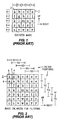
- the digitized image array 1 may be thought of as being twenty-five six-bit (or perhaps eight-bit) values stored in a memory data structure organized as a two dimensional array.
- the actual digitized image would preferably be sixteen by sixteen, or perhaps eighteen by eighteen.
- Figure 1 represents an optical image that has been focused on an array of photo detectors (not shown), digitized and then stored in memory. Further, it might be an image that has just been acquired (a sample image) or it might be one that has been obtained some time ago and is being used as a reference image.
- Figure 2 depicts twenty-five locations (the Cartesian product of five X positions called X 1 through X5 and five Y positions called Y 1 through Y5). Each of these twenty-five locations defines a nine member (three by three) ordered collection that will be an instance of input to the filter.
- the filter operates on the ordered nine members (which are multi-bit numbers) and produces a single numerical output that we will associated with the center of the three by three input.
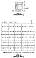
- the filter we shall term the "Standard" filter is shown in Figure 3. It is an array 7 of nine coefficients that is positioned over the enlarged image in each of the twenty-five filter positions indicated by the X(1-5) by Y(1-5) indices. At each of these locations it produces a single output value according to the summations of the cells contributing as multiplied by the coefficients in the filter.
- the array 8 in Figure 4 indicates exactly what five-by-five filtered array will result from application of the Standard filter 7 in Figure 3 to the expanded array 2 of Figure 2.
- Figure 5 where we illustrate a simplified prior art case where the Standard filter behaves in a suitable manner.
- On the left-hand side of Figure 5 are three input images 9, 14 and 19 that a sequence of mouse movements over an unchanging image, as indicated by arrows 24 and 25. The movements are separated by one pixel “down” (image 9 to 14) and then by one pixel “over” (image 14 to 19).
- the images include a distinguishable feature that is a square of four adjacent 1's (shown for convenience only in heavy boxes 10, 15 and 20 in images 9, 14 and 19, respectively).
- These unfiltered input images (9, 14 and 19) include a horizontal grain component, which was added to show that it is filtered out, as it is supposed to be. That horizontal grain component is the top row of 1's in 9, which then becomes next row down from the top in input images 14 and 19.
- the filter is simply an operational combinatorial rule of arithmetic that is applied to a symbol set on the input image. It maps nine adjacent input values into one value in the filtered output. Many different adjacent filter positions are used to create the filtered output image. And while one can compare neighbor symbols in the input or in the output, it is not fair to think that an input symbol (say, a "1") is an indivisible nuclear entity that passes untransformed through the filter and simply comes out the same kind of thing that it was, but just in a different place. We may agree that fundamentally they are all numbers, but what they mean before and after filtering are not the same things.
- the locations in the filtered images 11,16 and 22 of the deformed features varies proportionally (exactly one to one) as the variation of the corresponding input feature in the unfiltered images. It is this well behaved correspondence that allows the correlator to track the deformed image as readily as if it were not deformed.
- the first quadrant (QI) is, of course, the angles zero through ninety degrees, and has a reflection in the third quadrant.
- the second quadrant (QII) is, of course, the range of ninety through one hundred eighty degrees, and has a reflection in the fourth quadrant.
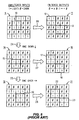
- the filter 52 shown in Figure 7 is called "Filter QI" because it appears to work best on features whose axes lie approximately centered in the first and third quadrants, when the above conventions are followed. So, for example, look at Figure 9 and identify the diagonal grain running from upper left to lower right. Now rotate the figure clockwise about 45 °so that the grain appears to be vertical.
- the filter QI works better on this example than does its companion QII.
- the filter 53 of Figure 8 is called "Filter QII" because it appears to work best on features whose axes lie approximately centered in the second and fourth quadrants.
- Figure 10 is an example similar to that of Figure 6, where we expect the Standard filter to fail, but that the filter QII 53 functions.
- the diagonal grain runs form upper right to lower left, and the feature (four adjacent 1's highlighted in heavy boxes 77, 78 and 79) starts out in a slightly different location and moves along a slightly different path.
- Arrow 86 indicates that it moves down one pixel from image 71 to become image 72
- arrow 87 indicates that image 72 moves over one pixel to the left to become image 73 (previous examples moved to the right).
- the optical navigation system keeps track of its velocity (speed and direction), and uses that information to predict where the next sample frame will probably fall on the reference frame in use. That is to say, where on the (filtered) reference frame should the next (filtered) sample frame be centered prior to correlation.
- Correlation involves the making of nine (or perhaps more, but nine is typical) comparisons between the nine trial sample frame positions and the reference frame, with the idea being that at one of those positions the images will line-up or match better than at any of the others.
- the nine positions are: no change (use the prediction unaltered); one pixel up; one pixel up and one to the left; one up and one to the right; one to the left; one to the right; one down; one down and one to the left; and, one down and one to the right.
- the filter outputs being sign bits only, the comparison process at each trial position for correlation is relatively easy.
- the correlation process "normalizes" the correlation numbers so that they all have the same weight despite the varying degrees of frame boundary mis-registration associated with their individual calculation circumstances. It is these normalized numbers that we use for the correlation surface, and which drive the navigation process.)
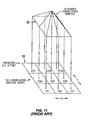
- the tool we shall use to predict the best filter to use analyzes the shape of the correlation surface.
- the tool will detect when the correlation surface 89 develops ridges, instead of having an isolated peak.
- ridges could appear in two ways: aligned with the axes and diagonally. With that in mind, we define the following two metrics:
- the metric AR (for Axial Ridge) indicates presence of a ridge that runs in a direction parallel with one of the axes. If the absolute value of AR gets above a certain threshold (say, 15% or 20% of the maximum value of a cell in the correlation array 88), then we become suspicious of how well the filter in use is performing.
- the "raw" component of AR (the sum of the two differences within the braces) is filtered by an exponential or auto-regression mechanism ( ) to retard its rate of change by a suitable time constant. Furthermore, only images whose separations in the X and Y axes are small enough to imply a good correlation surface are used to calculate AR.
- RM Radge Metric
- RM is a convenient way to unify a common meaning of those two metrics into a single indicator.
- the signs of AR and DR contain useful information. If we assume that in a system of the sort we have been describing that a correlation surface can get ridges (or the bowl --as viewed from below -- can get troughs), then we can also expect that a properly operating system will not experience, after suitable filtering, non-transient troughs in its correlation surface (or ridges in a bowl).
- FIG 12 is a state diagram 90 of how an optical navigation system, such as for a mouse, and using the techniques set out herein, may be made less susceptible to the mischief caused by grain in the surface to be navigated upon.
- a transition START 91 enters a state 92 NAVIGATE WITH STANDARD FILTER. While in this state the optical navigation system operates mostly in a conventional manner and uses the Standard Filter 7, except that it is calculating and monitoring AR, DR and RM.
- the transition 93 from state 92 to itself indicates this for situations where RM has a value that indicates an absence of ridges in the correlation surface 89.
- RM changes to indicate the emergence of a ridge in the correlation surface 89. Since it is the Standard filter 7 that is presently in use. we may assume that it is a diagonal ridge that is appearing, as we know the Standard filter is effective in removing axial ridges. There are two ways that a diagonal ridge can appear, however (upper left to lower right, and upper right to lower left), and the filter QI 52 has, in one embodiment, been found to work best for upper left to lower right, while the filter QII 53 has been found to work best for diagonal grain going from upper right to lower left. The difference between the two cases is indicated by the sign of DR, as explained previously.
- transition 94 leads to the state 95 NAVIGATE WITH FILTER QII.
- Transition 100 keeps state 95 in effect as long as DR ⁇ 0 remains the case. If DR changes sign to DR ⁇ 0, however, transition 98 puts state 92 NAVIGATE WITH STANDARD FILTER back into effect.
- transition 96 leads to the state 97 NAVIGATE WITH FILTER QI.
- Transition 101 keeps state 97 in effect as long as DR ⁇ 0 remains the case. If DR changes sign to DR ⁇ 0, however, transition 99 puts state 92 NAVIGATE WITH STANDARD FILTER back into effect.
- the light source create highlights and shadows on the surface to be navigated upon. This is best done by creating a low or"grazing" angle of incidence for the light from the source of illumination.
- the source of illumination was located at (according to ourangular convention) 180°.
- the Standard filter has different ranges of operation about the X axis 90° than about the Y axis. It appears that the wider range of operation abut the Y axis arises from the visibility ofthe grain being minimized by end-on illumination, compared to the X axis case where the visibility of the grain is maximized by broadside illumination. Coping with the X axis case is left entirely up to the filter, whereas in the Y axis case the manner of illumination assists the filter.
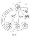
- the state diagram 102 of Figure 13 illustrates how this can be implemented, assuming that the different locations of illumination shown in Figure 14 are available. If there were more cells than nine in the correlation surface, then greater granularity than just two kinds of axial granularity and two kinds of diagonal granularity could be observed, and a more refined response in terms of a selected location for illumination would be possible.
- the filter in use is changed and the location of the source of illumination is altered, as well.
- the surface being navigated upon has a grain that, instead of being actual groves, is a pattern of discrete holes or projections whose highlights and shadows combine to synthesise a grain.
- the discrete nature of the hole or projections would mean that they continue to create highlights and shadows (they remain visible as grain) regardless of the direction of illumination.
- the amount of grain in the image presented to the spatial filter would thus vary only slightly as a function of the direction of illumination.
Landscapes
- Engineering & Computer Science (AREA)
- General Engineering & Computer Science (AREA)
- Theoretical Computer Science (AREA)
- Human Computer Interaction (AREA)
- Physics & Mathematics (AREA)
- General Physics & Mathematics (AREA)
- Image Analysis (AREA)
- Image Processing (AREA)
- Position Input By Displaying (AREA)
Applications Claiming Priority (2)
| Application Number | Priority Date | Filing Date | Title |
|---|---|---|---|
| US845544 | 2001-04-30 | ||
| US09/845,544 US6603111B2 (en) | 2001-04-30 | 2001-04-30 | Image filters and source of illumination for optical navigation upon arbitrary surfaces are selected according to analysis of correlation during navigation |
Publications (2)
| Publication Number | Publication Date |
|---|---|
| EP1255219A1 EP1255219A1 (en) | 2002-11-06 |
| EP1255219B1 true EP1255219B1 (en) | 2003-12-10 |
Family
ID=25295473
Family Applications (1)
| Application Number | Title | Priority Date | Filing Date |
|---|---|---|---|
| EP02252696A Expired - Lifetime EP1255219B1 (en) | 2001-04-30 | 2002-04-16 | Optical navigation system |
Country Status (5)
| Country | Link |
|---|---|
| US (2) | US6603111B2 (https=) |
| EP (1) | EP1255219B1 (https=) |
| JP (1) | JP2002342017A (https=) |
| KR (1) | KR100869441B1 (https=) |
| DE (1) | DE60200122T2 (https=) |
Cited By (2)
| Publication number | Priority date | Publication date | Assignee | Title |
|---|---|---|---|---|
| US7439954B2 (en) | 2004-04-15 | 2008-10-21 | Logitech Europe S.A. | Multi-light-source illumination system for optical pointing devices |
| US7872639B2 (en) | 2005-06-30 | 2011-01-18 | Logitech Europe S.A. | Optical displacement detection over varied surfaces |
Families Citing this family (52)
| Publication number | Priority date | Publication date | Assignee | Title |
|---|---|---|---|---|
| US6823077B2 (en) * | 2001-07-30 | 2004-11-23 | Agilent Technologies, Inc. | Simplified interpolation for an optical navigation system that correlates images of one bit resolution |
| KR100622404B1 (ko) * | 2002-10-23 | 2006-09-13 | 주식회사 애트랩 | 광 이미지 검출기 및 이를 채택하는 광 마우스 |
| US6995748B2 (en) * | 2003-01-07 | 2006-02-07 | Agilent Technologies, Inc. | Apparatus for controlling a screen pointer with a frame rate based on velocity |
| US7423227B2 (en) * | 2003-09-04 | 2008-09-09 | Avago Technologies Ecbu Ip Pte Ltd | Apparatus for optical navigation |
| EP1531386A1 (en) * | 2003-11-11 | 2005-05-18 | STMicroelectronics Limited | Optical pointing device |
| US7613329B2 (en) * | 2004-03-08 | 2009-11-03 | Avago Technologies Ecbu Ip (Singapore) Pte. Ltd. | Apparatus for controlling the position of a screen pointer that detects defective pixels |
| US7474297B2 (en) * | 2004-03-22 | 2009-01-06 | Avago Technologies Ecbu Ip (Singapore) Pte. | Contaminant-resistant optical mouse and cradle |
| US7446756B2 (en) * | 2004-03-22 | 2008-11-04 | Avago Technologies Ecbu Ip (Singapore) Pte. Ltd. | Apparatus for controlling the position of a screen pointer with low sensitivity to particle contamination |
| CN100391283C (zh) * | 2004-04-30 | 2008-05-28 | 华为技术有限公司 | 一种具备摄像功能的移动终端及其控制摄像功能的方法 |
| US7042575B2 (en) * | 2004-05-21 | 2006-05-09 | Silicon Light Machines Corporation | Speckle sizing and sensor dimensions in optical positioning device |
| US20050259097A1 (en) * | 2004-05-21 | 2005-11-24 | Silicon Light Machines Corporation | Optical positioning device using different combinations of interlaced photosensitive elements |
| US7268341B2 (en) | 2004-05-21 | 2007-09-11 | Silicon Light Machines Corporation | Optical position sensing device including interlaced groups of photosensitive elements |
| US7773070B2 (en) * | 2004-05-21 | 2010-08-10 | Cypress Semiconductor Corporation | Optical positioning device using telecentric imaging |
| US20050258346A1 (en) * | 2004-05-21 | 2005-11-24 | Silicon Light Machines Corporation | Optical positioning device resistant to speckle fading |
| US7285766B2 (en) * | 2004-05-21 | 2007-10-23 | Silicon Light Machines Corporation | Optical positioning device having shaped illumination |
| US20050259078A1 (en) * | 2004-05-21 | 2005-11-24 | Silicon Light Machines Corporation | Optical positioning device with multi-row detector array |
| US7315013B2 (en) * | 2004-06-17 | 2008-01-01 | Avago Technologies Ecbu Ip (Singapore) Pte Ltd. | Optical navigation using one-dimensional correlation |
| US7565034B2 (en) * | 2004-06-17 | 2009-07-21 | Avago Technologies Ecbu Ip (Singapore) Pte. Ltd. | Determination of a navigation window in an optical navigation system |
| EP1615045A1 (en) * | 2004-07-07 | 2006-01-11 | STMicroelectronics Limited | Optical detection of relative motion |
| US20060023970A1 (en) * | 2004-07-29 | 2006-02-02 | Chinlee Wang | Optical tracking sensor method |
| US7138620B2 (en) * | 2004-10-29 | 2006-11-21 | Silicon Light Machines Corporation | Two-dimensional motion sensor |
| US7248345B2 (en) * | 2004-11-12 | 2007-07-24 | Silicon Light Machines Corporation | Signal processing method for use with an optical navigation system |
| US7405389B2 (en) * | 2004-11-19 | 2008-07-29 | Silicon Light Machines Corporation | Dense multi-axis array for motion sensing |
| TW200627252A (en) * | 2004-12-02 | 2006-08-01 | Silicon Light Machines Corp | Signal processing method for optical sensors |
| KR100642499B1 (ko) * | 2005-12-02 | 2006-11-10 | 주식회사 애트랩 | 광 네비게이션 장치 및 이의 동작 방법 |
| US7567235B2 (en) | 2005-12-12 | 2009-07-28 | Cypress Semiconductor Corporation | Self-aligning optical sensor package |
| US7765251B2 (en) * | 2005-12-16 | 2010-07-27 | Cypress Semiconductor Corporation | Signal averaging circuit and method for sample averaging |
| US8471191B2 (en) | 2005-12-16 | 2013-06-25 | Cypress Semiconductor Corporation | Optical navigation system having a filter-window to seal an enclosure thereof |
| US7737948B2 (en) * | 2005-12-20 | 2010-06-15 | Cypress Semiconductor Corporation | Speckle navigation system |
| US7298460B2 (en) * | 2006-01-03 | 2007-11-20 | Silicon Light Machines Corporation | Method for determining motion using a velocity predictor |
| US7884801B1 (en) | 2006-02-16 | 2011-02-08 | Cypress Semiconductor Corporation | Circuit and method for determining motion with redundant comb-arrays |
| US7593833B2 (en) * | 2006-03-03 | 2009-09-22 | At&T Intellectual Property I, L.P. | System and method for determining performance of network lines |
| US7297912B1 (en) | 2006-03-27 | 2007-11-20 | Silicon Light Machines Corporation | Circuit and method for reducing power consumption in an optical navigation system having redundant arrays |
| US7809035B2 (en) * | 2006-03-31 | 2010-10-05 | Cypress Semiconductor Corporation | Eye-safe laser navigation sensor |
| US7721609B2 (en) | 2006-03-31 | 2010-05-25 | Cypress Semiconductor Corporation | Method and apparatus for sensing the force with which a button is pressed |
| US7492445B1 (en) | 2006-06-05 | 2009-02-17 | Cypress Semiconductor Corporation | Method and apparatus for robust velocity prediction |
| US7755604B2 (en) | 2006-06-19 | 2010-07-13 | Cypress Semiconductor Corporation | Optical navigation sensor with tracking and lift detection for optically transparent contact surfaces |
| US7728816B2 (en) * | 2006-07-10 | 2010-06-01 | Cypress Semiconductor Corporation | Optical navigation sensor with variable tracking resolution |
| US7742514B1 (en) | 2006-10-31 | 2010-06-22 | Cypress Semiconductor Corporation | Laser navigation sensor |
| US8072429B2 (en) * | 2006-12-22 | 2011-12-06 | Cypress Semiconductor Corporation | Multi-axial touch-sensor device with multi-touch resolution |
| US8314774B1 (en) | 2007-07-09 | 2012-11-20 | Cypress Semiconductor Corporation | Method and apparatus for quasi-3D tracking using 2D optical motion sensors |
| US8263921B2 (en) | 2007-08-06 | 2012-09-11 | Cypress Semiconductor Corporation | Processing methods for speckle-based motion sensing |
| US20090135140A1 (en) * | 2007-11-27 | 2009-05-28 | Logitech Europe S.A. | System and method for accurate lift-detection of an input device |
| US8259069B1 (en) | 2008-01-11 | 2012-09-04 | Cypress Semiconductor Corporation | Speckle-based optical navigation on curved tracking surface |
| US8031176B1 (en) | 2008-01-22 | 2011-10-04 | Cypress Semiconductor Corporation | Optical navigation system using a single-package motion sensor |
| US8541727B1 (en) | 2008-09-30 | 2013-09-24 | Cypress Semiconductor Corporation | Signal monitoring and control system for an optical navigation sensor |
| US7723659B1 (en) | 2008-10-10 | 2010-05-25 | Cypress Semiconductor Corporation | System and method for screening semiconductor lasers |
| US8217334B1 (en) | 2008-12-24 | 2012-07-10 | Cypress Semiconductor Corporation | Optical navigation sensor including a spatial frequency filter |
| US8711096B1 (en) | 2009-03-27 | 2014-04-29 | Cypress Semiconductor Corporation | Dual protocol input device |
| US8576402B2 (en) | 2010-07-22 | 2013-11-05 | Avago Technologies General Ip (Singapore) Pte. Ltd. | Optical navigation with specular reflection blocking |
| CN102959494B (zh) | 2011-06-16 | 2017-05-17 | 赛普拉斯半导体公司 | 具有电容式传感器的光学导航模块 |
| US8896553B1 (en) | 2011-11-30 | 2014-11-25 | Cypress Semiconductor Corporation | Hybrid sensor module |
Family Cites Families (8)
| Publication number | Priority date | Publication date | Assignee | Title |
|---|---|---|---|---|
| US7171016B1 (en) * | 1993-11-18 | 2007-01-30 | Digimarc Corporation | Method for monitoring internet dissemination of image, video and/or audio files |
| JPH096523A (ja) * | 1995-06-20 | 1997-01-10 | Nec Eng Ltd | 光学式入力装置 |
| US6408331B1 (en) * | 1995-07-27 | 2002-06-18 | Digimarc Corporation | Computer linking methods using encoded graphics |
| US5786804A (en) * | 1995-10-06 | 1998-07-28 | Hewlett-Packard Company | Method and system for tracking attitude |
| TW472206B (en) * | 1998-03-30 | 2002-01-11 | Agilent Technologies Inc | Seeing eye mouse for a computer system |
| US6057540A (en) * | 1998-04-30 | 2000-05-02 | Hewlett-Packard Co | Mouseless optical and position translation type screen pointer control for a computer system |
| US5994710A (en) | 1998-04-30 | 1999-11-30 | Hewlett-Packard Company | Scanning mouse for a computer system |
| US6738097B2 (en) * | 2001-04-11 | 2004-05-18 | Oki Electric Industry Co, Ltd. | Composite video signal decoder having stripe component judging section |
-
2001
- 2001-04-30 US US09/845,544 patent/US6603111B2/en not_active Expired - Lifetime
-
2002
- 2002-04-16 DE DE60200122T patent/DE60200122T2/de not_active Expired - Fee Related
- 2002-04-16 EP EP02252696A patent/EP1255219B1/en not_active Expired - Lifetime
- 2002-04-23 JP JP2002120990A patent/JP2002342017A/ja not_active Withdrawn
- 2002-04-29 KR KR1020020023462A patent/KR100869441B1/ko not_active Expired - Lifetime
-
2003
- 2003-06-03 US US10/453,391 patent/US6737636B2/en not_active Expired - Fee Related
Cited By (2)
| Publication number | Priority date | Publication date | Assignee | Title |
|---|---|---|---|---|
| US7439954B2 (en) | 2004-04-15 | 2008-10-21 | Logitech Europe S.A. | Multi-light-source illumination system for optical pointing devices |
| US7872639B2 (en) | 2005-06-30 | 2011-01-18 | Logitech Europe S.A. | Optical displacement detection over varied surfaces |
Also Published As
| Publication number | Publication date |
|---|---|
| US6737636B2 (en) | 2004-05-18 |
| EP1255219A1 (en) | 2002-11-06 |
| US20030205666A1 (en) | 2003-11-06 |
| US20020179823A1 (en) | 2002-12-05 |
| JP2002342017A (ja) | 2002-11-29 |
| KR20020084414A (ko) | 2002-11-07 |
| KR100869441B1 (ko) | 2008-11-21 |
| DE60200122D1 (de) | 2004-01-22 |
| US6603111B2 (en) | 2003-08-05 |
| DE60200122T2 (de) | 2004-07-08 |
Similar Documents
| Publication | Publication Date | Title |
|---|---|---|
| EP1255219B1 (en) | Optical navigation system | |
| US6657184B2 (en) | Optical navigation upon grainy surfaces using multiple navigation sensors | |
| Brajovic et al. | Computational sensor for visual tracking with attention | |
| EP1524590A2 (en) | Tracking motion using an interference pattern | |
| US20030103037A1 (en) | Sensing device for optical pointing devices such as an optical mouse | |
| WO2016192534A1 (en) | Optical device for detecting an internal flaw of a transparent substrate and method for the same | |
| CN111274834A (zh) | 光学代码的读取 | |
| EP0504633B1 (en) | Minimum difference processor | |
| US7639236B2 (en) | Image sensor, optical pointing device and motion calculating method of optical pointing device | |
| US11397493B2 (en) | Method for touch sensing enhancement implemented in single chip, single chip capable of achieving touch sensing enhancement, and computing apparatus | |
| US7315013B2 (en) | Optical navigation using one-dimensional correlation | |
| US20070154069A1 (en) | Displacement estimation device and method for the same | |
| JP2693586B2 (ja) | 画像識別・追尾装置 | |
| JPH0531791B2 (https=) | ||
| JP2003150898A (ja) | 画像内パターン位置検出方法、装置、プログラムおよびプログラムが記録された記録媒体 | |
| Davis et al. | RSTA on the Move: Detection and Tracking of Moving Objects from an Autonomous Mobile Platform. | |
| US7382935B2 (en) | Homogeneous and plain surface detection in optical navigation systems | |
| JP7842749B2 (ja) | 情報処理システム及び情報処理方法 | |
| US20260065634A1 (en) | Image processing apparatus, image processing method, and non-transitory computer-readable storage medium | |
| JP2001154795A (ja) | 入力装置及び入力プログラムを記録した記録媒体 | |
| JP2008145121A (ja) | 三次元形状測定装置 | |
| Perov et al. | Privacy-Preserving Localization and Social Distance Monitoring with Low-Resolution Thermal Imaging and Deep Learning | |
| Liu et al. | Research on a Motion-Awareness Guided Semantic Dynamic SLAM Algorithm | |
| JPH07128013A (ja) | 光学式位置検出装置 | |
| SU1737471A1 (ru) | Устройство дл выделени контура изображени |
Legal Events
| Date | Code | Title | Description |
|---|---|---|---|
| PUAI | Public reference made under article 153(3) epc to a published international application that has entered the european phase |
Free format text: ORIGINAL CODE: 0009012 |
|
| AK | Designated contracting states |
Kind code of ref document: A1 Designated state(s): AT BE CH CY DE DK ES FI FR GB GR IE IT LI LU MC NL PT SE TR |
|
| AX | Request for extension of the european patent |
Free format text: AL;LT;LV;MK;RO;SI |
|
| 17P | Request for examination filed |
Effective date: 20021021 |
|
| GRAH | Despatch of communication of intention to grant a patent |
Free format text: ORIGINAL CODE: EPIDOS IGRA |
|
| RIC1 | Information provided on ipc code assigned before grant |
Ipc: 7G 06F 3/033 B Ipc: 7G 06K 11/20 B Ipc: 7G 06K 11/18 B Ipc: 7G 06K 11/08 A |
|
| RIC1 | Information provided on ipc code assigned before grant |
Ipc: 7G 06F 3/033 B Ipc: 7G 06K 11/20 B Ipc: 7G 06K 11/18 B Ipc: 7G 06K 11/08 A |
|
| RIC1 | Information provided on ipc code assigned before grant |
Ipc: 7G 06F 3/033 B Ipc: 7G 06K 11/20 B Ipc: 7G 06K 11/18 B Ipc: 7G 06K 11/08 A |
|
| AKX | Designation fees paid |
Designated state(s): DE FR GB |
|
| GRAS | Grant fee paid |
Free format text: ORIGINAL CODE: EPIDOSNIGR3 |
|
| GRAA | (expected) grant |
Free format text: ORIGINAL CODE: 0009210 |
|
| AK | Designated contracting states |
Kind code of ref document: B1 Designated state(s): DE FR GB |
|
| REG | Reference to a national code |
Ref country code: GB Ref legal event code: FG4D |
|
| REG | Reference to a national code |
Ref country code: IE Ref legal event code: FG4D |
|
| REF | Corresponds to: |
Ref document number: 60200122 Country of ref document: DE Date of ref document: 20040122 Kind code of ref document: P |
|
| ET | Fr: translation filed | ||
| PLBE | No opposition filed within time limit |
Free format text: ORIGINAL CODE: 0009261 |
|
| STAA | Information on the status of an ep patent application or granted ep patent |
Free format text: STATUS: NO OPPOSITION FILED WITHIN TIME LIMIT |
|
| 26N | No opposition filed |
Effective date: 20040913 |
|
| REG | Reference to a national code |
Ref country code: IE Ref legal event code: MM4A |
|
| PGFP | Annual fee paid to national office [announced via postgrant information from national office to epo] |
Ref country code: FR Payment date: 20060417 Year of fee payment: 5 |
|
| PGFP | Annual fee paid to national office [announced via postgrant information from national office to epo] |
Ref country code: GB Payment date: 20060424 Year of fee payment: 5 |
|
| PGFP | Annual fee paid to national office [announced via postgrant information from national office to epo] |
Ref country code: DE Payment date: 20060531 Year of fee payment: 5 |
|
| REG | Reference to a national code |
Ref country code: GB Ref legal event code: 732E |
|
| GBPC | Gb: european patent ceased through non-payment of renewal fee |
Effective date: 20070416 |
|
| PG25 | Lapsed in a contracting state [announced via postgrant information from national office to epo] |
Ref country code: DE Free format text: LAPSE BECAUSE OF NON-PAYMENT OF DUE FEES Effective date: 20071101 |
|
| PG25 | Lapsed in a contracting state [announced via postgrant information from national office to epo] |
Ref country code: GB Free format text: LAPSE BECAUSE OF NON-PAYMENT OF DUE FEES Effective date: 20070416 |
|
| PG25 | Lapsed in a contracting state [announced via postgrant information from national office to epo] |
Ref country code: FR Free format text: LAPSE BECAUSE OF NON-PAYMENT OF DUE FEES Effective date: 20070430 |