EP1254599A2 - Water-sealing component assembly - Google Patents
Water-sealing component assembly Download PDFInfo
- Publication number
- EP1254599A2 EP1254599A2 EP02251592A EP02251592A EP1254599A2 EP 1254599 A2 EP1254599 A2 EP 1254599A2 EP 02251592 A EP02251592 A EP 02251592A EP 02251592 A EP02251592 A EP 02251592A EP 1254599 A2 EP1254599 A2 EP 1254599A2
- Authority
- EP
- European Patent Office
- Prior art keywords
- water
- component
- bearing
- attached
- component assembly
- Prior art date
- Legal status (The legal status is an assumption and is not a legal conclusion. Google has not performed a legal analysis and makes no representation as to the accuracy of the status listed.)
- Granted
Links
- 238000007789 sealing Methods 0.000 title claims abstract description 21
- 238000009987 spinning Methods 0.000 claims description 16
- 229920005989 resin Polymers 0.000 claims description 6
- 239000011347 resin Substances 0.000 claims description 6
- 230000001419 dependent effect Effects 0.000 claims 3
- 241000251468 Actinopterygii Species 0.000 claims 1
- XLYOFNOQVPJJNP-UHFFFAOYSA-N water Substances O XLYOFNOQVPJJNP-UHFFFAOYSA-N 0.000 abstract description 21
- 230000009545 invasion Effects 0.000 abstract description 7
- 229920001343 polytetrafluoroethylene Polymers 0.000 description 5
- 239000004810 polytetrafluoroethylene Substances 0.000 description 5
- 230000000712 assembly Effects 0.000 description 4
- 238000000429 assembly Methods 0.000 description 4
- 230000002093 peripheral effect Effects 0.000 description 4
- 230000009977 dual effect Effects 0.000 description 3
- 238000007747 plating Methods 0.000 description 3
- -1 polytetrafluoroethylene Polymers 0.000 description 2
- 239000005871 repellent Substances 0.000 description 2
- 229920002050 silicone resin Polymers 0.000 description 2
- 229910000838 Al alloy Inorganic materials 0.000 description 1
- 238000005266 casting Methods 0.000 description 1
- 239000003795 chemical substances by application Substances 0.000 description 1
- 239000000470 constituent Substances 0.000 description 1
- 230000007423 decrease Effects 0.000 description 1
- 238000007599 discharging Methods 0.000 description 1
- 230000000694 effects Effects 0.000 description 1
- 230000004048 modification Effects 0.000 description 1
- 238000012986 modification Methods 0.000 description 1
- 239000004033 plastic Substances 0.000 description 1
- 230000002459 sustained effect Effects 0.000 description 1
- 238000004804 winding Methods 0.000 description 1
Images



Classifications
-
- A—HUMAN NECESSITIES
- A01—AGRICULTURE; FORESTRY; ANIMAL HUSBANDRY; HUNTING; TRAPPING; FISHING
- A01K—ANIMAL HUSBANDRY; AVICULTURE; APICULTURE; PISCICULTURE; FISHING; REARING OR BREEDING ANIMALS, NOT OTHERWISE PROVIDED FOR; NEW BREEDS OF ANIMALS
- A01K89/00—Reels
-
- A—HUMAN NECESSITIES
- A01—AGRICULTURE; FORESTRY; ANIMAL HUSBANDRY; HUNTING; TRAPPING; FISHING
- A01K—ANIMAL HUSBANDRY; AVICULTURE; APICULTURE; PISCICULTURE; FISHING; REARING OR BREEDING ANIMALS, NOT OTHERWISE PROVIDED FOR; NEW BREEDS OF ANIMALS
- A01K89/00—Reels
- A01K89/01—Reels with pick-up, i.e. with the guiding member rotating and the spool not rotating during normal retrieval of the line
-
- A—HUMAN NECESSITIES
- A01—AGRICULTURE; FORESTRY; ANIMAL HUSBANDRY; HUNTING; TRAPPING; FISHING
- A01K—ANIMAL HUSBANDRY; AVICULTURE; APICULTURE; PISCICULTURE; FISHING; REARING OR BREEDING ANIMALS, NOT OTHERWISE PROVIDED FOR; NEW BREEDS OF ANIMALS
- A01K89/00—Reels
- A01K89/01—Reels with pick-up, i.e. with the guiding member rotating and the spool not rotating during normal retrieval of the line
- A01K89/01121—Frame details
- A01K89/011221—Frame details with line or water shields
-
- A—HUMAN NECESSITIES
- A01—AGRICULTURE; FORESTRY; ANIMAL HUSBANDRY; HUNTING; TRAPPING; FISHING
- A01K—ANIMAL HUSBANDRY; AVICULTURE; APICULTURE; PISCICULTURE; FISHING; REARING OR BREEDING ANIMALS, NOT OTHERWISE PROVIDED FOR; NEW BREEDS OF ANIMALS
- A01K89/00—Reels
- A01K89/01—Reels with pick-up, i.e. with the guiding member rotating and the spool not rotating during normal retrieval of the line
- A01K89/01121—Frame details
- A01K89/011223—Frame details with bearing features
-
- F—MECHANICAL ENGINEERING; LIGHTING; HEATING; WEAPONS; BLASTING
- F16—ENGINEERING ELEMENTS AND UNITS; GENERAL MEASURES FOR PRODUCING AND MAINTAINING EFFECTIVE FUNCTIONING OF MACHINES OR INSTALLATIONS; THERMAL INSULATION IN GENERAL
- F16C—SHAFTS; FLEXIBLE SHAFTS; ELEMENTS OR CRANKSHAFT MECHANISMS; ROTARY BODIES OTHER THAN GEARING ELEMENTS; BEARINGS
- F16C33/00—Parts of bearings; Special methods for making bearings or parts thereof
- F16C33/72—Sealings
- F16C33/76—Sealings of ball or roller bearings
- F16C33/78—Sealings of ball or roller bearings with a diaphragm, disc, or ring, with or without resilient members
- F16C33/784—Sealings of ball or roller bearings with a diaphragm, disc, or ring, with or without resilient members mounted to a groove in the inner surface of the outer race and extending toward the inner race
- F16C33/7843—Sealings of ball or roller bearings with a diaphragm, disc, or ring, with or without resilient members mounted to a groove in the inner surface of the outer race and extending toward the inner race with a single annular sealing disc
- F16C33/7846—Sealings of ball or roller bearings with a diaphragm, disc, or ring, with or without resilient members mounted to a groove in the inner surface of the outer race and extending toward the inner race with a single annular sealing disc with a gap between the annular disc and the inner race
- F16C33/785—Bearing shields made of sheet metal
-
- F—MECHANICAL ENGINEERING; LIGHTING; HEATING; WEAPONS; BLASTING
- F16—ENGINEERING ELEMENTS AND UNITS; GENERAL MEASURES FOR PRODUCING AND MAINTAINING EFFECTIVE FUNCTIONING OF MACHINES OR INSTALLATIONS; THERMAL INSULATION IN GENERAL
- F16C—SHAFTS; FLEXIBLE SHAFTS; ELEMENTS OR CRANKSHAFT MECHANISMS; ROTARY BODIES OTHER THAN GEARING ELEMENTS; BEARINGS
- F16C2202/00—Solid materials defined by their properties
- F16C2202/66—Water repelling
Definitions
- the present invention relates to water-sealing component assemblies, in particular to water-sealing component assemblies composed of a relatively rotatable plurality of components.
- Rotatory components such as rod members and gears to which bearings are fitted may be cited as examples in component assemblies that are made up of a relatively rotatable plurality of components. Such rotatory components are used as constituent parts in, for example, fishing reels and bicycles.
- fishing reels that reel fishing line while being mounted onto a fishing rod, there are chiefly spinning reels, dual-bearing reels and cantilevered-bearing reels.
- a fishing reel of these types includes a reel unit that mounts onto a fishing rod, and a spool that is fitted to the reel unit and is for winding on fishing line through rotation of the handle.
- the spool In dual-bearing reels and cantilevered-bearing reels, the spool is rotatably supported in the reel unit via bearings. In spinning reels, the spool is mounted axially movably as well as rotatably with respect to the reel unit.
- the sealing member is, for example, an element made of plastic, and is arranged in between rotatory components or stationary components, and mounted for contacting on a rotatory component.
- Fitting sealing members in the clearances between the rotatory components enables the foregoing conventional fishing-reel component assemblies to prevent water droplets from invading the rotatory-component clearances. Nevertheless, since the sealing members are disposed contacting a rotatory component, frictional force acting on the rotatory component due to the sealing-member contact is liable to impair the rotational efficiency of the rotatory component.
- An object of the present invention is to prevent invasion of water droplets into rotatory-component clearances in a component assembly composed of a relatively rotatable plurality of components, while sustaining rotational efficiency of the rotatory components.
- a component assembly in accordance with the first aspect of the invention is a component assembly composed from a relatively rotatable plurality of components and superficially subjected to a water-repellency treatment, the component assembly furnished with: a first component; a second component arranged relatively rotatably leaving a clearance with respect to the first component; and a water-repelling film layer built over at least any one surface of the first component and the second component that forms the clearance.
- a water-repellent film layer is built on the surfaces that form the clearance between the rotating first component and second component in this component assembly.
- a water-repelling film layer such as silicone resin or fluorinated resin for example, having water-repellent properties is formed, without a member in addition to the sealing element being installed. Accordingly, invasion of water droplets into the clearance between the first component and the second component is prevented while sustaining rotational efficiency of the first and second components.
- a component assembly in accordance with the second aspect of the invention is the component assembly set forth by the first aspect, further including a ground-layer film in between at least either one of the first and second components, and the water-repelling film layer.
- the adhesiveness of the water-repelling layer may be improved by for example implementing as a ground-layer film a foundation treatment of various kinds.
- a component assembly in accordance with the third aspect of the invention is the component assembly set forth by the first or second aspect, wherein the water-repelling film layer is a thin metallic film impregnated with a fluorinated resin.
- Water-repelling efficacy may be heightened herein by impregnating for example an electroless nickel-plating layer that is the thin metallic film with a fluorinated resin such as polytetrafluoroethylene (PTFE).
- PTFE polytetrafluoroethylene
- a component assembly in accordance with the fourth aspect of the invention is the component assembly set forth by any of first through third aspects, wherein the water-repelling film layer is formed on at least a one surface among mutually opposing surfaces of the first component and the second component.
- invasion of water droplets into the clearance in between the first component and the second component may be prevented by forming the water-repelling film layer on an opposing surface of the first and second components.
- a component assembly in accordance with the fifth aspect of the invention is the component assembly set forth by any of first through fourth aspects, wherein the water-repelling film layer is formed on a surface contiguous with at least a one surface among mutually opposing surfaces of the first component and the second component. Water droplets invading the clearance in between the first component and the second component may be prevented in this case by forming the water-repelling film layer for example on the peripheral rim of an opening along which the first and second components are exteriorly exposed.
- a component assembly in accordance with the sixth aspect of the invention is the component assembly set forth by any of first through fifth aspects, wherein one of the first component and the second component is a pressing member attached to the outer race of a bearing, and the other of the first component and the second component is a rod member attached to the inner race of the bearing. Water droplets invading the clearance in between a pressing member and a rod member in this case may be prevented by forming the water-repelling film layer on the pressing member and the rod member.
- the pressing member is for example a retainer that, attached to the front of the rotatory frame of the rotor, presses on the outer race
- the rod member is the spool shaft.
- a drainage hole for discharging water droplets under centrifugal force during rotation further may be formed in the retainer.
- the drainage hole does not require being subjected superficially to a water-repellency treatment, or else may be subjected superficially to a hydrophilic treatment having hydrophilic power under centrifugal force.
- a component assembly in accordance with the seventh aspect of the invention is the component assembly set forth by any of first through sixth aspects, wherein one of the first component and the second component is a pressing member attached to the outer race of a bearing, and the other of the first component and the second component is a cylindrical member fitted on a rod member attached to the inner race of the bearing.
- Water droplets invading the clearance in between a pressing member and a cylindrical member in this case may be prevented by forming the water-repelling film layer on the pressing member and the cylindrical member.
- the pressing member is for example an element that presses on the outer race
- the cylindrical member is an element that presses on the inner race
- the rod member is a pinion gear.
- the water-repelling efficacy may be further improved by forming the contour of the cylindrical member in a shape off which water droplets readily bounce, such as a taper shape, a fin shape, or an involute shape.
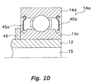
- a component assembly in accordance with the eighth aspect of the invention is the component assembly set forth by any of first through seventh aspects, wherein one of the first component and the second component is a pressing member attached to the inner race of a bearing, and the other of the first component and the second component is a plate-shaped member attached to the outer race of the bearing.
- one of the first component and the second component is a pressing member attached to the inner race of a bearing
- the other of the first component and the second component is a plate-shaped member attached to the outer race of the bearing.
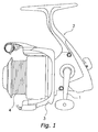
- a spinning reel in which one embodiment of the present invention is adopted is furnished with, as shown in Fig. 1: a handle 1; a reel unit 2 to which the handle 1 is fitted to be rotatable around a left/right shaft; a rotor 3; and a spool 4.
- the rotor 3 rotates in cooperation with rotation of the handle 1 to guide fishing line onto the spool 4, and is rotatable around a front-to-rear shaft supported on the front of the reel unit 2.
- the spool 4 winds fishing line guided by the rotor 3 onto its outer circumferential surface, and is disposed on the front of the rotor 3 movably in the font-rear axial direction.
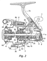
- the reel unit 2 as shown in Fig. 2, includes a reel body 2a composing the chief part of the reel unit 2 and a T-shaped rod-mounting leg 2b extending diagonally up/frontward from and formed integrally with the reel body 2a.
- a rotor-drive mechanism 5 that rotates the rotor 3 by linkage to rotation of the handle 1; and an oscillating mechanism 6 that pumps the spool 4 back and forth to wind fishing line onto the spool 4 uniformly.
- a one-way clutch 51 of an anti-reverse mechanism 50 for prohibiting/releasing rotation (reversal) of the rotor 3 in the line reel-out direction is non-rotatably mounted on the front of the reel body 2a.
- the rotor 3 includes, as shown in Figs. 2 and 3: a round cylinder portion 30 fastened to a later-described pinion gear 12; a first rotor arm 31 and a second rotor arm 32 opposing each other and furnished sideways on the round cylinder portion 30; and a bail arm 40 for guiding fishing line onto the spool 4.
- the round cylinder portion 30 and the first rotor arm 31 and the second rotor arm 32 are made of, e.g., aluminum-alloy, and are formed unitarily.
- a front wall 41 is formed on the front of the round cylinder portion 30.
- a rearward-projecting boss 42 is formed in the center portion of the front wall 41.
- a through-hole into which the pinion gear 12 is non-rotatably interlocked is formed in the center of the boss 42.
- the pinion gear 12 and a spool shaft 15 pass through the through-hole.
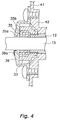
- a nut 33 as shown in Figs. 3 and 4 screws together with the front portion of the pinion gear 12, and thus the rotor 3 is fastened non-rotatably to the fore end of the pinion gear 12 by the nut 33.
- a bearing 35 is disposed along the inner periphery of the nut 33. The bearing 35 is furnished to secure a clearance between the spool shaft 15, to which its inner race 35a is attached, and the inner surface of the nut 33, to which the outer race 35b of the bearing 35 is attached.
- a pressing member 36 (an example of a first component) is mounted on the front faces of the nut 33 and the bearing 35, such that the pressing member 36 abuts on the outer race 35b.
- the pressing member 36 is installed so as to be rotatable with respect to the spool shaft 15 (an example of a second component), which is a rod member.
- the pressing member 36 is formed in a taper shape that tapers frontward, where its peripheral rim portion is fixed by being screwed fast to the boss 42.
- the pressing member 36 as such is water-repellency treated over all its surfaces, including the face that forms a clearance with spool shaft 15.
- the pressing member 36 includes, as shown in Fig. 5, an aluminum-alloy-fabricated body portion 17, and a water-repelling film layer 18 built on the surface of the body portion 17.
- the water-repelling film layer 18 is formed by impregnating an electroless nickel-plating layer that is a thin metallic film with a fluorinated resin such as polytetrafluoroethylene (PTFE).
- PTFE polytetrafluoroethylene
- the spool 4 has, as shown in Fig. 2, a shallow-channel contour, and is disposed between the first rotor arm 31 and the second rotor arm 32 of the rotor 3.
- the spool 4 is linked to the fore end of the spool shaft 15 via a drag mechanism 60.
- the spool 4 includes: a bobbin trunk 4a outer-circumferentially onto which fishing line is wound; a skirt 4b that is integrally formed on the rear of the bobbin trunk 4a; and a front flange 4c established on the front end of the bobbin trunk 4a.
- the bobbin trunk 4a is, as shown in Fig. 3, roughly a two-tiered round cylindrical member having a boss in the center; and the outer circumferential surface of the cylindrical section on the outer peripheral side consists of a peripheral surface paralleling the spool shaft 15.
- the bobbin trunk 4a is fitted, as shown in Fig. 3, rotatively to the spool shaft 15 on two bearings 56, 57 fitted into the boss.
- the skirt 4b a round cylindrical member having a base, flares diametrically from the rear-end portion of the bobbin trunk 4a, then extends rearward.
- the rotor drive mechanism 5 includes a face gear 11 into which the handle 1 is non-rotatably fitted, and a pinion gear 12 that meshes with the face gear 11.
- the face gear 11 is formed unitarily with a face gear spool 11a fitted non-rotatably to a handle shaft 10, and either end of the face gear 11a is rotatively supported via bearings in the reel unit 2.
- the pinion gear 12 a cylindrical component, as shown in Fig. 2 is disposed running in the front-to-rear direction, and is fitted rotatively in the reel body 2a.
- the front portion 12a of the pinion gear 12 passes through the center part of the rotor 3, and in the center part is fastened to the rotor 3 by the nut 33.
- the pinion gear 12 is rotatively supported at the mid-portion and rear end in the axial direction via respective bearings 14a, 14b in the reel body 2a.
- the spool shaft 15 passes through the interior of the pinion gear 12. Along with meshing with the face gear 11, the pinion gear 12 also meshes with the oscillating mechanism 6.
- the oscillating mechanism 6, as shown in Figs. 2, has a worm 21 disposed approximately directly beneath and parallel to the spool shaft 15, a slider 22 that moves back and forth along the worm 21, and an intermediate gear 23 fixed to the fore end of the worm 21.
- the slider 22 is supported so as to be shiftable on two upper/lower guide rods 24 disposed parallel with the worm 21.
- the hind end of the spool shaft 15 is non-rotatably fixed to the slider 22.
- the intermediate gear 23 meshes with the pinion gear 12 via a (not illustrated) gear-down train.
- the anti-reverse mechanism 50 includes, as shown in Fig. 2, the one-way clutch 51, and a switching mechanism 52 that switches the one-way clutch 51 between an actuated state (reverse-prohibited state) and a non-actuated state (reverse-permitted state).
- the switching mechanism 52 includes, as shown in Fig. 2, a stopper shaft 53 that has an operating knob on the end in the rear of the reel body 2a.
- the stopper shaft 53 is mounted on the reel body 2a to be pivotable in between a non-operational posture and an operational posture.
- the other end of the stopper shaft 53 is engaged with the one-way clutch 51, wherein the configuration is such that the pivoting of the stopper shaft 53 switches the one-way clutch 51 between the non-operational posture and the operational posture.
- the drag mechanism 60 mounted, as shown in Figs. 2 and 3, between the spool 4 and the spool shaft 15, is a device for applying drag force to the spool 4.
- the drag mechanism 60 has, as shown in Fig. 3: a knob unit 61 for adjusting the drag force by hand; and a friction unit 62 made up of a plurality of disks that are pressed toward the spool 4 by means of the knob unit 61.
- the bail arm 40 is returned into its line-retrieving posture. This automatically takes place by the functioning of a not-illustrated bail-flipping mechanism while the handle 1 is rotated in the line-retrieving direction.
- the handle 1 torque is transmitted to the pinion gear 12 via the face gear shaft 11a and the face gear 11.
- the torque transmitted to the pinion gear 12 is transmitted from its front portion 12a to the rotor 3, and meanwhile is transmitted via the gear-down train to the oscillating mechanism 6 by the intermediate gear 23 that meshes with the pinion gear 12. Consequently, along with the rotor 3 rotating in the line-retrieving direction, the spool 4 pumps back and forth.
- a water-repelling film layer is provided on the surfaces that form the clearance between the first component and second component, it is possible to prevent invasion of water droplets into the clearance between the relatively rotatable components, while sustaining the rotational efficiency of the rotatory components.
Landscapes
- Life Sciences & Earth Sciences (AREA)
- Environmental Sciences (AREA)
- Animal Husbandry (AREA)
- Biodiversity & Conservation Biology (AREA)
- Engineering & Computer Science (AREA)
- General Engineering & Computer Science (AREA)
- Mechanical Engineering (AREA)
- Sealing Using Fluids, Sealing Without Contact, And Removal Of Oil (AREA)
- Sealing Of Bearings (AREA)
- Crystals, And After-Treatments Of Crystals (AREA)
- Piezo-Electric Or Mechanical Vibrators, Or Delay Or Filter Circuits (AREA)
- Sealing Battery Cases Or Jackets (AREA)
Abstract
Description
As fishing reels that reel fishing line while being mounted onto a fishing rod, there are chiefly spinning reels, dual-bearing reels and cantilevered-bearing reels. A fishing reel of these types includes a reel unit that mounts onto a fishing rod, and a spool that is fitted to the reel unit and is for winding on fishing line through rotation of the handle. In dual-bearing reels and cantilevered-bearing reels, the spool is rotatably supported in the reel unit via bearings. In spinning reels, the spool is mounted axially movably as well as rotatably with respect to the reel unit.
But the present invention is not thereby limited; the water-repelling
Claims (16)
- A water-sealing component assembly, comprising a first component; a second component arranged adjacent said first component such that a clearance is defined between clearance-defining surfaces of said first and second components, said first component being rotatable relative to said second component; and a water-repelling film layer (18) provided on at least one of said clearance-defining surfaces of said first and said second components that define said clearance.
- A water-sealing component assembly as claimed in Claim 1, further comprising a ground-layer film (19) provided in between said water-repelling film (18) and said surface of one of said first and second components on which said water-repelling film layer (18) is provided.
- A water-sealing component assembly as claimed in claimed in Claim 1 or Claim 2, wherein said water-repelling film layer (18) is a thin metallic film impregnated with a fluorinated resin.
- A water-sealing component assembly as claimed in any preceding claim, wherein said surface on which said water-repelling film layer (18) is formed is on at least one of mutually opposing surfaces of said first and second components.
- A water-sealing component assembly as claimed in any preceding claim, wherein said surface on which said water-repelling film layer (18) is formed is on a surface that is contiguous with at least one of mutually opposing surfaces of said first and second components.
- A water-sealing component assembly as claimed in any preceding claim, further comprising a bearing (35) having an inner race (35a) and an outer race (35b), said first component having a pressing member (36) that is attached to said outer race (35b) of said bearing (35), said second component having a rod member that is attached to said inner race (35a) of said bearing (35).
- A water-sealing component assembly as claimed in any preceding claim, further comprising a bearing (14a) having an inner race (14c) and an outer race (14d); and a rod member attached to said inner race (14c) of said bearing (14a), said first component having a pressing member (44) that is attached to said outer race (14d) of said bearing (14a), said second component having a cylindrical member (43) that is fitted to said rod member.
- A water-sealing component assembly as claimed in any preceding claim, further comprising a bearing (14a) having an inner race (14c) and an outer race (14d), said first component having a plate-shaped member (45a,45b) attached to said outer race (14d) of said bearing (14a), said second component having a pressing member (46) attached to said inner race (14c) of said bearing (14a).
- A water-sealing component assembly as claimed in any preceding claim, wherein said water-repelling film layer (18) is provided on both of said surfaces of said first and said second components.
- A water-sealing component assembly as claimed in Claim 7, wherein said cylindrical member (43) has a projecting portion (43a), which has a lip portion (43b) that tapers out.
- A water-sealing component assembly as claimed in Claim 7 or Claim 10, wherein said cylindrical member (43) has a plurality of projecting portions (43c).
- A fishing reel attachable to a fishing rod, said fishing reel comprising a reel body to be attached to the fishing rod; and a component assembly as claimed in any of Claims 1 to 11.
- A spinning reel comprising:a handle (1); a reel unit (2) to which said handle (1) is rotatably fitted, said reel unit (2) having a spool shaft (15);a rotor (3) rotatable about said spool shaft (15) in cooperation with rotation of said handle (1); a spool (4) disposed adjacent said rotor (3) to wind fish line guided by said rotor (3), said spool (4) being axially movable along said spool shaft (15); and a component assembly as claimed in any of Claims 1 to 11 wherein said first component is attached to said rotor (3), and said second component is attached to said spool shaft (15).
- A spinning reel as claimed in Claim 13 when dependent on any of Claims 6 to 11, wherein said outer race (35b) of said bearing (35) is attached to said rotor (3), said inner race (35a) is attached to said spool shaft (15), and said second component is said spool shaft (15).
- A spinning reel as claimed in Claim 13 or Claim 14 when dependent on any of Claims 7 to 11, wherein said outer race (14d) of said bearing (14a) is attached to said rotor (3), said inner race (14c) is attached to said spool shaft (15), and said second component has a cylindrical member (43) that is fitted to said spool shaft (15).
- A spinning reel as claimed in any of Claims 13 to 15 when dependent on any of Claims 8 to 11, wherein said outer race (14d) of said bearing (14a) is attached to said rotor (3), and said inner race (14c) is attached to said spool shaft (15).
Applications Claiming Priority (2)
| Application Number | Priority Date | Filing Date | Title |
|---|---|---|---|
| JP2001063349 | 2001-03-07 | ||
| JP2001063349A JP2002267028A (en) | 2001-03-07 | 2001-03-07 | Parts assembly |
Publications (3)
| Publication Number | Publication Date |
|---|---|
| EP1254599A2 true EP1254599A2 (en) | 2002-11-06 |
| EP1254599A3 EP1254599A3 (en) | 2003-11-12 |
| EP1254599B1 EP1254599B1 (en) | 2007-08-15 |
Family
ID=18922359
Family Applications (1)
| Application Number | Title | Priority Date | Filing Date |
|---|---|---|---|
| EP02251592A Expired - Lifetime EP1254599B1 (en) | 2001-03-07 | 2002-03-06 | Water-sealing component assembly |
Country Status (10)
| Country | Link |
|---|---|
| US (1) | US6802468B2 (en) |
| EP (1) | EP1254599B1 (en) |
| JP (1) | JP2002267028A (en) |
| KR (1) | KR20020071775A (en) |
| CN (1) | CN1193659C (en) |
| AT (1) | ATE369741T1 (en) |
| DE (1) | DE60221738T2 (en) |
| MY (1) | MY129303A (en) |
| SG (1) | SG97231A1 (en) |
| TW (1) | TW513282B (en) |
Families Citing this family (21)
| Publication number | Priority date | Publication date | Assignee | Title |
|---|---|---|---|---|
| JP2003319742A (en) * | 2002-05-07 | 2003-11-11 | Shimano Inc | Rotary support structure for dual bearing reel |
| JP3981325B2 (en) * | 2002-12-06 | 2007-09-26 | 株式会社シマノ | Spool support structure for spinning reel |
| JP4266718B2 (en) * | 2003-06-13 | 2009-05-20 | 株式会社シマノ | Spool support structure for spinning reel |
| SG127795A1 (en) * | 2005-05-31 | 2006-12-29 | Shimano Kk | Spinning reel |
| US7168647B1 (en) * | 2006-03-15 | 2007-01-30 | Shakespeare Company, Llc | Fly reel drag mechanism |
| JP4963201B2 (en) * | 2006-08-09 | 2012-06-27 | 株式会社シマノ | Spinning reel spool |
| US8307351B2 (en) * | 2009-03-18 | 2012-11-06 | Oracle International Corporation | System and method for performing code provenance review in a software due diligence system |
| JP5349348B2 (en) * | 2010-01-22 | 2013-11-20 | 株式会社シマノ | Spool support structure for spinning reel |
| JP2014138561A (en) * | 2013-01-21 | 2014-07-31 | Shimano Inc | Drag mechanism of fishing reel |
| JP6240491B2 (en) * | 2013-04-19 | 2017-11-29 | 株式会社シマノ | Line roller and fishing line guide mechanism using the same |
| US9363987B2 (en) * | 2013-04-19 | 2016-06-14 | Shimano Inc. | Line roller and fishing line guide mechanism using same |
| JP2014226071A (en) * | 2013-05-21 | 2014-12-08 | 株式会社シマノ | Spinning reel |
| JP6261971B2 (en) * | 2013-12-10 | 2018-01-17 | 株式会社シマノ | Spinning reel |
| JP6261972B2 (en) * | 2013-12-10 | 2018-01-17 | 株式会社シマノ | Spinning reel |
| JP6261973B2 (en) * | 2013-12-10 | 2018-01-17 | 株式会社シマノ | Spinning reel |
| JP6247115B2 (en) * | 2014-02-27 | 2017-12-13 | 株式会社シマノ | Spinning reel |
| JP6467188B2 (en) * | 2014-10-17 | 2019-02-06 | 株式会社シマノ | Fishing reel waterproof structure |
| JP6688678B2 (en) * | 2016-05-18 | 2020-04-28 | 株式会社シマノ | Spinning reel rotation transmission mechanism |
| JP7065643B2 (en) | 2018-03-01 | 2022-05-12 | 株式会社シマノ | Fishing reel |
| JP7113707B2 (en) * | 2018-09-14 | 2022-08-05 | 株式会社シマノ | spinning reel |
| US12599120B2 (en) * | 2024-06-11 | 2026-04-14 | Okuma Fishing Tackle Co., Ltd. | Waterproof spinning fishing reel |
Family Cites Families (14)
| Publication number | Priority date | Publication date | Assignee | Title |
|---|---|---|---|---|
| JPH0415016Y2 (en) * | 1986-09-30 | 1992-04-03 | ||
| JPH068503B2 (en) | 1987-03-31 | 1994-02-02 | セントラル硝子株式会社 | Method for forming fluorine-containing resin coating |
| JP2792008B2 (en) * | 1989-08-04 | 1998-08-27 | 株式会社鶴見製作所 | Shaft sealing device |
| JPH06200949A (en) * | 1992-11-10 | 1994-07-19 | Toyo Seal Kogyo Kk | Bearing sealing plate mounting method and bearing sealing device |
| JP2604666Y2 (en) * | 1993-12-17 | 2000-05-22 | ダイワ精工株式会社 | Spinning reel for fishing |
| US5578361A (en) | 1994-01-26 | 1996-11-26 | Central Glass Company, Limited | Water-repellent composite grains, method for producing same, and water-repellent article using same |
| JPH11206284A (en) * | 1998-01-28 | 1999-08-03 | Daiwa Seiko Inc | Fishing reel spool |
| JP3522526B2 (en) * | 1998-02-26 | 2004-04-26 | ダイワ精工株式会社 | Spinning reel for fishing |
| JP2000041543A (en) | 1998-07-27 | 2000-02-15 | Ryobi Ltd | Fishing reel |
| JP3839972B2 (en) * | 1998-09-17 | 2006-11-01 | 株式会社シマノ | Spinning reel waterproof structure |
| JP2000312549A (en) * | 1999-04-30 | 2000-11-14 | Daiwa Seiko Inc | Components of fishing reel |
| JP3772265B2 (en) * | 2000-05-17 | 2006-05-10 | 株式会社シマノ | Painted parts for fishing |
| IT1320472B1 (en) * | 2000-06-30 | 2003-11-26 | Skf Ind Spa | ROLLING BEARING FOR AN ELECTRIC MOTOR. |
| TW518203B (en) * | 2001-01-10 | 2003-01-21 | Shimano Kk | Spool of spinning reel |
-
2001
- 2001-03-07 JP JP2001063349A patent/JP2002267028A/en active Pending
-
2002
- 2002-01-31 TW TW091101698A patent/TW513282B/en not_active IP Right Cessation
- 2002-02-25 US US10/080,412 patent/US6802468B2/en not_active Expired - Fee Related
- 2002-02-27 MY MYPI20020676A patent/MY129303A/en unknown
- 2002-03-01 SG SG200201208A patent/SG97231A1/en unknown
- 2002-03-06 DE DE60221738T patent/DE60221738T2/en not_active Expired - Lifetime
- 2002-03-06 EP EP02251592A patent/EP1254599B1/en not_active Expired - Lifetime
- 2002-03-06 AT AT02251592T patent/ATE369741T1/en not_active IP Right Cessation
- 2002-03-07 KR KR1020020012088A patent/KR20020071775A/en not_active Withdrawn
- 2002-03-07 CN CNB021067708A patent/CN1193659C/en not_active Expired - Fee Related
Also Published As
| Publication number | Publication date |
|---|---|
| SG97231A1 (en) | 2003-07-18 |
| US20020125358A1 (en) | 2002-09-12 |
| KR20020071775A (en) | 2002-09-13 |
| JP2002267028A (en) | 2002-09-18 |
| US6802468B2 (en) | 2004-10-12 |
| ATE369741T1 (en) | 2007-09-15 |
| EP1254599A3 (en) | 2003-11-12 |
| CN1373997A (en) | 2002-10-16 |
| EP1254599B1 (en) | 2007-08-15 |
| CN1193659C (en) | 2005-03-23 |
| DE60221738D1 (en) | 2007-09-27 |
| DE60221738T2 (en) | 2008-06-12 |
| TW513282B (en) | 2002-12-11 |
| MY129303A (en) | 2007-03-30 |
Similar Documents
| Publication | Publication Date | Title |
|---|---|---|
| EP1254599B1 (en) | Water-sealing component assembly | |
| US9091350B2 (en) | Spinning reel waterproofing member and spinning reel using the same | |
| EP1222855B1 (en) | Spool for spinning reel | |
| EP1068800B1 (en) | Rotor drive device and its spinning reel housing | |
| US9363987B2 (en) | Line roller and fishing line guide mechanism using same | |
| JP2000083531A (en) | Spinning reel master gear | |
| JP3840009B2 (en) | Spinning reel | |
| EP1293120A1 (en) | Spinning-reel reciprocating mechanism | |
| US20040178290A1 (en) | Spinning reel sound producing mechanism | |
| US6854677B2 (en) | Spinning-reel sounding mechanism | |
| US6880777B2 (en) | Spool support structure for a spinning reel | |
| US7118058B2 (en) | Spinning reel rotor | |
| EP1915905B1 (en) | Spool for spinning reel and spinning reel | |
| CN1248575C (en) | Spinning-wheel type fishing-line reel | |
| JP2002204640A (en) | Spinning reel spool | |
| JP2001178335A (en) | Drag assembly | |
| JP4141275B2 (en) | Spinning reel body | |
| JP4029027B2 (en) | Spinning reel spool | |
| JP2002345373A (en) | Fishing reel parts assembly | |
| JP2003009731A (en) | Fishing reel parts assembly |
Legal Events
| Date | Code | Title | Description |
|---|---|---|---|
| PUAI | Public reference made under article 153(3) epc to a published international application that has entered the european phase |
Free format text: ORIGINAL CODE: 0009012 |
|
| AK | Designated contracting states |
Kind code of ref document: A2 Designated state(s): AT BE CH CY DE DK ES FI FR GB GR IE IT LI LU MC NL PT SE TR |
|
| AX | Request for extension of the european patent |
Free format text: AL;LT;LV;MK;RO;SI |
|
| PUAL | Search report despatched |
Free format text: ORIGINAL CODE: 0009013 |
|
| AK | Designated contracting states |
Kind code of ref document: A3 Designated state(s): AT BE CH CY DE DK ES FI FR GB GR IE IT LI LU MC NL PT SE TR |
|
| AX | Request for extension of the european patent |
Extension state: AL LT LV MK RO SI |
|
| 17P | Request for examination filed |
Effective date: 20031216 |
|
| AKX | Designation fees paid |
Designated state(s): AT BE CH CY DE DK ES FI FR GB GR IE IT LI LU MC NL PT SE TR |
|
| RAP1 | Party data changed (applicant data changed or rights of an application transferred) |
Owner name: SHIMANO INC. |
|
| GRAP | Despatch of communication of intention to grant a patent |
Free format text: ORIGINAL CODE: EPIDOSNIGR1 |
|
| GRAS | Grant fee paid |
Free format text: ORIGINAL CODE: EPIDOSNIGR3 |
|
| GRAA | (expected) grant |
Free format text: ORIGINAL CODE: 0009210 |
|
| AK | Designated contracting states |
Kind code of ref document: B1 Designated state(s): AT BE CH CY DE DK ES FI FR GB GR IE IT LI LU MC NL PT SE TR |
|
| REG | Reference to a national code |
Ref country code: GB Ref legal event code: FG4D |
|
| REG | Reference to a national code |
Ref country code: CH Ref legal event code: EP |
|
| REG | Reference to a national code |
Ref country code: IE Ref legal event code: FG4D |
|
| REF | Corresponds to: |
Ref document number: 60221738 Country of ref document: DE Date of ref document: 20070927 Kind code of ref document: P |
|
| PG25 | Lapsed in a contracting state [announced via postgrant information from national office to epo] |
Ref country code: NL Free format text: LAPSE BECAUSE OF FAILURE TO SUBMIT A TRANSLATION OF THE DESCRIPTION OR TO PAY THE FEE WITHIN THE PRESCRIBED TIME-LIMIT Effective date: 20070815 Ref country code: FI Free format text: LAPSE BECAUSE OF FAILURE TO SUBMIT A TRANSLATION OF THE DESCRIPTION OR TO PAY THE FEE WITHIN THE PRESCRIBED TIME-LIMIT Effective date: 20070815 Ref country code: ES Free format text: LAPSE BECAUSE OF FAILURE TO SUBMIT A TRANSLATION OF THE DESCRIPTION OR TO PAY THE FEE WITHIN THE PRESCRIBED TIME-LIMIT Effective date: 20071126 |
|
| NLV1 | Nl: lapsed or annulled due to failure to fulfill the requirements of art. 29p and 29m of the patents act | ||
| PG25 | Lapsed in a contracting state [announced via postgrant information from national office to epo] |
Ref country code: CH Free format text: LAPSE BECAUSE OF FAILURE TO SUBMIT A TRANSLATION OF THE DESCRIPTION OR TO PAY THE FEE WITHIN THE PRESCRIBED TIME-LIMIT Effective date: 20070815 Ref country code: LI Free format text: LAPSE BECAUSE OF FAILURE TO SUBMIT A TRANSLATION OF THE DESCRIPTION OR TO PAY THE FEE WITHIN THE PRESCRIBED TIME-LIMIT Effective date: 20070815 Ref country code: AT Free format text: LAPSE BECAUSE OF FAILURE TO SUBMIT A TRANSLATION OF THE DESCRIPTION OR TO PAY THE FEE WITHIN THE PRESCRIBED TIME-LIMIT Effective date: 20070815 |
|
| REG | Reference to a national code |
Ref country code: CH Ref legal event code: PL |
|
| PG25 | Lapsed in a contracting state [announced via postgrant information from national office to epo] |
Ref country code: BE Free format text: LAPSE BECAUSE OF FAILURE TO SUBMIT A TRANSLATION OF THE DESCRIPTION OR TO PAY THE FEE WITHIN THE PRESCRIBED TIME-LIMIT Effective date: 20070815 |
|
| EN | Fr: translation not filed | ||
| PG25 | Lapsed in a contracting state [announced via postgrant information from national office to epo] |
Ref country code: GR Free format text: LAPSE BECAUSE OF FAILURE TO SUBMIT A TRANSLATION OF THE DESCRIPTION OR TO PAY THE FEE WITHIN THE PRESCRIBED TIME-LIMIT Effective date: 20071116 Ref country code: DK Free format text: LAPSE BECAUSE OF FAILURE TO SUBMIT A TRANSLATION OF THE DESCRIPTION OR TO PAY THE FEE WITHIN THE PRESCRIBED TIME-LIMIT Effective date: 20070815 |
|
| PG25 | Lapsed in a contracting state [announced via postgrant information from national office to epo] |
Ref country code: PT Free format text: LAPSE BECAUSE OF FAILURE TO SUBMIT A TRANSLATION OF THE DESCRIPTION OR TO PAY THE FEE WITHIN THE PRESCRIBED TIME-LIMIT Effective date: 20080115 |
|
| PLBE | No opposition filed within time limit |
Free format text: ORIGINAL CODE: 0009261 |
|
| STAA | Information on the status of an ep patent application or granted ep patent |
Free format text: STATUS: NO OPPOSITION FILED WITHIN TIME LIMIT |
|
| PG25 | Lapsed in a contracting state [announced via postgrant information from national office to epo] |
Ref country code: SE Free format text: LAPSE BECAUSE OF FAILURE TO SUBMIT A TRANSLATION OF THE DESCRIPTION OR TO PAY THE FEE WITHIN THE PRESCRIBED TIME-LIMIT Effective date: 20071115 |
|
| 26N | No opposition filed |
Effective date: 20080516 |
|
| PG25 | Lapsed in a contracting state [announced via postgrant information from national office to epo] |
Ref country code: MC Free format text: LAPSE BECAUSE OF NON-PAYMENT OF DUE FEES Effective date: 20080331 |
|
| PG25 | Lapsed in a contracting state [announced via postgrant information from national office to epo] |
Ref country code: IE Free format text: LAPSE BECAUSE OF NON-PAYMENT OF DUE FEES Effective date: 20080306 |
|
| PG25 | Lapsed in a contracting state [announced via postgrant information from national office to epo] |
Ref country code: CY Free format text: LAPSE BECAUSE OF FAILURE TO SUBMIT A TRANSLATION OF THE DESCRIPTION OR TO PAY THE FEE WITHIN THE PRESCRIBED TIME-LIMIT Effective date: 20070815 |
|
| PGFP | Annual fee paid to national office [announced via postgrant information from national office to epo] |
Ref country code: IT Payment date: 20100319 Year of fee payment: 9 |
|
| PGFP | Annual fee paid to national office [announced via postgrant information from national office to epo] |
Ref country code: GB Payment date: 20100303 Year of fee payment: 9 |
|
| PG25 | Lapsed in a contracting state [announced via postgrant information from national office to epo] |
Ref country code: LU Free format text: LAPSE BECAUSE OF NON-PAYMENT OF DUE FEES Effective date: 20080306 |
|
| PG25 | Lapsed in a contracting state [announced via postgrant information from national office to epo] |
Ref country code: TR Free format text: LAPSE BECAUSE OF FAILURE TO SUBMIT A TRANSLATION OF THE DESCRIPTION OR TO PAY THE FEE WITHIN THE PRESCRIBED TIME-LIMIT Effective date: 20070815 |
|
| PGFP | Annual fee paid to national office [announced via postgrant information from national office to epo] |
Ref country code: DE Payment date: 20100318 Year of fee payment: 9 |
|
| GBPC | Gb: european patent ceased through non-payment of renewal fee |
Effective date: 20110306 |
|
| PG25 | Lapsed in a contracting state [announced via postgrant information from national office to epo] |
Ref country code: DE Free format text: LAPSE BECAUSE OF NON-PAYMENT OF DUE FEES Effective date: 20111001 |
|
| REG | Reference to a national code |
Ref country code: DE Ref legal event code: R119 Ref document number: 60221738 Country of ref document: DE Effective date: 20111001 |
|
| PG25 | Lapsed in a contracting state [announced via postgrant information from national office to epo] |
Ref country code: IT Free format text: LAPSE BECAUSE OF NON-PAYMENT OF DUE FEES Effective date: 20110306 Ref country code: GB Free format text: LAPSE BECAUSE OF NON-PAYMENT OF DUE FEES Effective date: 20110306 |
|
| PG25 | Lapsed in a contracting state [announced via postgrant information from national office to epo] |
Ref country code: FR Free format text: LAPSE BECAUSE OF FAILURE TO SUBMIT A TRANSLATION OF THE DESCRIPTION OR TO PAY THE FEE WITHIN THE PRESCRIBED TIME-LIMIT Effective date: 20080411 |