EP1253621A2 - Vorrichtung zur Erzeugung eines Niedertemperatur-Plasmas - Google Patents
Vorrichtung zur Erzeugung eines Niedertemperatur-Plasmas Download PDFInfo
- Publication number
- EP1253621A2 EP1253621A2 EP02008643A EP02008643A EP1253621A2 EP 1253621 A2 EP1253621 A2 EP 1253621A2 EP 02008643 A EP02008643 A EP 02008643A EP 02008643 A EP02008643 A EP 02008643A EP 1253621 A2 EP1253621 A2 EP 1253621A2
- Authority
- EP
- European Patent Office
- Prior art keywords
- chambers
- anode
- process space
- chamber
- Prior art date
- Legal status (The legal status is an assumption and is not a legal conclusion. Google has not performed a legal analysis and makes no representation as to the accuracy of the status listed.)
- Granted
Links
- 238000000034 method Methods 0.000 claims abstract description 72
- 210000002381 plasma Anatomy 0.000 description 37
- 239000007789 gas Substances 0.000 description 18
- 230000000694 effects Effects 0.000 description 8
- 238000012549 training Methods 0.000 description 5
- 238000010276 construction Methods 0.000 description 4
- 229910052751 metal Inorganic materials 0.000 description 3
- 239000002184 metal Substances 0.000 description 3
- 230000007935 neutral effect Effects 0.000 description 3
- XKRFYHLGVUSROY-UHFFFAOYSA-N Argon Chemical compound [Ar] XKRFYHLGVUSROY-UHFFFAOYSA-N 0.000 description 2
- IJGRMHOSHXDMSA-UHFFFAOYSA-N Atomic nitrogen Chemical compound N#N IJGRMHOSHXDMSA-UHFFFAOYSA-N 0.000 description 2
- MHAJPDPJQMAIIY-UHFFFAOYSA-N Hydrogen peroxide Chemical compound OO MHAJPDPJQMAIIY-UHFFFAOYSA-N 0.000 description 2
- 239000002800 charge carrier Substances 0.000 description 2
- 230000005684 electric field Effects 0.000 description 2
- 230000005284 excitation Effects 0.000 description 2
- 238000004519 manufacturing process Methods 0.000 description 2
- 150000002739 metals Chemical class 0.000 description 2
- 239000000203 mixture Substances 0.000 description 2
- 238000012545 processing Methods 0.000 description 2
- 229910052782 aluminium Inorganic materials 0.000 description 1
- XAGFODPZIPBFFR-UHFFFAOYSA-N aluminium Chemical compound [Al] XAGFODPZIPBFFR-UHFFFAOYSA-N 0.000 description 1
- 238000013459 approach Methods 0.000 description 1
- 229910052786 argon Inorganic materials 0.000 description 1
- QVGXLLKOCUKJST-UHFFFAOYSA-N atomic oxygen Chemical compound [O] QVGXLLKOCUKJST-UHFFFAOYSA-N 0.000 description 1
- 230000015572 biosynthetic process Effects 0.000 description 1
- 238000004140 cleaning Methods 0.000 description 1
- 230000001427 coherent effect Effects 0.000 description 1
- 238000013461 design Methods 0.000 description 1
- 238000009826 distribution Methods 0.000 description 1
- 238000005530 etching Methods 0.000 description 1
- 239000001307 helium Substances 0.000 description 1
- 229910052734 helium Inorganic materials 0.000 description 1
- SWQJXJOGLNCZEY-UHFFFAOYSA-N helium atom Chemical compound [He] SWQJXJOGLNCZEY-UHFFFAOYSA-N 0.000 description 1
- 239000001257 hydrogen Substances 0.000 description 1
- 229910052739 hydrogen Inorganic materials 0.000 description 1
- 125000004435 hydrogen atom Chemical class [H]* 0.000 description 1
- 238000009413 insulation Methods 0.000 description 1
- 239000012212 insulator Substances 0.000 description 1
- 238000012986 modification Methods 0.000 description 1
- 230000004048 modification Effects 0.000 description 1
- 229910052757 nitrogen Inorganic materials 0.000 description 1
- 239000001301 oxygen Substances 0.000 description 1
- 229910052760 oxygen Inorganic materials 0.000 description 1
- 239000002245 particle Substances 0.000 description 1
- 230000035515 penetration Effects 0.000 description 1
- 230000000704 physical effect Effects 0.000 description 1
- 239000004033 plastic Substances 0.000 description 1
- 229920003023 plastic Polymers 0.000 description 1
- 239000004065 semiconductor Substances 0.000 description 1
- 230000001954 sterilising effect Effects 0.000 description 1
- 238000004659 sterilization and disinfection Methods 0.000 description 1
- 239000000758 substrate Substances 0.000 description 1
- 230000037303 wrinkles Effects 0.000 description 1
Images



Classifications
-
- H—ELECTRICITY
- H01—ELECTRIC ELEMENTS
- H01J—ELECTRIC DISCHARGE TUBES OR DISCHARGE LAMPS
- H01J37/00—Discharge tubes with provision for introducing objects or material to be exposed to the discharge, e.g. for the purpose of examination or processing thereof
- H01J37/32—Gas-filled discharge tubes
- H01J37/32009—Arrangements for generation of plasma specially adapted for examination or treatment of objects, e.g. plasma sources
-
- H—ELECTRICITY
- H01—ELECTRIC ELEMENTS
- H01J—ELECTRIC DISCHARGE TUBES OR DISCHARGE LAMPS
- H01J37/00—Discharge tubes with provision for introducing objects or material to be exposed to the discharge, e.g. for the purpose of examination or processing thereof
- H01J37/32—Gas-filled discharge tubes
-
- H—ELECTRICITY
- H01—ELECTRIC ELEMENTS
- H01J—ELECTRIC DISCHARGE TUBES OR DISCHARGE LAMPS
- H01J37/00—Discharge tubes with provision for introducing objects or material to be exposed to the discharge, e.g. for the purpose of examination or processing thereof
- H01J37/32—Gas-filled discharge tubes
- H01J37/32431—Constructional details of the reactor
- H01J37/32458—Vessel
-
- H—ELECTRICITY
- H01—ELECTRIC ELEMENTS
- H01J—ELECTRIC DISCHARGE TUBES OR DISCHARGE LAMPS
- H01J37/00—Discharge tubes with provision for introducing objects or material to be exposed to the discharge, e.g. for the purpose of examination or processing thereof
- H01J37/32—Gas-filled discharge tubes
- H01J37/32431—Constructional details of the reactor
- H01J37/32532—Electrodes
Definitions
- the invention relates to a device for generating a low-temperature plasma according to the preamble of claim 1.
- the invention relates to a device for generating a large-volume, low-temperature plasma.
- a device according to the preamble of claim 1 is known however, it cannot be documented in writing. For the sake of clarity it was sketched as Fig. 1.
- a hollow anode is provided, which one in essentially forms a closed vacuum chamber within which there is a cathode.
- the cathode is also hollow and surrounds a process room.
- a hollow, circular cylindrical element is used as the hollow anode referred to, which forms the wall of the vacuum chamber.
- the vacuum chamber wall is connected as an anode and grounded. It is about in the case of the hollow anode, however, it is not a hollow anode in the sense of. Gas discharge physics.
- the known device works with capacitively coupled low-pressure glow discharges, which are excited with high frequency.
- Glow discharges play an important role in the field of semiconductor manufacturing, plasma sterilization and treatment of plastics and Metals, in particular also on the cleaning of surfaces and an improvement in surface properties, such as adhesion, Wettability, adhesiveness and protection against friction and wear is pointed out.
- the invention is based on the object, based on the a device for generating a To create low-temperature plasmas, which is a large-volume homogeneous Provides plasma, in particular uniform plasma density.
- the invention solves this problem with the features of claim 1, and is therefore characterized in that the cathode arrangement is a A large number of pocket-like chambers open to the process space comprises a plurality of single hollow cathodes.
- the principle of the invention is thus essentially within the vacuum chamber to provide a variety of single hollow cathodes.
- the Single hollow cathodes limit a large-volume process space at least partially.
- low-temperature plasma Context refers to a plasma in which the working gas, the so-called neutral gas, a temperature approximately in the range of the temperature Has vacuum chamber wall.
- the device of the prior art mentioned at the beginning works not with hollow cathode discharges, but with capacitively coupled ones Low-pressure glow discharges.
- a capacitively coupled plasma is used, however here only arises from the selected geometry a hollow cathode effect, which is not in the prior art originated.
- a hollow cathode was not planned there.
- the process space of the device is large.
- large-volume process space in particular becomes a process space designated, the volume of more than 50 I up to a few hundred liters has, but in principle can also have up to over 1000 I.
- the Device according to the invention are process rooms with a volume up to over 1000 l possible, which is a homogeneous, uniformly dense plasma can generate.
- the vacuum chamber is in particular grounded and except for one opening for connecting a vacuum pump, an opening for the inlet of a Working gas and an opening for supplying high-frequency power completely closed.
- Other feeders such as Pressure sensors also possible.
- the vacuum chamber and is in operation thus also the process room under vacuum.
- the cathode arrangement is inside the vacuum chamber, so that the hollow anode substantially surrounds the cathode assembly.
- the Cathode arrangement at least partially limits the process space. It it is particularly provided that the process space from the Cathode arrangement is only partially limited and the rest of the anode is limited.
- an anode in particular as a hollow anode, the called grounded wall of the vacuum chamber.
- the pocket-like chambers are each with their open side to Process room directed.
- the shape of the pocket-like chamber is included initially arbitrary.
- the chamber can be trough-shaped be and a curved inner surface, but basically also two levels include surfaces at an angle to each other.
- the chambers can also be elongated profile-like, so that they form semi-cylindrical spaces.
- Hollow cathode discharges represent a special form of gas discharge represents, regardless of the type of excitation plasmas with high Generate electron density.
- the increase in electron density by the Hollow cathode effect is caused by a mutual penetration of the negative glow from different parts of the parts of the Cathode goes out. This results in a pendulum movement of the electrons in the electric field.
- direct current hollow cathode discharges is very nice reported early, for example in the essay by Günther-Schulze, magazine for Physics 30, pages 175-186 (1924).
- the Pillow essay, Spectrochemica Acta 36 B, page 821-843 (1981) gives an overview of the diverse physical properties of direct current hollow cathode discharges.
- DC discharges are not suitable for processes that involve Insulator located between the electrodes or where an insulating Layer is deposited on a substrate that serves as an electrode.
- an insulating Layer is deposited on a substrate that serves as an electrode.
- p x d 1 mbar x cm, where p is the gas pressure and d is the distance or diameter of the Is hollow cathode.
- the hollow cathode has a tapered, V-shaped one Profile. This profile causes - depending on the gas pressure - the negative glow light the hollow cathode discharge is more or less deep in the V-profile withdraws. Fukuda et al. used only a single V-shaped profile of the Length 10 cm, the plasma volume is approx. 1 to 2 liters.
- Low-temperature plasma jets are produced here, which are made from a Hollow cathode chamber can be extracted.
- the hollow cathode and the anode have mutually opposite openings through which the Plasma jets get from the hollow cathode chamber into a process space.
- Such devices are for the production of large areas, but not suitable for the generation of large-volume plasmas.
- the process space is not at least partially a cathode arrangement limited.
- At least some pocket-like chambers near the inner wall surfaces of the anode arranged has the advantage of making the process space almost as large as that To be able to design a vacuum chamber.
- the pocket-like chambers arranged along different levels. This offers the possibility; a variety of pocket-like chambers, for example by arranging several, the cathode arrangement to provide forming electrode plates, the electrode plates in side by side, or superimposed arrangement provided are. This offers regarding the construction of the cathode arrangement as well the plasma homogeneity considerable advantages.
- This Training offers the advantage of a particularly simple construction of the pocket-like chambers.
- a particularly large-volume process room possible which includes several smaller sub-process rooms.
- sub-process rooms can, for example, several different transport baskets a trolley are introduced, so that a particularly simple. Construction of a transport trolley for the introduction of to be processed Goods is possible in a simple manner and a particularly simple one Electrode configuration for a large-volume process space is possible.
- the provision of sub-process spaces also increases uniformity the plasma formation or the plasma density.
- This arrangement enables a particularly advantageous one Cathode configuration, since several chamber-like pockets that too different sub-process rooms are directed together for example, can be arranged on a single electrode plate.
- each two adjacent pocket-like chambers to form one in essential W-shaped structure connected together.
- This offers up particularly simple way the possibility of pocket-like chambers for to provide adjacent sub-process rooms, which by only an electrode sheet, which carries these pocket-like chambers, from each other are separated.
- Vacuum chamber by means of a door which gives access to the process space, closable. This offers the possibility to be treated in a simple way Place workpieces in the vacuum chamber and during the operation of the Store the device inside the vacuum chamber.
- a transport trolley can be arranged within the process space. This is what the Possibility to easily roll one or more workpieces Transport into the vacuum chamber.
- Transport trolleys in the process room are arranged earthed, in particular electrically connected to the anode.
- This offers the possibility of being particularly simple Way in a relatively large process space a subdivision of this To favor process space in sub-process spaces in that the Dolly itself anode surfaces due to its electrical Provides connection with the anode.
- the grounding of the trolley via a contact of the roles of the Dolly with the anode offers one conceivable simple electrical connection of the trolley to the anode, the Floor surface comes into contact with the rollers of the transport vehicle.
- the electrical contact can also be made via a sliding contact between Transport trolleys and floor space take place.
- the Transport trolleys in the process room are arranged electrically insulated from the anode. This offers the possibility of including such transport trolleys in the process room or to bring in workpieces to be machined that are not electrically conductive.
- the dolly several transport baskets This offers the possibility of using a large number of items to be processed in a single trolley Insert workpieces into the vacuum chamber at the same time and there at the same time to edit.
- the arrangement of the transport baskets corresponds to an arrangement of sub-process rooms. This configuration offers optimal use of space Process space and a particularly uniform plasma density.
- the pocket-like chamber in cross section essentially triangular.
- the pocket-like Chamber can be constructed in a particularly simple manner, for example by two leg surfaces at an angle to each other be arranged upright.
- the two leg surfaces can for example, by folding flat-lying sheets.
- the Leg length of a triangle between 0.5 and 30 cm. This training enables a particularly optimal exploitation of a hollow cathode effect. In principle, other leg lengths are also possible.
- the pocket-like chambers have perforations. This offers the possibility that through the perforations an exchange of charge carriers between different sub-process rooms can take place. Also are perforated electrode plates mechanically in a particularly simple manner wrinkles. Perforations also offer the advantage of a more uniform Spread of neutral gas and plasma in the process room.
- the pocket-like chambers elongated cylindrical. It can in this case, for example, with an open, semi-cylindrical arrangement circular cross-section, but basically also with a triangular one Act cross-section.
- This training makes a special one possible large-volume process space and thus a particularly large-volume plasma.
- Length of the pocket-like chamber is only slightly shorter than the length of the Vacuum chamber. This also enables a particularly large process space, which can almost correspond to the volume of the vacuum chamber.
- the pocket-like chambers electrically isolated from special holders the anode is attached to the anode.
- This training offers in particular the Possibility of a particularly simple construction such that Fasteners electrically insulated in the manner of handrails on the anode are arranged.
- the Electrode sheets which have the pocket-like chambers, rest or be attached in a special way.
- this is Plasma pulsed.
- the amplitude of the radio frequency, which the pocket-like chambers is supplied via coaxial lines and approximately in 13.56 MHz range due to postal restrictions, even is modulated.
- This offers the advantage of being particularly effective Plasma generation.
- Other frequencies are between 10 KHz and 100 MHz possible.
- FIG. 1 shows a device 20 of the prior art.
- a circular cylindrical hollow body 21 is provided, which is a circular cylindrical Vacuum chamber 22 defined.
- the hollow body 21 is a grounded anode 21 switched and is also referred to as anode 21 throughout.
- a circular cylindrical cathode arrangement 23 is located within the vacuum chamber intended.
- a plasma 24 forms within the vacuum chamber 22, which is only sufficient for small-volume plasmas processing results delivers and in particular no large-volume, homogeneous plasmas can generate uniform plasma density.
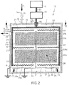
- FIG. 2 shows a device 10 according to the invention
- Cross section provided substantially square anode 11, for example can be cubic, but basically also cylindrical.
- the anode 11 is grounded.
- the anode 11 surrounds a substantially closed interior 12, which the Represents vacuum chamber.
- the anode 11 has a first opening 13, through which is a working gas 14, controlled by a throttle valve 15 in the Vacuum chamber 12 arrives.
- working gas or so-called neutral gas depending on Purpose for example argon, helium, oxygen, nitrogen, Hydrogen, hydrogen peroxide and mixtures of these gases are also considered.
- neutral gas for example argon, helium, oxygen, nitrogen, Hydrogen, hydrogen peroxide and mixtures of these gases are also considered.
- Other gases or gas mixtures are possible.
- the anode 11 has a second opening 16 through which High frequency power is introduced into the vacuum chamber 12.
- the High-frequency power is generated in an HF generator 17 and via a Tuning network 18 passed to a vacuum feedthrough 19.
- the high frequency generator is located 17 and the tuning network 18 outside the vacuum chamber 12.
- the matching network 18 is designed so that a The reflected power is minimized.
- coaxial lines 25 are not only between the HF generator 17 and the tuning network 18 or between the tuning network 18 and the vacuum current feedthrough 19 are arranged are, but, as can be seen in particular from FIG. 2, also within the Vacuum chamber 12 run.
- the high frequency generator 17 can have a power density in the Generate process space between 0.01 and 100 W per liter.
- the voting network 18 is able to reduce the reflected power to less than 2% minimize coupled power.
- the high-frequency power introduced is via 50-ohm coaxial lines 25 to the electrode plates 27 within the vacuum chamber 12 equally distributed.
- the energy required for plasma generation is generated by the high-frequency generator 17 in a frequency between 10 kHz and 100 MHz provided. Due to postal restrictions one uses in the Usually a frequency of 13.56 MHz.
- the adjustment of the high frequency power takes place by means of the voting network 18.
- a third opening 26 represents a gas outlet which is not one shown vacuum pump arranged on the left in FIG. 2 in the gas flow connected is.
- the flow of the working gas thus essentially takes place along arrows P1 and P2.
- the vacuum pump, not shown, as well as a Throttle valve 15 are used to control the typically up to 10 mbar amount of gas pressure.
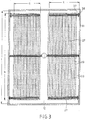
- Each electrode sheet 27 has one, as is 3 results, in particular, with a substantially rectangular cross section a narrow side a and a broad side b.
- the six are essentially identical Electrode sheets 27 arranged one above the other so that the Process space 28, which is shown in FIG. 2 essentially from the inner surface F of the Anode 11 is limited, divided into four sub-process spaces 29a, 29b, 29c, 29d.
- a transport carriage 30 is arranged within the vacuum chamber 12, which comprises a horizontal base plate 31, which on rollers 32 on the Bottom surface 33 of the anode 11 is mounted. Extends from the bottom plate 31 a beam 34 extends substantially vertically upward. On the support element 34, four transport baskets 35a, 35b, 35c, 35d are attached.
- the workpieces to be treated by plasma generation for example should be cleaned, sterilized or surface treated, are located in the transport baskets 35a, 35b, 35c, 35d of the transport carriage 30.
- the trolley 30 is loaded outside of the vacuum chamber 12 discharged.
- the transport baskets 35a, 35b, 35c, 35d protrude in the vacuum chamber 12 transport car 30 located in the corresponding sub-process rooms 29a, 29b, 29c, 29d.
- each pocket-like chamber 36 forms one Single hollow cathode, within which a hollow cathode effect can take place.
- brackets 37 provided that are attached to the anode 11 via insulation pieces 38.
- the brackets 37 for example made of metal, can thus be of the Anode 11 can be arranged electrically insulated.
- electrode plates 27 can have their two ends on the Brackets 37 can be mounted at both ends, so that a stable arrangement is possible becomes.
- the electrode sheets 27 have perforations 39.
- the importance of perforations is said to the following description of the pocket-like chambers also To be received.
- FIG. 4 shows a cutout area of an electrode sheet 27 and of a corner area of an anode 11 Power generated by the high frequency generator 17 on It should be pointed out that the representation according to FIG. 4 is strong is schematized.
- the electrode sheet 27 is shaped such that a plurality of pocket-like chambers 36 lies side by side.
- the electrode plate 27 was converted into a form in which there was a sawtooth-like cross section. This has the advantage that a first pocket-like chamber 40a by side by side arrangement with a second chamber 40b has an M-shaped cross section according to FIG. 4. at the opposite approach results in an essentially W-shaped Cross-section.
- This arrangement has the advantage that between the two pocket-like chambers 40a and 40b, a third, in the embodiment in essentially similarly dimensioned pocket-like chamber 40c is formed.
- two sub-process spaces 29a and 29d can be influenced as follows: 4, the movement path of an electron according to arrow path 41 is shown schematically in the second pocket-like chamber 40b.
- a path can be understood by a physical description of a pocket-like arrangement 40b by means of a potential well, the two legs 42a, 42b of the pocket-like chambers representing infinitely high potential well walls at which the electron is reflected.
- Perforations 39 which are only indicated in Fig. 3, allow a particularly advantageous exchange of charge carriers by the Electrode sheets 27 through.
- pocket-like chambers on either side of one 4 in FIG. 4 directed towards E offers the possibility of that away from this center plane E to either side of the electrode assembly 27 multiple electron collisions can take place.
- the length Z of the legs of the pocket-like chambers 36 as well Angles ⁇ are initially arbitrary.
- the leg length Z is advantageously approximately in the range between 1 and 30 cm and the angle ⁇ in a range of 30 to 150 °.
- each pocket-like chamber 36 or 40a, 40b, 40c an open side has that to a process room, here to the process room 29d is executed.
- FIG. 5 shows one Arrangement of pocket-like chambers, which are essentially along a Sin curve. In particular, this offers the possibility of a Electrode sheet easily corrugated to the pocket-like chambers to create.
- the pocket-like chambers 36 by processing a flat sheet be generated. It is advantageously an aluminum sheet. It other metals are also possible.
- FIG. 6 shows an alternative arrangement of pocket-like chambers 36, which have a substantially rectangular cross section. Here are from a central center plate 43 a plurality of Vertical sheets 44 attached. This arrangement also delivers satisfactory Results.
- the pocket-like Chambers 36 are only indicated by side walls and the chamber bottom is not completely closed.
- FIG. 7 shows another configuration of a cathode assembly 27 which here, however, is not designed as a single sheet.
- the pocket-like Chambers 36 are produced here by only 43 from a central plate vertical plates go off to one side of a process space 29a and pocket-like chambers 36 are formed.
- FIG. 7 An arrangement according to FIG. 7 occurs, for example, in the area of Inner surface F of an anode 11 into consideration, in which the available one Space 45 between the anode 11 and the center plate 43 is too small for that the arrangement of a process room would make sense here.
- the special arrangement of electrode sheets shown in FIG. 2 27 is only exemplary. Basically, a variety of other sub-process rooms 29 by dividing a large process space 28 through an almost arbitrary arrangement of the cathodes 27 can be achieved.
- a hollow cathode effect occurs over a very large pressure range between 0.01 mbar and several mbar.
- the hollow cathode effect occurs on both sides of the cathode assembly 27. Basically they are Dimensions of the pocket-like chambers freely selectable.
- the trolley 30 electrically Is electrically connected to the anode 11
- the electrically grounded serves Dolly 30 including its baskets 35a, 35b, 35c, 35d as well the grounded chamber as an anode.
Landscapes
- Physics & Mathematics (AREA)
- Engineering & Computer Science (AREA)
- Plasma & Fusion (AREA)
- Chemical & Material Sciences (AREA)
- Analytical Chemistry (AREA)
- Plasma Technology (AREA)
- Physical Vapour Deposition (AREA)
Abstract
Description
- Fig. 1
- schematisch eine Vorrichtung des Standes der Technik,
- Fig. 2
- in schematischer, teilgeschnittener Ansicht ein erstes Ausführungsbeispiel der erfindungsgemäßen Vorrichtung mit einem darin eingebrachten Transportwagen,
- Fig. 3
- schematisch eine teilgeschnittene Ansicht der Vorrichtung etwa gemäß Schnittlinie III-III in Fig. 2,
- Fig. 4
- schematisch einen Teilbereich eines Prozeßraums mit Kathode und einem Teilbereich der Anode,
- Fig. 5
- ein zweites Ausführungsbeispiel einer Kathode in Sinusform,
- Fig. 6
- ein drittes Ausführungsbeispiel einer Kathode mit im wesentlichen rechteckförmigen; kammerartigen Taschen, die zu unterschiedlichen Sub-Prozeßräumen hingerichtet sind, und
- Fig. 7
- ein viertes Ausführungsbeispiel einer Kathode mit im Querschnitt rechteckigförmigen kammerartigen Taschen, die zu einem Prozeßraum hingerichtet sind.
Gemäß Fig. 4 ist in der zweiten taschenartigen Kammer 40b schematisch die Bewegungsbahn eines Elektrons gemäß Pfeilbahn 41 dargestellt. Eine derartige Bahn wird verständlich durch eine physikalische Beschreibung einer taschenartigen Anordnung 40b durch einen Potentialtopf, wobei die beiden Schenkel 42a, 42b der taschenartigen Kammern unendlich hohe Potentialtopfwände darstellen, an denen das Elektron reflektiert wird. Auf Grund der dargestellten Wellenbewegung des Elektrons im elektrischen Feld der Hohlkathode ist der Weg des Elektrons wesentlich länger als bei bekannten, konventionellen planaren Elektrodengeometrien. Daraus ergibt sich eine erhöhte Rate für lonisations- und Anregungsstöße zwischen Elektronen und schweren Teilchen und somit eine höhere Plasmadichte bei gleicher angekoppelter Leistung.
Claims (28)
- Vorrichtung (10) zur Erzeugung eines Niedertemperatur-Plasmas (24), umfassend eine hohle Anode (11), die eine im wesentlichen geschlossene Vakuumkammer (12) definiert, innerhalb welcher wenigstens eine Kathodenanordnung (27) vorgesehen ist, welche einen Prozeßraum (28) zumindest teilweise begrenzt, dadurch gekennzeichnet, daß die Kathodenanordnung (27) eine Vielzahl von zu dem Prozeßraum (28, 28a, 28b, 28c, 28d) hin offenen, taschenartigen Kammern (36, 40a, 40b, 40c) umfasst, die eine Vielzahl von Einzel-Hohlkathoden bilden.
- Vorrichtung nach Anspruch 1, dadurch gekennzeichnet, daß zumindest einige taschenartige Kammern (36, 40a, 40b, 40c) nahe der inneren Wandflächen (F) der Anode (11) angeordnet sind.
- Vorrichtung nach einem der vorangegangenen Ansprüche,
dadurch gekennzeichnet, daß mehrere taschenartige Kammern (36, 40a, 40b, 40c) entlang einer Ebene (E) angeordnet sind. - Vorrichtung nach einem der vorangegangenen Ansprüche,
dadurch gekennzeichnet, daß die taschenartigen Kammern (36, 40a, 40b, 40c) entlang unterschiedlicher Ebenen (E) angeordnet sind. - Vorrichtung nach Anspruch 4, dadurch gekennzeichnet, daß die Ebenen (E) parallel zueinander angeordnet sind.
- Vorrichtung nach einem der vorangegangenen Ansprüche,
dadurch gekennzeichnet, daß die Kathodenanordnung von mindestens einem gefalteten oder gewellten Elektrodenblech (27) gebildet wird, welches die taschenartigen Kammern (36, 40a, 40b, 40c) aufweist. - Vorrichtung nach einem der vorangegangenen Ansprüche,
dadurch gekennzeichnet, daß Prozeßraum (28) von der Kathodenanordnung (27) in mehrere Sub-Prozeßräume (29a, 29b, 29c, 29d) unterteilt ist. - Vorrichtung nach Anspruch 7, dadurch gekennzeichnet, daß wenigstens eine taschenartige Kammer (40c) mit ihrer offenen Seite (46) zu einem ersten Sub-Prozeßraum (29d) hingerichtet ist und wenigstens eine weitere taschenartige Kammer (40a, 40b) mit ihrer offenen Seite zu einem zweiten Sub-Prozeßraum (29a) hingerichtet ist.
- Vorrichtung nach einem der vorangegangenen Ansprüche,
dadurch gekennzeichnet, daß jeweils zwei benachbarte taschenartige Kammern (40a, 40b) unter Ausbildung einer im wesentlichen W-förmigen Struktur miteinander verbunden sind. - Vorrichtung nach einem der vorangegangenen Ansprüche, dadruch gekennzeichnet, daß eine erste und eine zweite taschenartige Kammer (40a, 40b) nebeneinander derart angeordnet sind, daß sie zwischen sich eine dritte, entgegengesetzt gerichtete Kammer (40c) ausbilden.
- Vorrichtung nach einem der vorangegangenen Ansprüche,
dadurch gekennzeichnet, daß die Vakuumkammer (12) mittels einer Tür, die Zugang zu dem Prozeßraum (28) bietet, verschließbar ist. - Vorrichtung nach einem der vorangegangenen Ansprüche, dadurch gekennzeichnet, daß innerhalb des Prozeßraums (28) ein Transportwagen (30) anordenbar ist.
- Vorrichtung nach Anspruch 12, dadurch gekennzeichnet, daß der Transportwagen (30) im Prozeßraum (28) geerdet, insbesondere mit der Anode elektrisch verbunden, angeordnet ist.
- Vorrichtung nach Anspruch 13, dadurch gekennzeichnet, daß die Erdung des Transportwagens (30) über einen Kontakt der Rollen (32) des Transportwagens (30) mit der Anode (11) oder über einen Schleifkontakt erfolgt.
- Vorrichtung nach Anspruch 12, dadurch gekennzeichnet, daß der Transportwagen (30) im Prozeßraum (28) elektrisch von der Anode (11) isoliert angeordnet ist.
- Vorrichtung nach einem der Ansprüche 12 bis 15, dadurch gekennzeichnet, daß der Transportwagen (30) mehrere Transportkörbe (35a, 35b, 35c, 35d) umfaßt.
- Vorrichtung nach Anspruch 16, dadurch gekennzeichnet, daß die Anordnung der Transportkörbe (35a, 35b, 35c, 35d) einer Anordnung von Sub-Prozeßräumen (29a, 29b, 29c, 29d) entspricht.
- Vorrichtung nach einem der vorangegangenen Ansprüche,
dadurch gekennzeichnet, daß die taschenartige Kammer (36, 40a, 40b, 40c) im Querschnitt im wesentlichen dreieckförmig ausgebildet ist. - Vorrichtung nach Anspruch 18, dadurch gekennzeichnet, daß die taschenartige Kammer (36, 40a, 40b, 40c) von zwei Schenkelflächen (42a, 42b) gebildet ist, die unter einem Winkel (α) im Bereich zwischen 30 und 150° zueinander stehen.
- Vorrichtung nach Anspruch 18 oder 19, dadurch gekennzeichnet, daß die Schenkellänge (Z) eines Dreiecks im Bereich zwischen 0,5 und 30 cm liegt.
- Vorrichtung nach einem der vorangegangenen Ansprüche,
dadurch gekennzeichnet, daß die taschenartigen Kammern (36, 40a, 40b, 40c) Perforationen (39) aufweisen. - Vorrichtung nach Anspruch 21, dadurch gekennzeichnet, daß die Fläche der Perforationen (39) einen Anteil an der Gesamtfläche der Wände (42a, 42b) der taschenartigen Kammern (36, 40a, 40b, 40c) von weniger als 80 % besitzen.
- Vorrichtung nach einem der vorangegangenen Ansprüche,
dadurch gekennzeichnet, daß die taschenartigen Kammern zylindrisch langgestreckt ausgebildet sind. - , Vorrichtung nach Anspruch 23, dadurch gekennzeichnet, daß die Länge (b) der taschenartigen Kammern (36, 40a, 40b; 40c) nur geringfügig kürzer ist als die Länge (L) der Vakuumkammer (12).
- Vorrichtung nach einem der vorangegangenen Ansprüche,
dadurch gekennzeichnet, daß die taschenartigen Kammern (36, 40a, 40b, 40c) über besondere Halterungen (37) elektrisch isoliert von.der Anode (11) an der Anode (11) befestigt sind. - Vorrichtung nach einem der vorangegangenen Ansprüche,
dadurch gekennzeichnet, daß von einer Hochfrequenzquelle (18), betrieben mit einer Frequenz zwischen 10 kHz und 100 MHz, Hochfrequenzleistung über Koaxial-Leitungen (25) an die taschenartigen Kammern (36, 40a, 40b, 40c) geleitet wird. - Vorrichtung nach Anspruch 26, dadurch gekennzeichnet, daß innerhalb der Vakuumkammer (12) Koaxial-Leitungen (25), insbesondere 50-Ohm-Koaxial-Leitungen (25) zur Leitung der Hochfrequenzleistung an die taschenartigen Kammern (36, 40a, 40b, 40c) angeordnet sind.
- Vorrichtung nach einem der vorangegangenen Ansprüche,
dadurch gekennzeichnet, daß das Plasma (24) gepulst ist.
Applications Claiming Priority (2)
| Application Number | Priority Date | Filing Date | Title |
|---|---|---|---|
| DE10120405 | 2001-04-25 | ||
| DE10120405A DE10120405B4 (de) | 2001-04-25 | 2001-04-25 | Vorrichtung zur Erzeugung eines Niedertemperatur-Plasmas |
Publications (3)
| Publication Number | Publication Date |
|---|---|
| EP1253621A2 true EP1253621A2 (de) | 2002-10-30 |
| EP1253621A3 EP1253621A3 (de) | 2008-01-23 |
| EP1253621B1 EP1253621B1 (de) | 2011-10-05 |
Family
ID=7682765
Family Applications (1)
| Application Number | Title | Priority Date | Filing Date |
|---|---|---|---|
| EP02008643A Expired - Lifetime EP1253621B1 (de) | 2001-04-25 | 2002-04-17 | Vorrichtung zur Erzeugung eines Niedertemperatur-Plasmas |
Country Status (2)
| Country | Link |
|---|---|
| EP (1) | EP1253621B1 (de) |
| DE (1) | DE10120405B4 (de) |
Cited By (5)
| Publication number | Priority date | Publication date | Assignee | Title |
|---|---|---|---|---|
| DE102005045504A1 (de) * | 2005-09-23 | 2007-04-05 | Membrana Gmbh | Verfahren zur Sterilisation von Membranen |
| CN101752171B (zh) * | 2008-12-10 | 2011-12-07 | 财团法人工业技术研究院 | 阴极放电装置 |
| US8198793B2 (en) | 2008-11-19 | 2012-06-12 | Industrial Technology Research Institute | Cathode discharge apparatus |
| RU2496283C1 (ru) * | 2012-03-11 | 2013-10-20 | Федеральное государственное бюджетное учреждение науки Институт систем обработки изображений Российской академии наук (ИСОИ РАН) | Генератор широкоаппертурного потока газоразрядной плазмы |
| US9204950B2 (en) | 2013-08-16 | 2015-12-08 | Industrial Technology Research Institute | Plasma generator, surface treatment method using the same and surface treatment method using the same for bio-tissue |
Families Citing this family (4)
| Publication number | Priority date | Publication date | Assignee | Title |
|---|---|---|---|---|
| DE102010027570B3 (de) | 2010-07-19 | 2011-11-10 | Eagleburgmann Germany Gmbh & Co. Kg | Faltenbalg-Kompensator |
| DE102011084052B4 (de) | 2011-10-05 | 2024-05-29 | Federal-Mogul Burscheid Gmbh | Beschichteter Kolbenring mit scharfer Ölabstreifkante |
| DE102011084051B4 (de) | 2011-10-05 | 2020-03-12 | Federal-Mogul Burscheid Gmbh | Beschichteter Kolbenring mit radial zunehmender Schichtdicke und Verfahren zu dessen Herstellung |
| RU2711344C1 (ru) * | 2019-06-10 | 2020-01-16 | Федеральное государственное бюджетное образовательное учреждение высшего образования "Кубанский государственный технологический университет" (ФГБОУ ВО "КубГТУ") | Устройство источника плазмы несамостоятельного газового разряда с эффектом полого катода |
Family Cites Families (9)
| Publication number | Priority date | Publication date | Assignee | Title |
|---|---|---|---|---|
| US878425A (en) * | 1907-06-17 | 1908-02-04 | William Henry Rines | Electrolytic apparatus for electrolysis of metallic salts. |
| DE3029339C2 (de) * | 1979-09-14 | 1984-11-22 | Hitachi, Ltd., Tokio/Tokyo | Glimmentladungs-Oberflächenbehandlungsverfahren und -vorrichtung |
| US4637853A (en) * | 1985-07-29 | 1987-01-20 | International Business Machines Corporation | Hollow cathode enhanced plasma for high rate reactive ion etching and deposition |
| DE4233895C2 (de) * | 1992-10-08 | 1996-11-28 | Juergen Prof Dr Engemann | Vorrichtung zur Behandlung von durch einen Wickelmechanismus bewegten bahnförmigen Materialien mittels eines reaktiven bzw. nichtreaktiven, durch Hochfrequenz- oder Pulsentladung erzeugten Niederdruckplasmas |
| DE19722624C2 (de) * | 1997-05-30 | 2001-08-09 | Je Plasmaconsult Gmbh | Vorrichtung zur Erzeugung einer Vielzahl von Niedertemperatur-Plasmajets |
| DE19755902C1 (de) * | 1997-12-08 | 1999-05-12 | Fraunhofer Ges Forschung | Verfahren und Vorrichtung zum Vergüten von Oberflächen |
| DE19804838A1 (de) * | 1998-01-29 | 1999-08-05 | Inst Angewandte Chemie Berlin | Verfahren zur plasmagestützten Oberflächenwandlung teilchenförmiger Stoffe sowie Hohlkathoden-Plasmaquelle |
| US6066826A (en) * | 1998-03-16 | 2000-05-23 | Yializis; Angelo | Apparatus for plasma treatment of moving webs |
| EP1141996A1 (de) * | 1998-12-07 | 2001-10-10 | E.I. Du Pont De Nemours And Company | Hohlkathodenmatrix für plasmaerzeugung |
-
2001
- 2001-04-25 DE DE10120405A patent/DE10120405B4/de not_active Expired - Fee Related
-
2002
- 2002-04-17 EP EP02008643A patent/EP1253621B1/de not_active Expired - Lifetime
Cited By (5)
| Publication number | Priority date | Publication date | Assignee | Title |
|---|---|---|---|---|
| DE102005045504A1 (de) * | 2005-09-23 | 2007-04-05 | Membrana Gmbh | Verfahren zur Sterilisation von Membranen |
| US8198793B2 (en) | 2008-11-19 | 2012-06-12 | Industrial Technology Research Institute | Cathode discharge apparatus |
| CN101752171B (zh) * | 2008-12-10 | 2011-12-07 | 财团法人工业技术研究院 | 阴极放电装置 |
| RU2496283C1 (ru) * | 2012-03-11 | 2013-10-20 | Федеральное государственное бюджетное учреждение науки Институт систем обработки изображений Российской академии наук (ИСОИ РАН) | Генератор широкоаппертурного потока газоразрядной плазмы |
| US9204950B2 (en) | 2013-08-16 | 2015-12-08 | Industrial Technology Research Institute | Plasma generator, surface treatment method using the same and surface treatment method using the same for bio-tissue |
Also Published As
| Publication number | Publication date |
|---|---|
| DE10120405A1 (de) | 2002-10-31 |
| EP1253621B1 (de) | 2011-10-05 |
| EP1253621A3 (de) | 2008-01-23 |
| DE10120405B4 (de) | 2008-08-21 |
Similar Documents
| Publication | Publication Date | Title |
|---|---|---|
| DE19856307C1 (de) | Vorrichtung zur Erzeugung eines freien kalten Plasmastrahles | |
| DE69926356T2 (de) | Das verfahren zur erzeugung einer physikalisch und chemisch aktiven umgebung durch einen plasmastrahl und plasmastrahl dazu | |
| DE4301189C2 (de) | Vorrichtung zum Beschichten von Substraten | |
| EP2839500B1 (de) | Mikrowellenplasmaerzeugungsvorrichtung und verfahren zu deren betrieb | |
| EP2849204B1 (de) | Plasmaerzeugungsvorrichtung | |
| DE19722624C2 (de) | Vorrichtung zur Erzeugung einer Vielzahl von Niedertemperatur-Plasmajets | |
| EP1253621B1 (de) | Vorrichtung zur Erzeugung eines Niedertemperatur-Plasmas | |
| DE29615190U1 (de) | Anlage zur Beschichtung von Werkstücken | |
| EP1290926B1 (de) | Hochfrequenz-plasmaquelle | |
| DE4233895C2 (de) | Vorrichtung zur Behandlung von durch einen Wickelmechanismus bewegten bahnförmigen Materialien mittels eines reaktiven bzw. nichtreaktiven, durch Hochfrequenz- oder Pulsentladung erzeugten Niederdruckplasmas | |
| WO1998010114A1 (de) | Verfahren und vorrichtung zur beschichtung von substraten mittels gasflusssputtern | |
| DE102013107659B4 (de) | Plasmachemische Beschichtungsvorrichtung | |
| DE102008027363B4 (de) | Vorrichtung zur Behandlung großvolumiger Substrate im Plasma und Verfahren zur Anwendung | |
| EP0724026B1 (de) | Verfahren zur reaktiven Schichtabscheidung | |
| DE102011111884B3 (de) | Verfahren und Vorrichtung zur Erzeugung von thermodynamisch kaltem Mikrowellenplasma | |
| DD263648B5 (de) | Einrichtung zur erzeugungs eines Mikrowellenplasmas mit grosser Ausdehnung und Homogenitaet | |
| DE19804838A1 (de) | Verfahren zur plasmagestützten Oberflächenwandlung teilchenförmiger Stoffe sowie Hohlkathoden-Plasmaquelle | |
| EP0371252A1 (de) | Verfahren und Vorrichtung zum Ätzen von Substraten mit einer magnetfeldunterstützten Niederdruck-Entladung | |
| WO2000012775A1 (de) | Verfahren und vorrichtung zur beschichtung von substraten im vakuum | |
| WO2024260941A1 (de) | Beschichtungsvorrichtung und ein verfahren zum betreiben einer beschichtungsvorrichtung | |
| DE10008482A1 (de) | Hochfrequenz-Plasmaquelle | |
| WO2001054164A1 (de) | Einkoppelanordnung für mikrowellenenergie mit impedanzanpassung | |
| DE102005049266B4 (de) | Vorrichtung und Verfahren zur Plasmabehandlung von Objekten | |
| EP1114201B1 (de) | Vorrichtung und verfahren zur plasmabehandlung von gegenständen im vakuum | |
| EP3900011B1 (de) | Magnetanordnung für eine plasmaquelle zur durchführung von plasmabehandlungen |
Legal Events
| Date | Code | Title | Description |
|---|---|---|---|
| PUAI | Public reference made under article 153(3) epc to a published international application that has entered the european phase |
Free format text: ORIGINAL CODE: 0009012 |
|
| AK | Designated contracting states |
Kind code of ref document: A2 Designated state(s): AT BE CH CY DE DK ES FI FR GB GR IE IT LI LU MC NL PT SE TR |
|
| AX | Request for extension of the european patent |
Free format text: AL;LT;LV;MK;RO;SI |
|
| PUAL | Search report despatched |
Free format text: ORIGINAL CODE: 0009013 |
|
| AK | Designated contracting states |
Kind code of ref document: A3 Designated state(s): AT BE CH CY DE DK ES FI FR GB GR IE IT LI LU MC NL PT SE TR |
|
| AX | Request for extension of the european patent |
Extension state: AL LT LV MK RO SI |
|
| 17P | Request for examination filed |
Effective date: 20080211 |
|
| AKX | Designation fees paid |
Designated state(s): BE CH DE FR IT LI NL |
|
| 17Q | First examination report despatched |
Effective date: 20090407 |
|
| RAP1 | Party data changed (applicant data changed or rights of an application transferred) |
Owner name: REINHAUSEN PLASMA GMBH |
|
| GRAP | Despatch of communication of intention to grant a patent |
Free format text: ORIGINAL CODE: EPIDOSNIGR1 |
|
| GRAS | Grant fee paid |
Free format text: ORIGINAL CODE: EPIDOSNIGR3 |
|
| GRAA | (expected) grant |
Free format text: ORIGINAL CODE: 0009210 |
|
| AK | Designated contracting states |
Kind code of ref document: B1 Designated state(s): BE CH DE FR IT LI NL |
|
| REG | Reference to a national code |
Ref country code: CH Ref legal event code: EP |
|
| REG | Reference to a national code |
Ref country code: CH Ref legal event code: NV Representative=s name: ROTTMANN, ZIMMERMANN + PARTNER AG |
|
| REG | Reference to a national code |
Ref country code: NL Ref legal event code: T3 |
|
| REG | Reference to a national code |
Ref country code: DE Ref legal event code: R096 Ref document number: 50215226 Country of ref document: DE Effective date: 20111229 |
|
| PLBE | No opposition filed within time limit |
Free format text: ORIGINAL CODE: 0009261 |
|
| STAA | Information on the status of an ep patent application or granted ep patent |
Free format text: STATUS: NO OPPOSITION FILED WITHIN TIME LIMIT |
|
| 26N | No opposition filed |
Effective date: 20120706 |
|
| REG | Reference to a national code |
Ref country code: DE Ref legal event code: R097 Ref document number: 50215226 Country of ref document: DE Effective date: 20120706 |
|
| PGFP | Annual fee paid to national office [announced via postgrant information from national office to epo] |
Ref country code: DE Payment date: 20140429 Year of fee payment: 13 Ref country code: NL Payment date: 20140417 Year of fee payment: 13 Ref country code: CH Payment date: 20140422 Year of fee payment: 13 Ref country code: IT Payment date: 20140424 Year of fee payment: 13 Ref country code: FR Payment date: 20140416 Year of fee payment: 13 |
|
| PGFP | Annual fee paid to national office [announced via postgrant information from national office to epo] |
Ref country code: BE Payment date: 20140417 Year of fee payment: 13 |
|
| REG | Reference to a national code |
Ref country code: DE Ref legal event code: R119 Ref document number: 50215226 Country of ref document: DE |
|
| REG | Reference to a national code |
Ref country code: CH Ref legal event code: PL |
|
| REG | Reference to a national code |
Ref country code: NL Ref legal event code: MM Effective date: 20150501 |
|
| PG25 | Lapsed in a contracting state [announced via postgrant information from national office to epo] |
Ref country code: DE Free format text: LAPSE BECAUSE OF NON-PAYMENT OF DUE FEES Effective date: 20151103 Ref country code: LI Free format text: LAPSE BECAUSE OF NON-PAYMENT OF DUE FEES Effective date: 20150430 Ref country code: IT Free format text: LAPSE BECAUSE OF NON-PAYMENT OF DUE FEES Effective date: 20150417 Ref country code: CH Free format text: LAPSE BECAUSE OF NON-PAYMENT OF DUE FEES Effective date: 20150430 |
|
| REG | Reference to a national code |
Ref country code: FR Ref legal event code: ST Effective date: 20151231 |
|
| PG25 | Lapsed in a contracting state [announced via postgrant information from national office to epo] |
Ref country code: FR Free format text: LAPSE BECAUSE OF NON-PAYMENT OF DUE FEES Effective date: 20150430 |
|
| PG25 | Lapsed in a contracting state [announced via postgrant information from national office to epo] |
Ref country code: NL Free format text: LAPSE BECAUSE OF NON-PAYMENT OF DUE FEES Effective date: 20150501 |
|
| PG25 | Lapsed in a contracting state [announced via postgrant information from national office to epo] |
Ref country code: BE Free format text: LAPSE BECAUSE OF NON-PAYMENT OF DUE FEES Effective date: 20150430 |