EP1253606B1 - Stick-type ignition coil having improved structure against crack or dielectric discharge - Google Patents
Stick-type ignition coil having improved structure against crack or dielectric discharge Download PDFInfo
- Publication number
- EP1253606B1 EP1253606B1 EP02015927A EP02015927A EP1253606B1 EP 1253606 B1 EP1253606 B1 EP 1253606B1 EP 02015927 A EP02015927 A EP 02015927A EP 02015927 A EP02015927 A EP 02015927A EP 1253606 B1 EP1253606 B1 EP 1253606B1
- Authority
- EP
- European Patent Office
- Prior art keywords
- coil
- central core
- spool
- core
- ignition coil
- Prior art date
- Legal status (The legal status is an assumption and is not a legal conclusion. Google has not performed a legal analysis and makes no representation as to the accuracy of the status listed.)
- Expired - Lifetime
Links
- 229920005989 resin Polymers 0.000 claims description 25
- 239000011347 resin Substances 0.000 claims description 25
- 239000012212 insulator Substances 0.000 claims description 19
- 239000003822 epoxy resin Substances 0.000 description 38
- 229920000647 polyepoxide Polymers 0.000 description 38
- 230000000052 comparative effect Effects 0.000 description 23
- 229920001971 elastomer Polymers 0.000 description 18
- 230000008602 contraction Effects 0.000 description 9
- 230000008859 change Effects 0.000 description 7
- 230000005489 elastic deformation Effects 0.000 description 6
- 239000000806 elastomer Substances 0.000 description 5
- 238000009413 insulation Methods 0.000 description 5
- 238000002485 combustion reaction Methods 0.000 description 3
- 239000000463 material Substances 0.000 description 3
- 238000000034 method Methods 0.000 description 3
- 230000001105 regulatory effect Effects 0.000 description 3
- XUIMIQQOPSSXEZ-UHFFFAOYSA-N Silicon Chemical compound [Si] XUIMIQQOPSSXEZ-UHFFFAOYSA-N 0.000 description 2
- 229910000831 Steel Inorganic materials 0.000 description 2
- 239000011248 coating agent Substances 0.000 description 2
- 238000000576 coating method Methods 0.000 description 2
- 230000000694 effects Effects 0.000 description 2
- 239000013013 elastic material Substances 0.000 description 2
- 238000003780 insertion Methods 0.000 description 2
- 230000037431 insertion Effects 0.000 description 2
- 230000033001 locomotion Effects 0.000 description 2
- 238000000465 moulding Methods 0.000 description 2
- 230000035699 permeability Effects 0.000 description 2
- 230000000717 retained effect Effects 0.000 description 2
- 238000007789 sealing Methods 0.000 description 2
- 229910052710 silicon Inorganic materials 0.000 description 2
- 239000010703 silicon Substances 0.000 description 2
- 239000010959 steel Substances 0.000 description 2
- 238000004804 winding Methods 0.000 description 2
- 229910000976 Electrical steel Inorganic materials 0.000 description 1
- 239000004593 Epoxy Substances 0.000 description 1
- 230000015556 catabolic process Effects 0.000 description 1
- 239000004020 conductor Substances 0.000 description 1
- 230000002950 deficient Effects 0.000 description 1
- 230000001419 dependent effect Effects 0.000 description 1
- 238000011161 development Methods 0.000 description 1
- 230000018109 developmental process Effects 0.000 description 1
- 239000003989 dielectric material Substances 0.000 description 1
- 238000007598 dipping method Methods 0.000 description 1
- 230000005684 electric field Effects 0.000 description 1
- 230000004907 flux Effects 0.000 description 1
- 238000001746 injection moulding Methods 0.000 description 1
- 239000011810 insulating material Substances 0.000 description 1
- 238000010030 laminating Methods 0.000 description 1
- 238000005498 polishing Methods 0.000 description 1
- 230000008569 process Effects 0.000 description 1
- 238000005476 soldering Methods 0.000 description 1
- 229920001187 thermosetting polymer Polymers 0.000 description 1
Images




Classifications
-
- H—ELECTRICITY
- H01—ELECTRIC ELEMENTS
- H01F—MAGNETS; INDUCTANCES; TRANSFORMERS; SELECTION OF MATERIALS FOR THEIR MAGNETIC PROPERTIES
- H01F38/00—Adaptations of transformers or inductances for specific applications or functions
- H01F38/12—Ignition, e.g. for IC engines
-
- H—ELECTRICITY
- H01—ELECTRIC ELEMENTS
- H01F—MAGNETS; INDUCTANCES; TRANSFORMERS; SELECTION OF MATERIALS FOR THEIR MAGNETIC PROPERTIES
- H01F27/00—Details of transformers or inductances, in general
- H01F27/28—Coils; Windings; Conductive connections
- H01F27/32—Insulating of coils, windings, or parts thereof
- H01F27/327—Encapsulating or impregnating
-
- H—ELECTRICITY
- H01—ELECTRIC ELEMENTS
- H01F—MAGNETS; INDUCTANCES; TRANSFORMERS; SELECTION OF MATERIALS FOR THEIR MAGNETIC PROPERTIES
- H01F38/00—Adaptations of transformers or inductances for specific applications or functions
- H01F38/12—Ignition, e.g. for IC engines
- H01F2038/122—Ignition, e.g. for IC engines with rod-shaped core
-
- H—ELECTRICITY
- H01—ELECTRIC ELEMENTS
- H01F—MAGNETS; INDUCTANCES; TRANSFORMERS; SELECTION OF MATERIALS FOR THEIR MAGNETIC PROPERTIES
- H01F38/00—Adaptations of transformers or inductances for specific applications or functions
- H01F38/12—Ignition, e.g. for IC engines
- H01F2038/125—Ignition, e.g. for IC engines with oil insulation
-
- H—ELECTRICITY
- H01—ELECTRIC ELEMENTS
- H01F—MAGNETS; INDUCTANCES; TRANSFORMERS; SELECTION OF MATERIALS FOR THEIR MAGNETIC PROPERTIES
- H01F27/00—Details of transformers or inductances, in general
- H01F27/02—Casings
- H01F27/022—Encapsulation
Definitions
- the present invention relates to an ignition coil for an internal combustion engine and, more particularly, to a stick-type ignition coil to be fitted directly in the plug hole of an internal combustion engine.
- a stick-type ignition coil As an ignition coil, a stick-type ignition coil is known. It has a rod-shaped central core disposed in a housing, and a primary coil and a secondary coil wound respectively on a primary spool and a secondary spool made of resin. Resin is filled in the housing of the ignition coil as an electric insulator.
- the insulator not only provides electric insulation among individual members in the housing but also fills clearances between wires of the coils thereby to restrict movements or breakage of the coils which may arise from engine vibrations.
- a thermosetting resin such as epoxy is used in consideration of the heat resistance.
- the ignition coil further has a permanent magnet attached to at least one of the two longitudinal ends of the central core to raise a voltage to be supplied to a spark ignition plug.
- the central core contacts with not only the resin insulator but also a case member such as a spool enclosing the outer circumference of the central core.
- the central core and the resin insulator or the case member as having different thermal expansion coefficients, may repeat expansions and contractions as the surrounding temperature rises and falls. Then, the resin insulator or the case member, as contacting with the central core, especially the resin insulator or the case member contacting the longitudinal end corners of the central core, may crack which results in defective electric insulation.
- an electric discharge may occur through the cracks between the secondary coil or a high voltage terminal (high voltage side) and the central core (low voltage side). If the discharge occurs between the high voltage side and the central core, the electric insulation between the high voltage side and the central core is broken to lower the voltage to be generated in the secondary coil, thus disabling a generation of desired high voltage.
- the central core and the resin insulator or the case member are caused to repeat the expansions and the contractions by the change in the temperature, the central core is caused to receive a load in the radial direction and in the longitudinal direction from the resin insulator and the case member by the difference in the thermal expansion coefficient. Especially when the central core receives the load in the longitudinal direction, the magnetic permeability of the core may drop causing the magneto-striction which disable generation of a required high voltage.
- EP-A-0 827 163 as prior art under Art. 54(3) EPC discloses an ignition coil for an engine comprising a rod-shaped core, a primary coil and a secondary coil wound coaxially on an outer circumference of the core, a primary spool having the primary coil wound thereon, a secondary spool having the secondary coil wound thereon, an outer core arranged around the outer circumference of the secondary coil and a resin insulator filled around the core.
- the ignition coil has the angled member to cover the inner circumference corner of the longitudinal end of the outer core which is arranged around the outer circumferences of the primary coil and the secondary coil, so that the resin insulator is restricted from coming into direct contact with the inner circumference corner of the outer core.
- the spool may have a flange to be arranged to cover the longitudinal end corner of the outer core, so that the cracks, if caused in the resin insulator in the vicinity of the inner circumference corner of the outer core, will hardly extend to the inner circumference because of being shielded by the outer spool. As a result, the cracks are less likely to reach electric wires connecting the coils and terminals in the ignition coil electrically.
- An ignition coil 10 is fitted, as shown in Fig. 1, in a plug hole (not shown) which is formed in each cylinder head of an internal combustion engine, and is electrically connectable to a spark ignition plug.
- the ignition coil 10 has a cylindrical housing 11 made of a resin, in which an accommodating chamber 11a is formed to accommodate a central core assembly 13, a secondary spool 20, a secondary coil 21, a primary spool 23, a primary coil 24 and an outer core 25.
- the central core assembly 13 is comprised of a core 12, and permanent magnets 14 and 15 arranged at the two longitudinal ends (top and bottom) of the core 12.
- An epoxy resin 26 filled in the accommodating chamber 11a infiltrates between the individual members of the ignition coil 10 to ensure the electric insulations among the members as a resin insulating material.
- the core 12 having a column shape is provided by laminating a thin silicon (Si) steel sheet radially to have a generally circular transverse section.
- the permanent magnets 14 and 15 are magnetized to have a magnetic polarity in the direction opposed to the direction of the magnetic flux which is generated by magnetizing the coils.
- the outer circumference of the core 12 is covered with a cylindrical member 17 made of rubber acting as a first buffer member.
- the cap 19 and the secondary spool 20 construct a case member enclosing the outer circumference of the central core assembly 13.
- the cylindrical member 17 is integrally formed into a cylindrical tube shape, as shown in Fig. 2.
- the cylindrical member 17 is comprised of a cylindrical part 17a, annular or ring parts 17b and 17c formed at the two longitudinal ends (top and bottom) of the cylindrical part 17a and having through holes 18 formed at their centers, and angled parts 17d formed at corners between the cylindrical part 17a and the annular parts 17b and 17c.
- the cylindrical part 17a covers the outer circumference of the central core assembly 13
- the annular parts 17b and 17c cover the portions of the two longitudinal end faces of the central core assembly 13
- the angled parts 17d cover the end corners of the permanent magnets 14 and 15 or the two end corners of the central core assembly 13.
- the annular parts 17b and 17c are made thicker than the cylindrical part 17a to function as a second buffer member.
- the through holes 18 are made diametrically smaller than the permanent magnets 14 and 15 so that the core 12 and the permanent magnets 14 and 15 are fitted into the cylindrical member 17 by expanding diametrically the through holes 18.
- the secondary spool 20 is arranged on the outer circumference of the cylindrical member 17 and is molded of a resin material into such a bottomed cylinder as is closed at the longitudinal end side of the permanent magnet 15.
- the secondary coil 21 is wound on the outer circumference of the secondary spool 20, and a dummy coil 22 is further wound by one turn on the higher voltage side of the secondary coil 21.
- the dummy coil 22 connects the secondary coil 21 and a terminal plate 40 electrically. Since the secondary coil 21 and the terminal plate 40 are electrically connected through not a single but the dummy coil 22, the surface area of the electrically connected portion between the secondary coil 21 and the terminal plate 40 is enlarged to avoid the concentration of electric field at the electrically connected portion.
- the primary spool 23 is arranged on the outer circumference of the secondary coil 21 and is molded of a resin material.
- the primary coil 24 is wound on the outer circumference of the primary spool 23.
- a switching circuit (not shown) for supplying a control signal to the primary coil 24 is disposed outside of the ignition coil 10, and the primary coil 24 is electrically connected with the switching circuit through a terminal which is insert-molded on a connector 30.
- the outer core 25 is mounted on the outer circumference side of the primary coil 24.
- the outer core 25 is provided by winding a thin silicon (Si) steel sheet into a cylindrical shape but does not connect the starting end and the terminal end of the winding to leave a gap in the longitudinal direction.
- the outer core 25 has a longitudinal length from the outer circumference position of the permanent magnet 14 to the outer circumference position of the permanent magnet 15 to form a magnetic circuit.
- a high voltage terminal 41 is insert-molded below the housing 11.
- the central portion of the terminal plate 40 is folded in the direction to insert the high voltage terminal 41 to form a pawl.
- the high voltage terminal 41 is electrically connected with the terminal plate 40 by inserting the leading end of the high voltage terminal 41 into the pawl.
- the wire of the dummy coil 22 at the high voltage end is electrically connected with the terminal plate 40 by fusing or soldering.
- a conductor spring 42 is electrically connected with the high voltage terminal 41 and with the ignition plug when the ignition coil 10 is inserted into the plug hole.
- a plug cap 43 made of rubber, into which the ignition plug is inserted.
- the secondary spool 20 and the epoxy resin 26, as enclosing the central core assembly 13, have a thermal expansion coefficient different from that of the core 12 and the permanent magnets 14 and 15, as constructing the central core assembly 13.
- the thermal expansion coefficient of the secondary spool 20 and the epoxy resin 26 is larger than that of the central core assembly 13.
- the outer circumference of the central core assembly 13 and the end corners of the permanent magnets 14 and 15 are covered with the cylindrical member 17 which is an elastic member so that the outer circumference of the central core assembly 13 and the end corners of the permanent magnets 14 and 15 are prevented from coming into direct contact with the secondary spool 20 and the epoxy resin 26.
- the cylindrical member 17 can elastically deform to absorb the difference in the thermal expansion coefficients.
- the cracks are prevented around the outer circumference of the central core assembly 13 and especially at the secondary spool 20 and the epoxy resin 26 in the vicinity of the two end corners of the central core assembly 13, where the cracks might otherwise be liable to occur, so that the electric discharge between the high voltage side and the central core assembly 13 can be prevented. This makes it possible to apply the desired high voltage to the ignition plug.
- the thermal expansion coefficient of the cap 19, the secondary spool 20 and the epoxy resin 26 is different from or larger than that of the central core assembly 13 comprised of the core 12 and the permanent magnets 14 and 15. As the temperature lowers, therefore, the cap 19, the secondary spool 20 and the epoxy resin 26 contact to activate a force to contract the central core assembly 13 in the radial direction and in the longitudinal direction. Especially when the force is applied in the longitudinal direction of the central core assembly 13, a magneto-striction to lower the magnetic permeability of the core 12 may occur to lower the voltage to be generated in the secondary coil 21.
- the central core assembly 13 Since the central core assembly 13 is covered at its outer circumference with the cylindrical part 17a and partially at its two longitudinal ends with the annular parts 17b and 17c thicker than the cylindrical member 17, however, this cylindrical member 17 is elastically deformed to buffer the forces to be received by the central core assembly 13 in the radial direction and in the longitudinal direction so that no magneto-striction occurs in the core 12. As a result, the desired high voltage can be applied to the ignition plug.
- the permanent magnets 14 and 15 are arranged in the first comparative example at the two longitudinal ends of the core 12, but the permanent magnet may be arranged at only one end of the core 12.
- the cracks can be prevented around the outer circumference of the core 12 and especially at the secondary spool 20 and the epoxy resin 26 in the vicinity of the two end corners of the core 12, where the cracks might otherwise be liable to occur, so that the electric discharge between the high voltage side and the central core assembly 13 can be prevented.
- the desired high voltage can be applied to the ignition plug.
- the cylindrical member 17 made of rubber to act as the first buffer member is comprised of the cylindrical part 17a, an angled part 17b and a bottom disc part 17c acting as a second buffer member, and is shaped into a bottomed cylindrical shape, as closed at the bottom longitudinal end side of the permanent magnet 15.
- the cylindrical part 17a covers the outer circumference of the central core assembly 13
- the annular angled part 17b covers the end corner of the permanent magnet 15
- the disc part 17c covers the bottom end face of the permanent magnet 15.
- the cylindrical member 17 is extended upwardly at the side of the permanent magnet 14 over the end face of the permanent magnet 14.
- a plate member 17e made of rubber to act as the first buffer member and the second buffer member is formed into a disc shape separate from the cylindrical member 17 and has a larger diameter than the permanent magnet 14.
- the end corner of the permanent magnet 14 is covered with the cylindrical member 17 and the plate member 17e, and the longitudinal top end face of the permanent magnet 14 is covered with the plate member 17e.
- this plate member 17e effects a sealing between the cap 19 acting as the case member and the permanent magnet 14 so that the epoxy resin 26 will not enter the central core assembly 13.
- the cracks can be prevented around the outer circumference of the central core assembly 13 and especially at the secondary spool 20 and the epoxy resin 26 in the vicinity of the two end corners of the central core assembly 13, where the cracks might otherwise be liable to occur, so that the electric discharge between the high voltage side and the central core assembly 13 can be prevented.
- the desired high voltage can be applied to the ignition plug.
- the first buffer member is comprised of the cylindrical member 17 and the plate member 17e, and the cylindrical member 17 is formed into the bottomed cylindrical shape having no longitudinal end face at its longitudinal top end, so that the first buffer member can be easily provided.
- the cylindrical member 17, as made of rubber to act as the first buffer member is comprised of the cylindrical part 17a, the angled part 17b and the annular part 17c, and is formed into a cylindrical tube shape.
- the cylindrical part 17a covers the outer circumference of the central core assembly 13
- the annular angled part 17b covers the end corner of the permanent magnet
- the annular part 17c covers a portion of the longitudinal bottom end face of the permanent magnet 15.
- the cylindrical part 17a extends to the circumferential side of the permanent magnet 14, but its end portion falls short of the top end face of the permanent magnet 14.
- Plate members 17f and 17g made of rubber to act as the second buffer member are formed into a circular shape separate from the cylindrical member 17.
- the plate members 17f and 17g are made radially smaller than the permanent magnets 14 and 15 and are in abutment against the longitudinal end faces of the permanent magnets 14 and 15, respectively.
- the end corner of the permanent magnet 14 is surrounded by a space 100 and is kept out of contact with any member. Moreover, the plate member 17f effects a sealing between the cap 19 as the case member and the permanent magnet 14 so that the epoxy resin 26 will not enter the central core assembly 13.
- the end corner of the permanent magnet 14 confronts the space 100, and the end corner of the permanent magnet 15 is covered with the cylindrical member 17, so that the two longitudinal end corners of the central core assembly 13 are out of contact with the secondary spool 20 and the epoxy resin 26.
- the cracks are prevented around the outer circumference of the central core assembly 13 and especially at the secondary spool 20 and the epoxy resin 26 in the vicinity of the two end corners of the central core assembly 13, where the cracks might otherwise be liable to occur, so that the discharge between the high voltage side and the central core assembly 13 can be prevented. This makes it possible to apply the desired high voltage to the ignition plug.
- the plate members 17f and 17g As a result of the elastic deformations of the plate members 17f and 17g, moreover, the forces for the central core assembly 13 to receive in the radial direction and in the longitudinal direction are buffered so that the magneto-striction will not occur in the central core assembly 13. Thus, the desired high voltage can be applied to the ignition plug.
- the plate member 17f as the second buffer member acts as the seal member between the end face of the permanent magnet 14 and the cap 19 so that the number of parts and the number of assembling steps are reduced.
- the cracks are prevented around the outer circumference of the central core and especially at the secondary spool 20 and the epoxy resin 26 in the vicinity of the two longitudinal end corners of the central core, where the cracks might otherwise be liable to occur.
- the discharge between the high voltage side in the ignition coil and the central core or the low voltage side can be prevented, as might otherwise occur along the cracks, so that the desired high voltage can be applied to the ignition plug.
- the outer circumference of the central core assembly 13 is covered with the cylindrical member 17, and the two longitudinal end faces of the central core assembly 13 are covered with either the cylindrical member 17 or the plate members 17e, 17f, 17g acting as the buffer member.
- the cylindrical member 17 and the plate members 17e, 17f, 17g are elastically deformed to buffer the forces to be received by the central core assembly 13 in the radial direction and in the longitudinal direction are buffered. As a result, no magneto-striction will be caused in the central core assembly 13 so that the desired high voltage can be applied to the ignition plug.
- the buffer member 17 acting as the buffer member is extended in the longitudinal direction of the central core assembly 13 and shaped to cover at least one end corner and the outer circumference of the central core assembly 13, the buffer member may be comprised of a plurality of members to cover only the longitudinal end corners of the central core assembly 13.
- cylindrical member 17 and the plate members 17e, 17f, 17g are molded of rubber
- the cylindrical member 17 and the plate members 17e, 17f, 17g can be molded of an elastomer resin, and the cylindrical member 17 can be insert-molded to have the central core assembly 13 integrally therein.
- the central core assembly 13 may be inserted into the cylindrical member 12 which is molded of the elastomer resin.
- the cylindrical member 17 as the buffer member may be provided by covering the surface of the central core assembly 13 with an elastic member of an elastomer resin or rubber by the integral molding method such as the injection molding, baking or dipping method.
- the cylindrical member may cover the whole surface of the central core assembly 13 or may have a small through hole formed at one longitudinal end portion for discriminating the end specified one end portion of the central core assembly 13.
- the cylindrical member 17 may be provided by mounting the permanent magnets 14 and 15 in advance on the core 12 to construct the central core assembly 13 and by covering the central core assembly 13 with a thermally shrinking tube to shrink this tube thermally.
- cylindrical member 17 contacting with the end corners of the central core assembly 13 may be prevented from any damage by chamfering the end corners of the central core assembly 13, i.e., the end corners of the permanent magnets 14 and 15 by polishing or the like.
- a flange 23a which is bulged radially outward and which has a fitting portion 23b formed to have an L-shaped section for fitting a ring member 50a therein.
- the inner circumference corners of the two longitudinal end portions of the outer core 25 are covered with ring members 50b and 50a which are made of rubber to act as angled members.
- the inner circumference of the end portion of the outer core 25, as located at the high voltage side of the secondary coil 21, is covered with the ring member 50, whereas the inner circumference corner of the end portion of the outer core 25, as located at the low voltage side of the secondary coil 21, is covered with the ring member 51.
- the ring member 50a is fitted in the fitting portion 23b which is formed in the flange 23a.
- the internal diameter of the ring member 50a is set to be slightly smaller than the external diameter of the outer circumference of the fitting portion 23b.
- the elastic force of the ring member 50a acts upon the fitting portion 23b inward in the radial direction.
- the ignition coil 10 is assembled as follows.
- the coil assembly including the outer core 25 may be inserted into the transformer portion 11b by assembling the outer core 25 with the coil assembly, and then by covering the inner circumference corner of the end portion of the outer core 25 at the low voltage side in advance with the ring member 51.
- the epoxy resin 26 has a larger thermal expansion coefficient than that of the outer core 25 made of a silicon steel sheet. If the inner circumference corners of the two end portions of the outer core 25 are not covered with the ring members 50b and 50a but are in direct contact with the epoxy resin 26, the ring members 50b and 50a and the epoxy resin 26 repeat the expansions and contractions as the temperature changes, so that cracks will occur in the epoxy resin 26 contacting with the inner circumference corners of the two end portions of the outer core 25.
- a discharge may occur through the cracks between the dummy coil 22, the terminal plate 40 or the high voltage terminal 41 at the high voltage side of the secondary coil 21 or the high voltage side and the outer core 25 or the low voltage portion. With this discharge between the high voltage portion and the low voltage portion, the voltage to be applied to the ignition plug drops so that the desired high voltage cannot be applied to the ignition plug.
- the inner circumference corners of the two end portions of the outer core 25 are covered with the ring members 50b and 50a made of rubber, so that they are prevented from contacting directly with the epoxy resin 26.
- the difference in the expansion coefficient between the outer core 25 and the epoxy resin 26 can be absorbed by the elastic deformations of the ring members 50b and 51.
- no crack occurs in the epoxy resin 26 in the vicinity of the inner circumference corners of the two end portions of the outer core 25 so that the discharge can be suppressed between the high voltage side of the secondary coil 21, i.e., the dummy coil 22, the terminal plate 40 or the high voltage terminal 41 and the outer core 25.
- the desired high voltage can be applied to the ignition plug.
- the ring member 50a can be fitted in the fitting portion 23b of the primary spool 23 so that the ring member 50a is less likely to come out of the primary spool 23 when this primary spool 23 is inserted into the outer core 25. As a result, the assemlability of the ring member 50a is improved to reduce the number of assembling steps.
- the flange 23a in which an annular groove 27b is formed as the fitting portion for fitting the ring member 50c as the angled member.
- the ring member as the angled member covers the inner circumference corners of the two longitudinal end portions of the outer core 25 thereby to prevent the epoxy resin 26 from coming into direct contact with the inner circumference corners of the two end portions of the outer core 25.
- the cracks are suppressed in the epoxy resin 26 in the vicinity of the inner circumference corners of the two end portions of the outer core 25 due to the temperature change.
- the discharge between the high voltage side of the secondary coil 21 or the high voltage portion such as the dummy coil 22, the terminal plate 40 or the high voltage terminal 41 and the outer core 25 or the low voltage portion can be suppressed to apply the desired high voltage to the ignition coil.
- the whole surface of the outer core 25 but only the inner circumference corner of its end portion is covered with the ring member so that the radius of the ignition coil is not enlarged.
- the ring member as the angled member is made of rubber in the fifth embodiment and sixth embodiment, but the rubber may be replaced by an elastomer resin. Moreover, the ring member may be made of a hard resin or the like in place of the elastic material if the inner circumference corner of the end portion of the outer core can be covered with a cured face.
- the angled member is made of a volumetrically shrinkable material such as independently foamed sponge, on the other hand, this sponge is easily deformable so that the sponge abutting against the outer core can be deformed in its section into an L-shape conforming the shape of the inner circumference corner of the end portion of the outer core by applying the outer core to the independently foamed sponge thereby to cover the inner circumference corner of the end portion of the outer core.
- the angled member can be formed in its sectional shape not into the L-shape in advance but into the simple plate shape so that it can be easily worked.
- the ring members cover the inner circumference corners of the two end portions of the outer core 25 in the embodiments but can cover only the inner circumference corner of one end portion of the outer core 25.
- the end portion of the outer core, as located at the low voltage side of the secondary coil, for example, may be covered with a ring member having a C-shaped section.
Landscapes
- Engineering & Computer Science (AREA)
- Power Engineering (AREA)
- Ignition Installations For Internal Combustion Engines (AREA)
- Insulating Of Coils (AREA)
Description
- The present invention relates to an ignition coil for an internal combustion engine and, more particularly, to a stick-type ignition coil to be fitted directly in the plug hole of an internal combustion engine.
- As an ignition coil, a stick-type ignition coil is known. It has a rod-shaped central core disposed in a housing, and a primary coil and a secondary coil wound respectively on a primary spool and a secondary spool made of resin. Resin is filled in the housing of the ignition coil as an electric insulator. The insulator not only provides electric insulation among individual members in the housing but also fills clearances between wires of the coils thereby to restrict movements or breakage of the coils which may arise from engine vibrations. As the insulator, a thermosetting resin such as epoxy is used in consideration of the heat resistance. The ignition coil further has a permanent magnet attached to at least one of the two longitudinal ends of the central core to raise a voltage to be supplied to a spark ignition plug.
- In this type of ignition coil, the central core contacts with not only the resin insulator but also a case member such as a spool enclosing the outer circumference of the central core. The central core and the resin insulator or the case member, as having different thermal expansion coefficients, may repeat expansions and contractions as the surrounding temperature rises and falls. Then, the resin insulator or the case member, as contacting with the central core, especially the resin insulator or the case member contacting the longitudinal end corners of the central core, may crack which results in defective electric insulation.
- When the resin insulator or the case member around the central core cracks, an electric discharge may occur through the cracks between the secondary coil or a high voltage terminal (high voltage side) and the central core (low voltage side). If the discharge occurs between the high voltage side and the central core, the electric insulation between the high voltage side and the central core is broken to lower the voltage to be generated in the secondary coil, thus disabling a generation of desired high voltage.
- If the central core and the resin insulator or the case member are caused to repeat the expansions and the contractions by the change in the temperature, the central core is caused to receive a load in the radial direction and in the longitudinal direction from the resin insulator and the case member by the difference in the thermal expansion coefficient. Especially when the central core receives the load in the longitudinal direction, the magnetic permeability of the core may drop causing the magneto-striction which disable generation of a required high voltage.
- It is desired in a stick-type ignition coil to dispose an outer core around the outer periphery of the primary spool and the secondary spool. Since this outer core contacts directly with the insulator in the housing, the outer core and the insulator having different thermal expansion coefficients, may repeat expansions and contractions as the temperature changes. As a result, the insulator contacting with the outer core may crack causing an electric discharge between the secondary coil or a high voltage terminal the outer core. This discharge lowers the high voltage to be applied to the ignition plug.
- EP-A-0 827 163 as prior art under Art. 54(3) EPC discloses an ignition coil for an engine comprising a rod-shaped core, a primary coil and a secondary coil wound coaxially on an outer circumference of the core, a primary spool having the primary coil wound thereon, a secondary spool having the secondary coil wound thereon, an outer core arranged around the outer circumference of the secondary coil and a resin insulator filled around the core.
- It is an object of the present invention to further develop an ignition coil according to the preamble of claim 1 such that the occurrence of cracks is suppressed.
- According to the invention, this object is achieved by an ignition coil having the features of claim 1.
- Advantageous further developments are set out in the dependent claims.
- According to the invention, it is not only possible to suppress the occurrence of cracks but also a dielectric breakdown caused by a change in the surrounding temperature.
- In another ignition coil disclosed in JP-U-59-30501, although not a stick-type, the corners of the core are covered by over-coating the surface of the core with an elastomer. This prevents the corners of the core and the insulator made of epoxy resin from coming into direct contact with each other and suppresses the cracks in the epoxy resin in the vicinity of the corners of the core. This over coating is not applicable to the stick-type ignition coil, because the stick-type is so regulated in its external diameter as to match the internal diameter of the plug hole.
- According to the invention, the ignition coil has the angled member to cover the inner circumference corner of the longitudinal end of the outer core which is arranged around the outer circumferences of the primary coil and the secondary coil, so that the resin insulator is restricted from coming into direct contact with the inner circumference corner of the outer core. As a result, even if the outer core and the resin insulator having the different expansion coefficients repeat the expansions and contractions as the temperature changes, cracks can be suppressed in the resin insulator in the vicinity of the inner circumference corner of the outer core. As a result, the electric discharge can be suppressed so that the drop in the voltage to be applied to an ignition plug can be restricted. Alternatively, the spool may have a flange to be arranged to cover the longitudinal end corner of the outer core, so that the cracks, if caused in the resin insulator in the vicinity of the inner circumference corner of the outer core, will hardly extend to the inner circumference because of being shielded by the outer spool. As a result, the cracks are less likely to reach electric wires connecting the coils and terminals in the ignition coil electrically.
- The object, features and advantages of the present invention will become more apparent from the following detailed description with reference to the embodiments shown in the accompanying drawings. In the drawings:
- Fig. 1 is a longitudinal sectional view showing an ignition coil according to the first comparative example;
- Fig. 2 is a sectional view showing a cylindrical member used in the first comparative example;
- Fig. 3 is an enlarged sectional view showing one end portion of the ignition coil according to the first comparative example, the one portion being designated by a circle III in Fig. 1;
- Fig. 4 is an enlarged sectional view showing the other end portion of the ignition coil according to the first comparative example, the other portion being designated by a circle IV in Fig. 1;
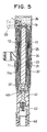
- Fig. 5 is a longitudinal sectional view showing an ignition coil according to the second comparative example;
- Fig. 6 is an enlarged sectional view showing, one end portion of the ignition coil according to the third comparative example;
- Fig. 7 is an enlarged sectional view showing the other end portion of the ignition coil according to the third comparative example;
- Fig. 8 is an enlarged sectional view showing one end portion of an ignition coil according to the fourth comparative example;
- Fig. 9 is an enlarged sectional view showing the other end portion of the ignition coil according to the fourth comparative example;
- Fig. 10 is a sectional view showing an ignition coil according to the first embodiment of the invention;
- Fig. 11 is an enlarged sectional view showing a low voltage side of the ignition coil according to the first embodiment;
- Fig. 12 is a sectional view showing a high voltage side of the ignition coil according to the first embodiment; and
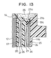
- Fig. 13 is an enlarged sectional view showing the low voltage side of an ignition coil according to a second embodiment of the invention.
- The present invention will be described with reference to various embodiments throughout which the same or like parts are designated by the same or similar reference numerals.
- An
ignition coil 10 is fitted, as shown in Fig. 1, in a plug hole (not shown) which is formed in each cylinder head of an internal combustion engine, and is electrically connectable to a spark ignition plug. - The
ignition coil 10 has acylindrical housing 11 made of a resin, in which anaccommodating chamber 11a is formed to accommodate acentral core assembly 13, asecondary spool 20, asecondary coil 21, aprimary spool 23, aprimary coil 24 and anouter core 25. Thecentral core assembly 13 is comprised of acore 12, andpermanent magnets core 12. Anepoxy resin 26 filled in theaccommodating chamber 11a infiltrates between the individual members of theignition coil 10 to ensure the electric insulations among the members as a resin insulating material. - The
core 12 having a column shape is provided by laminating a thin silicon (Si) steel sheet radially to have a generally circular transverse section. Thepermanent magnets core 12 is covered with acylindrical member 17 made of rubber acting as a first buffer member. On thepermanent magnet 14 covered with thecylindrical member 17, moreover, there is fitted acap 19 having a through hole. Thecap 19 and thesecondary spool 20 construct a case member enclosing the outer circumference of thecentral core assembly 13. - The
cylindrical member 17 is integrally formed into a cylindrical tube shape, as shown in Fig. 2. Thecylindrical member 17 is comprised of acylindrical part 17a, annular orring parts cylindrical part 17a and having throughholes 18 formed at their centers, andangled parts 17d formed at corners between thecylindrical part 17a and theannular parts cylindrical part 17a covers the outer circumference of thecentral core assembly 13, theannular parts central core assembly 13, and theangled parts 17d cover the end corners of thepermanent magnets central core assembly 13. Theannular parts cylindrical part 17a to function as a second buffer member. The through holes 18 are made diametrically smaller than thepermanent magnets core 12 and thepermanent magnets cylindrical member 17 by expanding diametrically the through holes 18. - As shown in Figs. 1 and 3, the
secondary spool 20 is arranged on the outer circumference of thecylindrical member 17 and is molded of a resin material into such a bottomed cylinder as is closed at the longitudinal end side of thepermanent magnet 15. Thesecondary coil 21 is wound on the outer circumference of thesecondary spool 20, and adummy coil 22 is further wound by one turn on the higher voltage side of thesecondary coil 21. Thedummy coil 22 connects thesecondary coil 21 and aterminal plate 40 electrically. Since thesecondary coil 21 and theterminal plate 40 are electrically connected through not a single but thedummy coil 22, the surface area of the electrically connected portion between thesecondary coil 21 and theterminal plate 40 is enlarged to avoid the concentration of electric field at the electrically connected portion. - The
primary spool 23 is arranged on the outer circumference of thesecondary coil 21 and is molded of a resin material. Theprimary coil 24 is wound on the outer circumference of theprimary spool 23. A switching circuit (not shown) for supplying a control signal to theprimary coil 24 is disposed outside of theignition coil 10, and theprimary coil 24 is electrically connected with the switching circuit through a terminal which is insert-molded on aconnector 30. - The
outer core 25 is mounted on the outer circumference side of theprimary coil 24. Theouter core 25 is provided by winding a thin silicon (Si) steel sheet into a cylindrical shape but does not connect the starting end and the terminal end of the winding to leave a gap in the longitudinal direction. Theouter core 25 has a longitudinal length from the outer circumference position of thepermanent magnet 14 to the outer circumference position of thepermanent magnet 15 to form a magnetic circuit. - A
high voltage terminal 41 is insert-molded below thehousing 11. The central portion of theterminal plate 40 is folded in the direction to insert thehigh voltage terminal 41 to form a pawl. Thehigh voltage terminal 41 is electrically connected with theterminal plate 40 by inserting the leading end of thehigh voltage terminal 41 into the pawl. The wire of thedummy coil 22 at the high voltage end is electrically connected with theterminal plate 40 by fusing or soldering. Aconductor spring 42 is electrically connected with thehigh voltage terminal 41 and with the ignition plug when theignition coil 10 is inserted into the plug hole. In the open end of thehousing 11 at the high voltage side, there is mounted aplug cap 43 made of rubber, into which the ignition plug is inserted. When the control signal is fed from the switching circuit to theprimary coil 24, a high voltage is generated and is applied to the ignition plug through thedummy coil 22, theterminal plate 40, thehigh voltage terminal 41 and thespring 42. - In the
ignition coil 10, thesecondary spool 20 and theepoxy resin 26, as enclosing thecentral core assembly 13, have a thermal expansion coefficient different from that of thecore 12 and thepermanent magnets central core assembly 13. Usually, the thermal expansion coefficient of thesecondary spool 20 and theepoxy resin 26 is larger than that of thecentral core assembly 13. As a result, if thecentral core assembly 13 is not covered with thecylindrical member 17 and if thesecondary spool 20 and theepoxy resin 26 are in direct contact with thecentral core assembly 13, thesecondary spool 20 contacting with thecentral core assembly 13 and theepoxy resin 26 may be cracked by the repeated expansions and contractions of thecentral core assembly 13, thesecondary spool 20 and theepoxy resin 26 according to the temperature change. Especially thesecondary spool 20 in contact with the end corners of thepermanent magnets epoxy resin 26 are liable to crack. When thesecondary spool 20 in contact with the end corners of thepermanent magnets epoxy resin 26 crack, an electric discharge may occur through the cracks between thedummy coil 22, theterminal plate 40 or thehigh voltage terminal 41 at the high voltage side of thesecondary coil 21 or the high voltage side and thecentral core assembly 13 or the low voltage side. If this discharge occurs between the high voltage side and thecentral core assembly 13, the insulation between the high voltage side and thecentral core assembly 13 is broken to lower the voltage to be generated at the secondary coil so that the desired high voltage cannot be applied to the ignition plug. - In the first comparative example, however, the outer circumference of the
central core assembly 13 and the end corners of thepermanent magnets cylindrical member 17 which is an elastic member so that the outer circumference of thecentral core assembly 13 and the end corners of thepermanent magnets secondary spool 20 and theepoxy resin 26. Even if thecentral core assembly 13 and thesecondary spool 20 or theepoxy resin 26 having different thermal expansion coefficients repeat expansions and contractions in accordance with the temperature change, moreover, thecylindrical member 17 can elastically deform to absorb the difference in the thermal expansion coefficients. As a result, the cracks are prevented around the outer circumference of thecentral core assembly 13 and especially at thesecondary spool 20 and theepoxy resin 26 in the vicinity of the two end corners of thecentral core assembly 13, where the cracks might otherwise be liable to occur, so that the electric discharge between the high voltage side and thecentral core assembly 13 can be prevented. This makes it possible to apply the desired high voltage to the ignition plug. - The thermal expansion coefficient of the
cap 19, thesecondary spool 20 and theepoxy resin 26 is different from or larger than that of thecentral core assembly 13 comprised of thecore 12 and thepermanent magnets cap 19, thesecondary spool 20 and theepoxy resin 26 contact to activate a force to contract thecentral core assembly 13 in the radial direction and in the longitudinal direction. Especially when the force is applied in the longitudinal direction of thecentral core assembly 13, a magneto-striction to lower the magnetic permeability of the core 12 may occur to lower the voltage to be generated in thesecondary coil 21. Since thecentral core assembly 13 is covered at its outer circumference with thecylindrical part 17a and partially at its two longitudinal ends with theannular parts cylindrical member 17, however, thiscylindrical member 17 is elastically deformed to buffer the forces to be received by thecentral core assembly 13 in the radial direction and in the longitudinal direction so that no magneto-striction occurs in thecore 12. As a result, the desired high voltage can be applied to the ignition plug. - The
permanent magnets core 12. - In the second comparative example shown in Fig. 5, no the permanent magnets are arranged at the two longitudinal ends of the core 12, but the core 12 itself provides the
central core assembly 13. Thecore 12 is covered partially at the outer circumference, at the two end corners and at the two longitudinal end faces with thecylindrical member 17. - In the second comparative example, too, the cracks can be prevented around the outer circumference of the
core 12 and especially at thesecondary spool 20 and theepoxy resin 26 in the vicinity of the two end corners of the core 12, where the cracks might otherwise be liable to occur, so that the electric discharge between the high voltage side and thecentral core assembly 13 can be prevented. As a result, the desired high voltage can be applied to the ignition plug. - As a result of the elastic deformation of the
cylindrical member 17, moreover, the forces for the core 12 to receive in the radial direction and in the longitudinal direction are buffered to establish no magneto-striction in thecore 12. Thus, the desired high voltage can be applied to the ignition plug. - In the third comparative example shown in Figs. 6 and 7, the
cylindrical member 17 made of rubber to act as the first buffer member is comprised of thecylindrical part 17a, anangled part 17b and abottom disc part 17c acting as a second buffer member, and is shaped into a bottomed cylindrical shape, as closed at the bottom longitudinal end side of thepermanent magnet 15. Thecylindrical part 17a covers the outer circumference of thecentral core assembly 13, the annularangled part 17b covers the end corner of thepermanent magnet 15, and thedisc part 17c covers the bottom end face of thepermanent magnet 15. Thecylindrical member 17 is extended upwardly at the side of thepermanent magnet 14 over the end face of thepermanent magnet 14. Aplate member 17e made of rubber to act as the first buffer member and the second buffer member is formed into a disc shape separate from thecylindrical member 17 and has a larger diameter than thepermanent magnet 14. The end corner of thepermanent magnet 14 is covered with thecylindrical member 17 and theplate member 17e, and the longitudinal top end face of thepermanent magnet 14 is covered with theplate member 17e. Moreover, thisplate member 17e effects a sealing between thecap 19 acting as the case member and thepermanent magnet 14 so that theepoxy resin 26 will not enter thecentral core assembly 13. - In the third comparative example, too, the cracks can be prevented around the outer circumference of the
central core assembly 13 and especially at thesecondary spool 20 and theepoxy resin 26 in the vicinity of the two end corners of thecentral core assembly 13, where the cracks might otherwise be liable to occur, so that the electric discharge between the high voltage side and thecentral core assembly 13 can be prevented. As a result, the desired high voltage can be applied to the ignition plug. - As a result of the elastic deformations of the
cylindrical member 17 and theplate member 17e, moreover, the forces for thecentral core assembly 13 to receive in the radial direction and in the longitudinal direction are buffered to establish no magneto-striction in thecentral core assembly 13. As a result, the desired high voltage can be applied to the ignition plug. - The first buffer member is comprised of the
cylindrical member 17 and theplate member 17e, and thecylindrical member 17 is formed into the bottomed cylindrical shape having no longitudinal end face at its longitudinal top end, so that the first buffer member can be easily provided. - In the fourth comparative example shown in Figs. 8 and 9, the
cylindrical member 17, as made of rubber to act as the first buffer member, is comprised of thecylindrical part 17a, theangled part 17b and theannular part 17c, and is formed into a cylindrical tube shape. Thecylindrical part 17a covers the outer circumference of thecentral core assembly 13, the annularangled part 17b covers the end corner of thepermanent magnet 15, and theannular part 17c covers a portion of the longitudinal bottom end face of thepermanent magnet 15. Thecylindrical part 17a extends to the circumferential side of thepermanent magnet 14, but its end portion falls short of the top end face of thepermanent magnet 14. -
Plate members cylindrical member 17. Theplate members permanent magnets permanent magnets - As shown in Fig. 8, the end corner of the
permanent magnet 14 is surrounded by aspace 100 and is kept out of contact with any member. Moreover, theplate member 17f effects a sealing between thecap 19 as the case member and thepermanent magnet 14 so that theepoxy resin 26 will not enter thecentral core assembly 13. - In the fourth comparative example, the end corner of the
permanent magnet 14 confronts thespace 100, and the end corner of thepermanent magnet 15 is covered with thecylindrical member 17, so that the two longitudinal end corners of thecentral core assembly 13 are out of contact with thesecondary spool 20 and theepoxy resin 26. Since the outer circumference of thecentral core assembly 13 is covered with thecylindrical part 17a, moreover, even if thecentral core assembly 13 and thesecondary spool 20 or theepoxy resin 26 having different thermal expansion coefficients repeat expansions and contractions in accordance with the temperature change, the cracks are prevented around the outer circumference of thecentral core assembly 13 and especially at thesecondary spool 20 and theepoxy resin 26 in the vicinity of the two end corners of thecentral core assembly 13, where the cracks might otherwise be liable to occur, so that the discharge between the high voltage side and thecentral core assembly 13 can be prevented. This makes it possible to apply the desired high voltage to the ignition plug. - As a result of the elastic deformations of the
plate members central core assembly 13 to receive in the radial direction and in the longitudinal direction are buffered so that the magneto-striction will not occur in thecentral core assembly 13. Thus, the desired high voltage can be applied to the ignition plug. Moreover, theplate member 17f as the second buffer member acts as the seal member between the end face of thepermanent magnet 14 and thecap 19 so that the number of parts and the number of assembling steps are reduced. - Only the end corner at the side of the
permanent magnet 14 is disposed in thespace 100 and kept out of contact with other members. However, only the end corner of thepermanent magnet 15 may be surrounded by a space or both of the end corners of thepermanent magnets - In the foregoing first to fourth comparative examples, at least one of the outer circumference and the two longitudinal end corners of the
central core assembly 13 is covered with the buffer member such as thecylindrical member 17, and the other is either covered with thecylindrical member 17 or made to be surrounded by the space. As a result, thesecondary spool 20 and theepoxy resin 26 having the thermal expansion coefficient different from that of thecentral core assembly 13 are prevented from contacting with the outer circumference and the two end corners of thecentral core assembly 13, and the difference in the thermal expansion coefficients is absorbed by the elastic deformation of the buffer member. As a result, even if the central core and thesecondary spool 20 or theepoxy resin 26 having different expansion coefficients repeat expansions and contractions in accordance with the temperature change, the cracks are prevented around the outer circumference of the central core and especially at thesecondary spool 20 and theepoxy resin 26 in the vicinity of the two longitudinal end corners of the central core, where the cracks might otherwise be liable to occur. Thus, the discharge between the high voltage side in the ignition coil and the central core or the low voltage side can be prevented, as might otherwise occur along the cracks, so that the desired high voltage can be applied to the ignition plug. - Moreover, the outer circumference of the
central core assembly 13 is covered with thecylindrical member 17, and the two longitudinal end faces of thecentral core assembly 13 are covered with either thecylindrical member 17 or theplate members secondary spool 20 or theepoxy resin 26 having the thermal expansion coefficient different from that of the central core are expanded or contracted together with thecentral core assembly 13 as the temperature changes, thecylindrical member 17 and theplate members central core assembly 13 in the radial direction and in the longitudinal direction are buffered. As a result, no magneto-striction will be caused in thecentral core assembly 13 so that the desired high voltage can be applied to the ignition plug. - Although the
cylindrical member 17 acting as the buffer member is extended in the longitudinal direction of thecentral core assembly 13 and shaped to cover at least one end corner and the outer circumference of thecentral core assembly 13, the buffer member may be comprised of a plurality of members to cover only the longitudinal end corners of thecentral core assembly 13. - Although the
cylindrical member 17 and theplate members cylindrical member 17 and theplate members cylindrical member 17 can be insert-molded to have thecentral core assembly 13 integrally therein. Alternatively, thecentral core assembly 13 may be inserted into thecylindrical member 12 which is molded of the elastomer resin. - Further, the
cylindrical member 17 as the buffer member may be provided by covering the surface of thecentral core assembly 13 with an elastic member of an elastomer resin or rubber by the integral molding method such as the injection molding, baking or dipping method. In this case, the cylindrical member may cover the whole surface of thecentral core assembly 13 or may have a small through hole formed at one longitudinal end portion for discriminating the end specified one end portion of thecentral core assembly 13. By molding thecentral core assembly 13 and thecylindrical member 17 integrally, the cylindrical member does not come out of thecentral core assembly 13 during the assembling process. - Alternatively, the
cylindrical member 17 may be provided by mounting thepermanent magnets central core assembly 13 and by covering thecentral core assembly 13 with a thermally shrinking tube to shrink this tube thermally. - Further, the
cylindrical member 17 contacting with the end corners of thecentral core assembly 13 may be prevented from any damage by chamfering the end corners of thecentral core assembly 13, i.e., the end corners of thepermanent magnets - In the first embodiment shown in Fig. 11 and 12, at the end portion of the
primary spool 23, as located at the low voltage side of thesecondary coil 21, there is formed aflange 23a which is bulged radially outward and which has afitting portion 23b formed to have an L-shaped section for fitting aring member 50a therein. - The inner circumference corners of the two longitudinal end portions of the
outer core 25 are covered withring members outer core 25, as located at the high voltage side of thesecondary coil 21, is covered with the ring member 50, whereas the inner circumference corner of the end portion of theouter core 25, as located at the low voltage side of thesecondary coil 21, is covered with the ring member 51. As shown in Fig. 11, thering member 50a is fitted in thefitting portion 23b which is formed in theflange 23a. Before thering member 50a is fitted in thefitting portion 23b, the internal diameter of thering member 50a is set to be slightly smaller than the external diameter of the outer circumference of thefitting portion 23b. As a result, the elastic force of thering member 50a acts upon thefitting portion 23b inward in the radial direction. - The
ignition coil 10 is assembled as follows. - (1) The
ring member 50b is fitted in one end portion of theouter core 25, and thisouter core 25 is inserted from the side of thering member 50b into thetransformer portion 11b having thehigh voltage terminal 41 and thespring 42. Thering member 50b is retained by the retaining portion 13a of thetransformer portion 11b, as shown in Fig. 12, to regulate the stroke of insertion of theouter core 25. - (2) The coil assembly, as constructed of the
central core assembly 13, thepermanent magnets secondary spool 20, thesecondary coil 21, theprimary spool 23 having thering member 50a fitted in thefitting portion 23b, and theprimary coil 24, is inserted into theouter core 25. Thering member 50a is fitted in thefitting portion 23b by the radially inward elastic force so that it is less likely to get out of place from thefitting portion 23b. Thering member 50a is retained on the inner circumference corner of the end portion of theouter core 25 so that the stroke of insertion of the coil assembly is regulated. - (3) The cap is fitted on the
transformer portion 11b, and the epoxy resin is poured from the opening 12a of acap 31. - In the assembling procedure described above, the coil assembly including the
outer core 25 may be inserted into thetransformer portion 11b by assembling theouter core 25 with the coil assembly, and then by covering the inner circumference corner of the end portion of theouter core 25 at the low voltage side in advance with the ring member 51. - Here, the
epoxy resin 26 has a larger thermal expansion coefficient than that of theouter core 25 made of a silicon steel sheet. If the inner circumference corners of the two end portions of theouter core 25 are not covered with thering members epoxy resin 26, thering members epoxy resin 26 repeat the expansions and contractions as the temperature changes, so that cracks will occur in theepoxy resin 26 contacting with the inner circumference corners of the two end portions of theouter core 25. If the cracks occur in theepoxy resin 26 contacting with the inner circumference corners of the two end portions of theouter core 25, a discharge may occur through the cracks between thedummy coil 22, theterminal plate 40 or thehigh voltage terminal 41 at the high voltage side of thesecondary coil 21 or the high voltage side and theouter core 25 or the low voltage portion. With this discharge between the high voltage portion and the low voltage portion, the voltage to be applied to the ignition plug drops so that the desired high voltage cannot be applied to the ignition plug. - In the first embodiment, however, the inner circumference corners of the two end portions of the
outer core 25 are covered with thering members epoxy resin 26. Moreover, the difference in the expansion coefficient between theouter core 25 and theepoxy resin 26 can be absorbed by the elastic deformations of thering members 50b and 51. As a result, no crack occurs in theepoxy resin 26 in the vicinity of the inner circumference corners of the two end portions of theouter core 25 so that the discharge can be suppressed between the high voltage side of thesecondary coil 21, i.e., thedummy coil 22, theterminal plate 40 or thehigh voltage terminal 41 and theouter core 25. As a result, the desired high voltage can be applied to the ignition plug. - Moreover, the
ring member 50a can be fitted in thefitting portion 23b of theprimary spool 23 so that thering member 50a is less likely to come out of theprimary spool 23 when thisprimary spool 23 is inserted into theouter core 25. As a result, the assemlability of thering member 50a is improved to reduce the number of assembling steps. - In the second embodiment, at the end portion of a
primary spool 27, as located at the low voltage side of thesecondary coil 21, there is formed theflange 23a, in which anannular groove 27b is formed as the fitting portion for fitting thering member 50c as the angled member. When thering member 50c is fitted in theannular groove 27b, its longitudinal motion is regulated so that thering member 50c is less likely to get out of position when theprimary spool 27 is inserted into theouter core 25. As a result, the assembly of theprimary spool 27 having thering member 50c fitted therein is further facilitated to reduce the number of assembling steps. The inner circumference corner, as located at the high voltage side of thesecondary coil 21, of the end portions of theouter core 25 is covered with thering member 50b as in the first embodiment. - In the first embodiment and the second comparative example described above, the ring member as the angled member covers the inner circumference corners of the two longitudinal end portions of the
outer core 25 thereby to prevent theepoxy resin 26 from coming into direct contact with the inner circumference corners of the two end portions of theouter core 25. As a result, the cracks are suppressed in theepoxy resin 26 in the vicinity of the inner circumference corners of the two end portions of theouter core 25 due to the temperature change. By making the ring members of an elastic material such as rubber, moreover, the difference in the expansion coefficient between theouter core 25 and theepoxy resin 26 is absorbed by the elastic deformation of the ring members so that the cracks are made further less likely to occur. As a result, the discharge between the high voltage side of thesecondary coil 21 or the high voltage portion such as thedummy coil 22, theterminal plate 40 or thehigh voltage terminal 41 and theouter core 25 or the low voltage portion can be suppressed to apply the desired high voltage to the ignition coil. On the other hand, not the whole surface of theouter core 25 but only the inner circumference corner of its end portion is covered with the ring member so that the radius of the ignition coil is not enlarged. - The ring member as the angled member is made of rubber in the fifth embodiment and sixth embodiment, but the rubber may be replaced by an elastomer resin. Moreover, the ring member may be made of a hard resin or the like in place of the elastic material if the inner circumference corner of the end portion of the outer core can be covered with a cured face.
- If the angled member is made of a volumetrically shrinkable material such as independently foamed sponge, on the other hand, this sponge is easily deformable so that the sponge abutting against the outer core can be deformed in its section into an L-shape conforming the shape of the inner circumference corner of the end portion of the outer core by applying the outer core to the independently foamed sponge thereby to cover the inner circumference corner of the end portion of the outer core. As a result, the angled member can be formed in its sectional shape not into the L-shape in advance but into the simple plate shape so that it can be easily worked.
- The ring members cover the inner circumference corners of the two end portions of the
outer core 25 in the embodiments but can cover only the inner circumference corner of one end portion of theouter core 25. Moreover, with no radial restriction, the end portion of the outer core, as located at the low voltage side of the secondary coil, for example, may be covered with a ring member having a C-shaped section.
Claims (7)
- An ignition coil for an engine comprising:a rod-shaped core (12);a primary coil (24) and a secondary coil (21) wound coaxially on an outer circumference of the core (12);a primary spool (23) having the primary coil (24) wound thereon, and a secondary spool (20) having the secondary coil (21) wound thereon with the primary coil (24) being positioned outside the secondary coil (21) in the radial direction;an outer core (25) arranged around the outer circumferences of the primary coil (24);a resin insulator (26) filled around the core (12); andand an angled ring member (50a-50c) covering the inner circumference corner of a longitudinal end portion of the outer core (25).
- The ignition coil of claim 1, wherein:the angled ring member (50a-50c) covers the inner circumference corner of the longitudinal end which is positioned at a high voltage side of the secondary coil (21).
- The ignition coil of claim 1, wherein:the angled ring member (50a-50c) covers the inner circumference corner of the end which is positioned at the low voltage side of the secondary coil (21).
- The ignition coil of claim 3, wherein:the primary spool (23) is arranged around the outer circumference of the secondary coil (21); andthe angled ring member (50a-50c) is mounted in a fitting member formed in the primary spool (23).
- The ignition coil as set forth in any of claims 1 to 4, wherein:the angled ring member (50a-50c) covers the inner circumference corner of the end portion in an L-shaped section assembled with the outer core (25).
- The ignition coil as set forth in any of claims 1 to 4, wherein:end portions, as located at the low voltage side of the secondary coil (21), of the primary spool (23) and the secondary spool (20), which is arranged at the outer circumference side, is extended longer in the longitudinal direction than an end portion of the outer core (25).
- The ignition coil set forth in claim 6, wherein:the primary spool (23) is arranged around the outer circumference of the secondary spool (20).
Applications Claiming Priority (23)
| Application Number | Priority Date | Filing Date | Title |
|---|---|---|---|
| JP3040497 | 1997-02-14 | ||
| JP3040497 | 1997-02-14 | ||
| JP3040397 | 1997-02-14 | ||
| JP3040397 | 1997-02-14 | ||
| JP11083697 | 1997-04-28 | ||
| JP11083697 | 1997-04-28 | ||
| JP17394797 | 1997-06-30 | ||
| JP17394797 | 1997-06-30 | ||
| JP21362697 | 1997-08-07 | ||
| JP21362697 | 1997-08-07 | ||
| JP21494197A JP3587024B2 (en) | 1997-06-30 | 1997-08-08 | Ignition coil for internal combustion engine |
| JP21493997 | 1997-08-08 | ||
| JP21494197 | 1997-08-08 | ||
| JP21493997 | 1997-08-08 | ||
| JP21494097A JP3484938B2 (en) | 1997-04-28 | 1997-08-08 | Ignition coil for internal combustion engine |
| JP21494397 | 1997-08-08 | ||
| JP21494097 | 1997-08-08 | ||
| JP9214943A JPH10289831A (en) | 1997-02-14 | 1997-08-08 | Ignition coil for internal combustion engine |
| JP35701197 | 1997-12-25 | ||
| JP35701197A JP3573250B2 (en) | 1997-02-14 | 1997-12-25 | Ignition coil for internal combustion engine |
| JP35714397 | 1997-12-25 | ||
| JP9357143A JPH11111547A (en) | 1997-08-07 | 1997-12-25 | Stick type ignition coil |
| EP98102541A EP0859383B1 (en) | 1997-02-14 | 1998-02-13 | Stick-type ignition coil having improved structure against crack or dielectric discharge |
Related Parent Applications (1)
| Application Number | Title | Priority Date | Filing Date |
|---|---|---|---|
| EP98102541A Division EP0859383B1 (en) | 1997-02-14 | 1998-02-13 | Stick-type ignition coil having improved structure against crack or dielectric discharge |
Publications (2)
| Publication Number | Publication Date |
|---|---|
| EP1253606A1 EP1253606A1 (en) | 2002-10-30 |
| EP1253606B1 true EP1253606B1 (en) | 2007-01-17 |
Family
ID=27581929
Family Applications (5)
| Application Number | Title | Priority Date | Filing Date |
|---|---|---|---|
| EP98102541A Expired - Lifetime EP0859383B1 (en) | 1997-02-14 | 1998-02-13 | Stick-type ignition coil having improved structure against crack or dielectric discharge |
| EP02015928A Expired - Lifetime EP1255259B1 (en) | 1997-02-14 | 1998-02-13 | Stick-type ignition coil having improved structure against crack or dielectric discharge |
| EP02015927A Expired - Lifetime EP1253606B1 (en) | 1997-02-14 | 1998-02-13 | Stick-type ignition coil having improved structure against crack or dielectric discharge |
| EP04003282A Expired - Lifetime EP1426985B1 (en) | 1997-02-14 | 1998-02-13 | Stick-type ignition coil having improved structure against crack or dielectric discharge |
| EP02015929A Expired - Lifetime EP1255260B1 (en) | 1997-02-14 | 1998-02-13 | Stick-type ignition coil having improved structure against crack or dielectric discharge |
Family Applications Before (2)
| Application Number | Title | Priority Date | Filing Date |
|---|---|---|---|
| EP98102541A Expired - Lifetime EP0859383B1 (en) | 1997-02-14 | 1998-02-13 | Stick-type ignition coil having improved structure against crack or dielectric discharge |
| EP02015928A Expired - Lifetime EP1255259B1 (en) | 1997-02-14 | 1998-02-13 | Stick-type ignition coil having improved structure against crack or dielectric discharge |
Family Applications After (2)
| Application Number | Title | Priority Date | Filing Date |
|---|---|---|---|
| EP04003282A Expired - Lifetime EP1426985B1 (en) | 1997-02-14 | 1998-02-13 | Stick-type ignition coil having improved structure against crack or dielectric discharge |
| EP02015929A Expired - Lifetime EP1255260B1 (en) | 1997-02-14 | 1998-02-13 | Stick-type ignition coil having improved structure against crack or dielectric discharge |
Country Status (4)
| Country | Link |
|---|---|
| US (3) | US6208231B1 (en) |
| EP (5) | EP0859383B1 (en) |
| DE (1) | DE69824215T8 (en) |
| ES (4) | ES2275786T3 (en) |
Families Citing this family (52)
| Publication number | Priority date | Publication date | Assignee | Title |
|---|---|---|---|---|
| ES2275786T3 (en) * | 1997-02-14 | 2007-06-16 | Denso Corporation | VARILLA TYPE IGNITION COIL, WITH IMPROVED STRUCTURE AGAINST FISURES OR DIELECTRIC DOWNLOADS. |
| US6977574B1 (en) * | 1997-02-14 | 2005-12-20 | Denso Corporation | Stick-type ignition coil having improved structure against crack or dielectric discharge |
| EP0984463B1 (en) * | 1997-05-23 | 2003-03-19 | Hitachi, Ltd. | Ignition coil unit for engine and engine provided with plastic head cover |
| JP3628194B2 (en) * | 1998-12-24 | 2005-03-09 | 株式会社デンソー | Method for forming primary spool of ignition coil |
| JP3953667B2 (en) * | 1999-01-11 | 2007-08-08 | 株式会社デンソー | Ignition coil |
| JP2000228322A (en) | 1999-02-08 | 2000-08-15 | Hitachi Ltd | Ignition coil for internal combustion engine |
| US20020057170A1 (en) * | 1999-11-08 | 2002-05-16 | Albert Anthony Skinner | Ignition coil |
| US6501365B1 (en) * | 2000-09-08 | 2002-12-31 | Oberg Industries | Ignition coil having a circular core and a method of making the same |
| US6522232B2 (en) | 2001-04-26 | 2003-02-18 | Delphi Technologies, Inc. | Ignition apparatus having reduced electric field HV terminal arrangement |
| JP4062951B2 (en) * | 2001-05-08 | 2008-03-19 | 株式会社デンソー | Ignition coil for internal combustion engine |
| EP1391901B1 (en) * | 2001-05-31 | 2011-05-25 | Denso Corporation | Internal combustion engine ignition coil, and method of producing the same |
| US6724289B2 (en) * | 2001-08-17 | 2004-04-20 | Delphi Technologies, Inc. | Ignition apparatus having feature for shielding the HV terminal |
| JP3979166B2 (en) * | 2001-10-18 | 2007-09-19 | 株式会社デンソー | Ignition coil |
| JP4032700B2 (en) | 2001-10-30 | 2008-01-16 | 株式会社デンソー | Ignition coil |
| JP4042045B2 (en) * | 2002-02-08 | 2008-02-06 | 株式会社デンソー | Ignition coil for internal combustion engine |
| US20030177283A1 (en) * | 2002-03-18 | 2003-09-18 | Hamilton Thomas E. | Application program interface |
| JP3773109B2 (en) | 2002-05-31 | 2006-05-10 | 株式会社デンソー | Ignition coil and method of manufacturing ignition coil |
| JP4427941B2 (en) * | 2002-06-03 | 2010-03-10 | 株式会社デンソー | Ignition coil |
| DE10231510B3 (en) * | 2002-07-12 | 2004-02-05 | Audi Ag | IC engine ignition coil device has coil former or electrical insulator between wound coil former and outer mantle provided with sealing profile for preventing ingress of dirt or moisture |
| US6894597B2 (en) * | 2003-02-21 | 2005-05-17 | Delphi Technologies, Inc. | Axially potted progressive wound remote mount ignition coil |
| US7053746B2 (en) * | 2003-08-11 | 2006-05-30 | Ford Motor Company | Pencil ignition coil |
| JP4305294B2 (en) * | 2003-08-28 | 2009-07-29 | 株式会社デンソー | Ignition device for internal combustion engine |
| JP4506352B2 (en) * | 2003-11-26 | 2010-07-21 | 株式会社デンソー | Ignition coil |
| DE10360338A1 (en) * | 2003-12-20 | 2005-07-14 | Robert Bosch Gmbh | Ignition coil for a gasoline engine and method for its production |
| US6834644B1 (en) * | 2004-02-03 | 2004-12-28 | Delphi Technologies, Inc. | Circular ignition coil assembly |
| JP4487190B2 (en) * | 2004-02-04 | 2010-06-23 | 株式会社デンソー | Stick type ignition coil |
| JP4349198B2 (en) * | 2004-04-30 | 2009-10-21 | 株式会社デンソー | Stick type ignition coil |
| JP4513607B2 (en) * | 2004-05-10 | 2010-07-28 | 株式会社デンソー | Stick type ignition coil |
| JP2006032677A (en) * | 2004-07-16 | 2006-02-02 | Denso Corp | Method for manufacturing ignition coil for internal combustion engine |
| CN100353469C (en) * | 2004-07-27 | 2007-12-05 | 株式会社电装 | Stick ignition coil apparatus for ignition plug |
| US20060119459A1 (en) * | 2004-12-07 | 2006-06-08 | Skinner Albert A | Ignition coil with case made from impregnated mica tube |
| EP1684316A1 (en) * | 2005-01-20 | 2006-07-26 | Delphi Technologies, Inc. | A resin encapsulated device and method of manufacture |
| DE102005028814A1 (en) * | 2005-06-22 | 2007-01-04 | Robert Bosch Gmbh | Ignition coil for an internal combustion engine |
| US7394342B2 (en) * | 2005-08-19 | 2008-07-01 | Denso Corporation | Ignition coil and manufacturing method and apparatus thereof |
| DE102005039761B4 (en) * | 2005-08-23 | 2014-04-03 | Robert Bosch Gmbh | Core assembly, in particular for an ignition coil of an internal combustion engine |
| DE102005047185A1 (en) * | 2005-09-30 | 2007-04-05 | Robert Bosch Gmbh | Automotive ignition coil has a primary coil winding on the outside of a spray applied plastic sheath |
| DE102005047184A1 (en) * | 2005-09-30 | 2007-04-05 | Robert Bosch Gmbh | Ignition coil for internal combustion engine has magnetically active core with injection moulded plastics coil body with winding area for wire which is free of parting lines in this area |
| GB0522000D0 (en) * | 2005-10-28 | 2005-12-07 | Delphi Tech Inc | Ignition coil |
| JP2007146077A (en) * | 2005-11-30 | 2007-06-14 | Denso Corp | Insulation material |
| JP2007173835A (en) * | 2005-12-23 | 2007-07-05 | Robert Bosch Gmbh | Ignition coil for internal combustion engines |
| DE102005062126A1 (en) | 2005-12-23 | 2007-06-28 | Robert Bosch Gmbh | Ignition coil for internal-combustion engine, has molding material arranged between sleeve-like unit and secondary coil body, where sleeve-like unit separates molding material into two areas that are separated from each other |
| JP4410196B2 (en) * | 2006-01-31 | 2010-02-03 | 三菱電機株式会社 | Ignition coil device for internal combustion engine |
| DE102006019296A1 (en) | 2006-04-26 | 2007-10-31 | Robert Bosch Gmbh | Ignition coil for ignition plug in internal combustion engine, has upper and lower strips with reduced breadths in corner areas of inner magnetic core within primary and secondary coil bodies surrounding core |
| JP4329823B2 (en) * | 2006-07-27 | 2009-09-09 | 株式会社デンソー | Ignition coil and manufacturing method thereof |
| DE102008000827A1 (en) * | 2008-03-26 | 2009-10-01 | Robert Bosch Gmbh | Ignition coil, has prestressing unit held at spool in force-fit manner and having recess in area of air passage of elastic compensating element, and press-fit provided between prestressing unit and spool |
| JP2009278074A (en) * | 2008-04-15 | 2009-11-26 | Denso Corp | Ignition coil for internal combustion engine and method of making the same |
| DE102008001921B4 (en) | 2008-05-21 | 2017-03-30 | Robert Bosch Gmbh | ignition coil |
| CN202855505U (en) * | 2012-06-29 | 2013-04-03 | 三星电机株式会社 | Coil assembly and display device |
| US9796165B2 (en) * | 2013-12-18 | 2017-10-24 | Delphi Technologies, Inc. | Ignition coil and method of assembly |
| WO2015189977A1 (en) * | 2014-06-13 | 2015-12-17 | 株式会社 東芝 | Inductor for wireless power transmission |
| JP6680058B2 (en) | 2016-04-13 | 2020-04-15 | 株式会社デンソー | Ignition coil for internal combustion engine |
| JP7456096B2 (en) * | 2019-06-11 | 2024-03-27 | 株式会社デンソー | ignition coil |
Citations (1)
| Publication number | Priority date | Publication date | Assignee | Title |
|---|---|---|---|---|
| EP0827163A2 (en) * | 1996-08-31 | 1998-03-04 | Toyo Denso Kabushiki Kaisha | Engine igniting coil device |
Family Cites Families (82)
| Publication number | Priority date | Publication date | Assignee | Title |
|---|---|---|---|---|
| US2743308A (en) * | 1950-12-19 | 1956-04-24 | Bell Telephone Labor Inc | Housing for electrical apparatus and method of manufacture |
| US2743309A (en) | 1952-11-19 | 1956-04-24 | Westinghouse Electric Corp | Thixotropic unsaturated alkyd resin compositions and members produced therewith |
| JPS5074123A (en) | 1973-11-07 | 1975-06-18 | ||
| US4514712A (en) * | 1975-02-13 | 1985-04-30 | Mcdougal John A | Ignition coil |
| DE2512714C2 (en) * | 1975-03-22 | 1984-05-24 | Ainslie Old Trafford Manchester Walthew | Ignition coil for an internal combustion engine |
| JPS5217136A (en) | 1975-08-01 | 1977-02-08 | Hitachi Ltd | Ignitiob coil |
| JPS5591810A (en) * | 1978-12-29 | 1980-07-11 | Mitsubishi Electric Corp | Zero phase current transformer |
| JPS5693309A (en) | 1979-12-26 | 1981-07-28 | Nippon Denso Co Ltd | High-tension coil |
| JPS5930501Y2 (en) | 1980-08-29 | 1984-08-31 | 株式会社デンソー | Integrated core molded ignition coil |
| CA1173526A (en) * | 1980-09-24 | 1984-08-28 | Nippondenso Co., Ltd. | Ignition coil for internal combustion engines |
| DE3113743A1 (en) | 1981-04-04 | 1982-10-21 | Robert Bosch Gmbh, 7000 Stuttgart | Ignition coil, especially a bar ignition coil, for Otto-cycle engines |
| JPS5861615A (en) * | 1981-10-08 | 1983-04-12 | Matsushita Electric Ind Co Ltd | Multiple string winding method |
| SE442473B (en) * | 1981-12-04 | 1985-12-23 | Asea Ab | INDUCTION COIL |
| JPS5959Y2 (en) | 1981-12-28 | 1984-01-05 | 須川工業株式会社 | Automatic peeling machine for pineapple pull |
| JPS58122713A (en) * | 1982-01-18 | 1983-07-21 | Hanshin Electric Co Ltd | Mold ignition coil for internal combustion engine |
| JPS60103608A (en) | 1983-11-11 | 1985-06-07 | Toshiba Corp | Method for fixing transformer core |
| JPS60192313A (en) | 1984-03-14 | 1985-09-30 | Nippon Denso Co Ltd | Core-integrating mold type ignition coil |
| US4730178A (en) * | 1986-09-25 | 1988-03-08 | General Electric Company | Bobbins coils with terminal housing |
| JPS61158116A (en) | 1984-12-29 | 1986-07-17 | Asahi Chem Ind Co Ltd | Resin sealed transformer |
| DE3505367A1 (en) * | 1985-02-15 | 1986-08-28 | Daimler-Benz Ag, 7000 Stuttgart | IGNITION COIL FOR INTERNAL COMBUSTION ENGINES |
| AU599337B2 (en) * | 1985-10-09 | 1990-07-19 | Komatsu Zenoah Co. | Portable engine |
| JPS62166745A (en) | 1986-01-16 | 1987-07-23 | Mitsubishi Electric Corp | Cast molded electrical machinery and apparatus |
| JPS62172127A (en) | 1986-01-25 | 1987-07-29 | Teru Saamuko Kk | Cleaning and storing device |
| JPS62197831A (en) | 1986-02-26 | 1987-09-01 | Hitachi Ltd | Data processor |
| JPS6358709A (en) | 1986-08-28 | 1988-03-14 | カ−リスル コ−ポレ−シヨン | Conductor insulated with multi-layer high temperature resistant insulating body |
| JPS63105317A (en) | 1986-10-21 | 1988-05-10 | Matsushita Electric Ind Co Ltd | combustion device |
| JPS63280866A (en) * | 1987-05-13 | 1988-11-17 | Mitsubishi Electric Corp | Ignition coil |
| JPS63293908A (en) | 1987-05-27 | 1988-11-30 | Hitachi Ltd | Ignition coil for internal combustion engine |
| JPH07101654B2 (en) | 1987-08-25 | 1995-11-01 | 日本電装株式会社 | Ignition coil |
| JPS6463120A (en) | 1987-09-04 | 1989-03-09 | Asahi Chemical Ind | Manufacture of resin product with bent pipe part |
| JPH0163120U (en) | 1987-10-14 | 1989-04-24 | ||
| JP2576448B2 (en) | 1987-11-11 | 1997-01-29 | スズキ株式会社 | Reed valve device |
| US4982498A (en) * | 1987-12-03 | 1991-01-08 | Mitsubishi Denki Kabushiki Kaisha | Method of making a high-voltage transformer |
| US4866409A (en) * | 1987-12-03 | 1989-09-12 | Mitsubishi Denki Kabushiki Kaisha | Resin-crack prevented high-voltage transformer |
| JPH0739506B2 (en) | 1988-09-30 | 1995-05-01 | 三菱重工業株式会社 | Shape memory polymer foam |
| JPH0779061B2 (en) * | 1989-03-15 | 1995-08-23 | 株式会社日立製作所 | Ignition coil for internal combustion engine |
| JPH0259A (en) | 1989-04-07 | 1990-01-05 | Hitachi Ltd | Pattern projecting device |
| JP2958972B2 (en) | 1989-05-16 | 1999-10-06 | 松下電器産業株式会社 | Transformer for high pressure generation |
| JP2523914B2 (en) | 1990-01-10 | 1996-08-14 | 松下電器産業株式会社 | Transformer |
| JP2529748B2 (en) * | 1990-01-29 | 1996-09-04 | 株式会社日立製作所 | Ignition coil for internal combustion engine |
| JPH0620018B2 (en) | 1990-02-13 | 1994-03-16 | 東レエンジニアリング株式会社 | Method of manufacturing laminated coil |
| JPH04144217A (en) | 1990-10-05 | 1992-05-18 | Aisan Ind Co Ltd | Ignition coil for internal conbustion engine |
| JPH04144218A (en) | 1990-10-05 | 1992-05-18 | Aisan Ind Co Ltd | Ignition coil for internal combustion engine |
| EP0517073A1 (en) | 1991-06-04 | 1992-12-09 | Siemens Aktiengesellschaft | Method of encapsulating electrical and electronic components |
| JPH0512922A (en) | 1991-06-27 | 1993-01-22 | Hanashima Densen Kk | Solderable self-fusing insulated wire |
| JPH0521242A (en) | 1991-07-11 | 1993-01-29 | Aisan Ind Co Ltd | Ignition coil for internal combustion engine |
| JPH05146107A (en) | 1991-11-25 | 1993-06-11 | Toshiba Corp | Molded motor |
| WO1993013533A1 (en) | 1991-12-23 | 1993-07-08 | Ford Motor Company Limited | Ignition coil assembly and method of manufacture thereof |
| JPH05267072A (en) | 1992-03-16 | 1993-10-15 | Nissin Electric Co Ltd | Winding structure for induction porcelain |
| JP2851491B2 (en) * | 1992-08-13 | 1999-01-27 | 三菱電機株式会社 | Ignition device for internal combustion engine |
| JP3188962B2 (en) | 1992-09-24 | 2001-07-16 | 東洋電装株式会社 | Engine ignition coil device |
| JP3291790B2 (en) | 1992-10-19 | 2002-06-10 | 東レ株式会社 | Polyester resin composition |
| JP3453792B2 (en) * | 1993-07-09 | 2003-10-06 | 三菱電機株式会社 | Ignition coil for internal combustion engine |
| JP3311120B2 (en) | 1993-11-22 | 2002-08-05 | 株式会社東芝 | Bobbin for superconducting coil device |
| JP3126864B2 (en) * | 1994-02-25 | 2001-01-22 | 三菱電機株式会社 | Ignition coil |
| JP3355024B2 (en) * | 1994-05-16 | 2002-12-09 | 三菱電機株式会社 | Coil device for AC generator |
| JPH0817657A (en) * | 1994-06-24 | 1996-01-19 | Nippondenso Co Ltd | Closed magnetic circuit iron core mold type ignition coil |
| JP3355252B2 (en) * | 1994-09-14 | 2002-12-09 | 東洋電装株式会社 | Plug cap integrated ignition coil |
| JPH08203757A (en) | 1995-01-27 | 1996-08-09 | Nippondenso Co Ltd | Ignition coil for internal combustion engine |
| EP0703588A1 (en) * | 1994-09-26 | 1996-03-27 | Nippondenso Co., Ltd. | Ignition coil |
| JPH08102424A (en) | 1994-09-30 | 1996-04-16 | Totoku Electric Co Ltd | Coil manufacturing method |
| JPH08124779A (en) | 1994-10-27 | 1996-05-17 | Hitachi Chem Co Ltd | High-voltage electronic component manufacturing method |
| JPH08213258A (en) * | 1994-12-06 | 1996-08-20 | Nippondenso Co Ltd | Ignition coil for internal combustion engine |
| JP3165000B2 (en) * | 1995-04-21 | 2001-05-14 | 株式会社日立製作所 | Ignition device for internal combustion engine |
| US5861791A (en) | 1995-06-21 | 1999-01-19 | Brunswick Corporation | Ignition coil with non-filtering/non-segregating secondary winding separators |
| JPH0917662A (en) * | 1995-06-30 | 1997-01-17 | Hitachi Ltd | Ignition device for internal combustion engine |
| JPH0922825A (en) | 1995-07-05 | 1997-01-21 | Sumitomo Wiring Syst Ltd | Ignition coil |
| JPH09115749A (en) | 1995-10-24 | 1997-05-02 | Sumitomo Wiring Syst Ltd | Ignition coil magnetic core and method of making the same |
| JP3165017B2 (en) | 1995-12-15 | 2001-05-14 | 株式会社日立製作所 | Ignition device for internal combustion engine |
| JP2751033B2 (en) | 1995-12-18 | 1998-05-18 | 阪神エレクトリック株式会社 | Ignition coil for internal combustion engine |
| JP2787430B2 (en) | 1995-12-22 | 1998-08-20 | 阪神エレクトリック株式会社 | Ignition coil for internal combustion engine |
| JPH09180947A (en) | 1995-12-26 | 1997-07-11 | Denso Corp | Ignition coil for internal combustion engine |
| US5870012A (en) | 1995-12-27 | 1999-02-09 | Toyo Denso Kabushiki Kaisha | Engine ignition coil device |
| JPH09186029A (en) * | 1995-12-27 | 1997-07-15 | Aisan Ind Co Ltd | Ignition coil for internal combustion engine |
| JP2864456B2 (en) | 1996-01-05 | 1999-03-03 | 阪神エレクトリック株式会社 | Ignition coil for internal combustion engine |
| JP3236208B2 (en) | 1996-01-26 | 2001-12-10 | 松下電器産業株式会社 | Semiconductor laser device and optical pickup device |
| JPH09289122A (en) * | 1996-04-19 | 1997-11-04 | Matsushita Electric Ind Co Ltd | Ignition coil device for internal combustion engine |
| JPH1022144A (en) | 1996-06-28 | 1998-01-23 | Hitachi Ltd | Ignition device for internal combustion engine |
| JPH10112413A (en) | 1996-10-04 | 1998-04-28 | Diamond Electric Mfg Co Ltd | Ignition coil |
| ES2275786T3 (en) * | 1997-02-14 | 2007-06-16 | Denso Corporation | VARILLA TYPE IGNITION COIL, WITH IMPROVED STRUCTURE AGAINST FISURES OR DIELECTRIC DOWNLOADS. |
| JP3284925B2 (en) * | 1997-06-03 | 2002-05-27 | 株式会社デンソー | Ignition device |
| JPH11111543A (en) * | 1997-10-07 | 1999-04-23 | Mitsubishi Electric Corp | Ignition coil device for internal combustion engine |
-
1998
- 1998-02-13 ES ES02015928T patent/ES2275786T3/en not_active Expired - Lifetime
- 1998-02-13 ES ES02015927T patent/ES2275785T3/en not_active Expired - Lifetime
- 1998-02-13 EP EP98102541A patent/EP0859383B1/en not_active Expired - Lifetime
- 1998-02-13 DE DE69824215T patent/DE69824215T8/en active Active
- 1998-02-13 EP EP02015928A patent/EP1255259B1/en not_active Expired - Lifetime
- 1998-02-13 ES ES02015929T patent/ES2280458T3/en not_active Expired - Lifetime
- 1998-02-13 EP EP02015927A patent/EP1253606B1/en not_active Expired - Lifetime
- 1998-02-13 EP EP04003282A patent/EP1426985B1/en not_active Expired - Lifetime
- 1998-02-13 ES ES98102541T patent/ES2221085T3/en not_active Expired - Lifetime
- 1998-02-13 US US09/023,613 patent/US6208231B1/en not_active Expired - Lifetime
- 1998-02-13 EP EP02015929A patent/EP1255260B1/en not_active Expired - Lifetime
-
2000
- 2000-08-09 US US09/635,137 patent/US6525636B1/en not_active Expired - Lifetime
-
2002
- 2002-12-17 US US10/320,368 patent/US7071804B2/en not_active Expired - Lifetime
Patent Citations (1)
| Publication number | Priority date | Publication date | Assignee | Title |
|---|---|---|---|---|
| EP0827163A2 (en) * | 1996-08-31 | 1998-03-04 | Toyo Denso Kabushiki Kaisha | Engine igniting coil device |
Also Published As
| Publication number | Publication date |
|---|---|
| EP1426985A3 (en) | 2004-06-23 |
| DE69824215T2 (en) | 2005-07-07 |
| US6525636B1 (en) | 2003-02-25 |
| EP0859383A3 (en) | 1998-09-23 |
| DE69824215D1 (en) | 2004-07-08 |
| EP1253606A1 (en) | 2002-10-30 |
| EP1255259A1 (en) | 2002-11-06 |
| EP1426985B1 (en) | 2011-10-26 |
| ES2275786T3 (en) | 2007-06-16 |
| EP0859383B1 (en) | 2004-06-02 |
| EP0859383A2 (en) | 1998-08-19 |
| US6208231B1 (en) | 2001-03-27 |
| ES2280458T3 (en) | 2007-09-16 |
| US7071804B2 (en) | 2006-07-04 |
| EP1255260A1 (en) | 2002-11-06 |
| EP1255260B1 (en) | 2007-01-24 |
| DE69824215T8 (en) | 2006-06-22 |
| ES2221085T3 (en) | 2004-12-16 |
| EP1426985A2 (en) | 2004-06-09 |
| ES2275785T3 (en) | 2007-06-16 |
| EP1255259B1 (en) | 2006-11-29 |
| US20030122645A1 (en) | 2003-07-03 |
Similar Documents
| Publication | Publication Date | Title |
|---|---|---|
| EP1255260B1 (en) | Stick-type ignition coil having improved structure against crack or dielectric discharge | |
| US6724289B2 (en) | Ignition apparatus having feature for shielding the HV terminal | |
| US20020158740A1 (en) | Ignition apparatus having reduced electric field HV terminal arrangement | |
| EP0048632B1 (en) | Ignition coils for internal combustion engines | |
| EP0843394B1 (en) | Ignition device for internal combustion engine | |
| US6747540B1 (en) | Ignition coil for internal combustion engine | |
| US6191674B1 (en) | Ignition coil for internal combustion engine | |
| US20030070665A1 (en) | Pencil ignition coil having retention and tactile feel insertion features | |
| US6192873B1 (en) | Ignition coil having spring for connecting the same to spark plug | |
| JP3629983B2 (en) | Ignition coil | |
| JP3783957B2 (en) | Ignition coil for internal combustion engine | |
| US5781092A (en) | Ignition coil for an internal combustion engine | |
| JP3705289B2 (en) | Ignition coil for internal combustion engine | |
| JP3587024B2 (en) | Ignition coil for internal combustion engine | |
| JP4032692B2 (en) | Ignition coil | |
| JP4042041B2 (en) | Ignition coil | |
| JPH11230015A (en) | Ignition coil for internal combustion engine | |
| JP3795639B2 (en) | Ignition coil for internal combustion engine | |
| JPH0215306Y2 (en) | ||
| JPH10112414A (en) | Ignition coil | |
| JPH09246074A (en) | Ignition coil for internal combustion engine | |
| JP4262930B2 (en) | Ignition coil for internal combustion engine | |
| CZ20011952A3 (en) | Ignition coil for motor vehicles | |
| JP2004186578A (en) | Ignition coil | |
| JP2022143012A (en) | Ignition coil for internal combustion engine |
Legal Events
| Date | Code | Title | Description |
|---|---|---|---|
| PUAI | Public reference made under article 153(3) epc to a published international application that has entered the european phase |
Free format text: ORIGINAL CODE: 0009012 |
|
| AC | Divisional application: reference to earlier application |
Ref document number: 859383 Country of ref document: EP |
|
| AK | Designated contracting states |
Kind code of ref document: A1 Designated state(s): DE ES FR IT |
|
| 17P | Request for examination filed |
Effective date: 20030227 |
|
| AKX | Designation fees paid |
Designated state(s): DE ES FR IT |
|
| 17Q | First examination report despatched |
Effective date: 20040115 |
|
| GRAP | Despatch of communication of intention to grant a patent |
Free format text: ORIGINAL CODE: EPIDOSNIGR1 |
|
| GRAS | Grant fee paid |
Free format text: ORIGINAL CODE: EPIDOSNIGR3 |
|
| GRAA | (expected) grant |
Free format text: ORIGINAL CODE: 0009210 |
|
| AC | Divisional application: reference to earlier application |
Ref document number: 0859383 Country of ref document: EP Kind code of ref document: P |
|
| AK | Designated contracting states |
Kind code of ref document: B1 Designated state(s): DE ES FR IT |
|
| REF | Corresponds to: |
Ref document number: 69836926 Country of ref document: DE Date of ref document: 20070308 Kind code of ref document: P |
|
| REG | Reference to a national code |
Ref country code: ES Ref legal event code: FG2A Ref document number: 2275785 Country of ref document: ES Kind code of ref document: T3 |
|
| ET | Fr: translation filed | ||
| PLBE | No opposition filed within time limit |
Free format text: ORIGINAL CODE: 0009261 |
|
| STAA | Information on the status of an ep patent application or granted ep patent |
Free format text: STATUS: NO OPPOSITION FILED WITHIN TIME LIMIT |
|
| 26N | No opposition filed |
Effective date: 20071018 |
|
| REG | Reference to a national code |
Ref country code: FR Ref legal event code: PLFP Year of fee payment: 18 |
|
| REG | Reference to a national code |
Ref country code: FR Ref legal event code: PLFP Year of fee payment: 19 |
|
| REG | Reference to a national code |
Ref country code: FR Ref legal event code: PLFP Year of fee payment: 20 |
|
| PGFP | Annual fee paid to national office [announced via postgrant information from national office to epo] |
Ref country code: FR Payment date: 20170217 Year of fee payment: 20 Ref country code: DE Payment date: 20170217 Year of fee payment: 20 |
|
| PGFP | Annual fee paid to national office [announced via postgrant information from national office to epo] |
Ref country code: ES Payment date: 20170213 Year of fee payment: 20 Ref country code: IT Payment date: 20170221 Year of fee payment: 20 |
|
| REG | Reference to a national code |
Ref country code: DE Ref legal event code: R071 Ref document number: 69836926 Country of ref document: DE |
|
| REG | Reference to a national code |
Ref country code: ES Ref legal event code: FD2A Effective date: 20180525 |
|
| PG25 | Lapsed in a contracting state [announced via postgrant information from national office to epo] |
Ref country code: ES Free format text: LAPSE BECAUSE OF EXPIRATION OF PROTECTION Effective date: 20180214 |