EP1253343A2 - Drehstabfeder - Google Patents
Drehstabfeder Download PDFInfo
- Publication number
- EP1253343A2 EP1253343A2 EP02006350A EP02006350A EP1253343A2 EP 1253343 A2 EP1253343 A2 EP 1253343A2 EP 02006350 A EP02006350 A EP 02006350A EP 02006350 A EP02006350 A EP 02006350A EP 1253343 A2 EP1253343 A2 EP 1253343A2
- Authority
- EP
- European Patent Office
- Prior art keywords
- torsion bar
- bar spring
- welding
- connecting piece
- spring according
- Prior art date
- Legal status (The legal status is an assumption and is not a legal conclusion. Google has not performed a legal analysis and makes no representation as to the accuracy of the status listed.)
- Withdrawn
Links
- 238000003466 welding Methods 0.000 claims abstract description 36
- 230000004927 fusion Effects 0.000 claims abstract description 8
- 239000003990 capacitor Substances 0.000 claims abstract description 6
- 238000009792 diffusion process Methods 0.000 claims abstract description 6
- OKTJSMMVPCPJKN-UHFFFAOYSA-N Carbon Chemical compound [C] OKTJSMMVPCPJKN-UHFFFAOYSA-N 0.000 claims abstract description 5
- 229910052799 carbon Inorganic materials 0.000 claims abstract description 5
- 229910000831 Steel Inorganic materials 0.000 claims abstract description 4
- 239000010959 steel Substances 0.000 claims abstract description 4
- 238000000034 method Methods 0.000 claims description 10
- 238000002485 combustion reaction Methods 0.000 claims description 6
- 239000000463 material Substances 0.000 claims description 4
- 229910000639 Spring steel Inorganic materials 0.000 claims description 2
- 239000011651 chromium Substances 0.000 description 2
- 238000009434 installation Methods 0.000 description 2
- 239000011572 manganese Substances 0.000 description 2
- VYZAMTAEIAYCRO-UHFFFAOYSA-N Chromium Chemical group [Cr] VYZAMTAEIAYCRO-UHFFFAOYSA-N 0.000 description 1
- PWHULOQIROXLJO-UHFFFAOYSA-N Manganese Chemical compound [Mn] PWHULOQIROXLJO-UHFFFAOYSA-N 0.000 description 1
- 229910052804 chromium Inorganic materials 0.000 description 1
- 230000001419 dependent effect Effects 0.000 description 1
- 238000011161 development Methods 0.000 description 1
- 230000018109 developmental process Effects 0.000 description 1
- 229910052748 manganese Inorganic materials 0.000 description 1
- 238000004519 manufacturing process Methods 0.000 description 1
- 125000006850 spacer group Chemical group 0.000 description 1
Images


Classifications
-
- F—MECHANICAL ENGINEERING; LIGHTING; HEATING; WEAPONS; BLASTING
- F16—ENGINEERING ELEMENTS AND UNITS; GENERAL MEASURES FOR PRODUCING AND MAINTAINING EFFECTIVE FUNCTIONING OF MACHINES OR INSTALLATIONS; THERMAL INSULATION IN GENERAL
- F16F—SPRINGS; SHOCK-ABSORBERS; MEANS FOR DAMPING VIBRATION
- F16F1/00—Springs
- F16F1/02—Springs made of steel or other material having low internal friction; Wound, torsion, leaf, cup, ring or the like springs, the material of the spring not being relevant
- F16F1/14—Torsion springs consisting of bars or tubes
- F16F1/16—Attachments or mountings
Definitions
- the invention relates to a torsion bar spring according to the preamble of claim 1.
- DE 3616 540 A1 describes an electromagnetic actuator for actuating a gas exchange valve a reciprocating internal combustion engine known.
- An armature is placed between two electromagnets which are alternately excited periodically and attract the anchor.
- the anchor is over one Armature plunger articulated on a one-arm valve lever, which acts against the spring tension of a torsion bar spring is pivoted back and forth and the gas exchange valve opens and closes.
- the valve lever is formed at one end as a bearing tube, which is supported on both sides in bearing blocks is.
- the torsion bar spring protrudes with one end into the bearing tube and is in the area of the bearing block non-rotatably connected to the bearing tube.
- the torsion bar spring is in one with its other end Retaining bush clamped non-rotatably, which in turn is adjustable on a cylinder head of the internal combustion engine is flanged.
- the serration To the high alternating loads To be able to transmit safely over a long period of operation, the serration must be corresponding be dimensioned large, for which generally there is insufficient space available. Moreover there is no guarantee that the serration will bear evenly and that it will be under the permanent alternating load there is no play that increases over time due to wear of the serration would.
- the object of the invention is to provide a play-free and wear-free in a confined space To create a connection between a torsion bar spring and a component that is capable of high Record alternating loads.
- the object is achieved by the features of the claim 1 solved.
- Advantageous refinements and developments of the invention result from the Dependent claims.
- the torsion bar spring is by friction welding, by capacitor discharge welding, Diffusion welding or medium frequency pressure welding with at least one or both components cohesively connected via one or two intermediate pieces.
- Connections such as splines, hexagon etc. have the advantage that they are free of play and wear-free is, does not require such high manufacturing accuracy and for transmitting high loads, in particular Alternating loads, is particularly suitable.
- connection itself is low-voltage can be, in contrast to the non-positive connections, and in contrast to positive connections
- connections with a simple rotationally symmetrical geometry that manages the connection cross-section not weakened by notch influences the joint can be both in diameter and also be kept small in the axial extent.
- the torsion bar spring is usually made of spring steel with a high carbon content using a conventional fusion welding process such as laser welding is not reliable with others Components can be welded. It is therefore proposed according to the invention for the integral connection that to connect the torsion bar spring to the other components by means of spacers by the Torsion bar spring first by friction welding, capacitor discharge welding, diffusion welding or medium frequency pressure welding is welded to the connector and then the connector by conventional fusion welding, e.g. a laser beam welding process with which Component is connected. So it is possible to establish a reliable, material connection between the Torsion bar spring and the connector and make an equal connection between to produce the connector and the component by a conventional fusion welding process, the no special procedural requirements required.
- the connector can be advantageous To be welded with an end face or the circumference at the end of the torsion bar.
- a connector can also have a tie layer with the same properties as that Connector to be applied to the torsion bar.
- the torsion bar is expediently tempered and finished after the connecting piece is welded or the connecting layer is applied.
- the torsion bar spring according to the invention is advantageously used in an actuator with an armature applied, which is pivotally mounted in a pivot bearing between two electromagnets.
- the installation space is particularly cramped.
- the Torsion bar spring arranged in a bore, a hub or bearing sleeve, which is part of a Swivel bearing of an armature of an actuator, which is a gas exchange valve of an internal combustion engine actuated.
- the hub or the bearing sleeve is at one end on its outer circumference by means of a bearing in a housing, e.g.
- the torsion bar spring is housed in the bore of the bearing sleeve and in the area of the bearing connected at one end to the bearing sleeve according to the invention.
- the other end of the torsion bar, that protrudes from the bearing sleeve can in the same way with the housing of the actuator or be connected to the cylinder head.
- the hub or the bearing sleeve is close to this connection point expediently pivotally mounted on the torsion bar spring by means of a bearing.
- the gas exchange valve 4 is actuated by an actuator 9.
- This has two electromagnets, from which the upper of a yoke 10 and a magnetic coil 11 and the lower of a yoke 13 and a magnetic coil 14 is formed.
- the electromagnets 10, 11 and 13, 14 are in a housing 12 housed in which an armature 7 in a pivot bearing 8 pivotable between the electromagnets 10, 11 or 13, 14 is mounted.
- the anchor 7 has at its free end a finger 15 with which it the valve stem 5 of the gas exchange valve 4 is actuated.
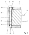
- a hub in the form of a bearing sleeve 21 is connected to the armature 7, at one end on its outer circumference by means of a bearing 18 in the housing 12 of the actuator 9 is pivotally mounted and has a central bore 29 in which a torsion bar spring 20 is accommodated is.
- This is in the area of the bearing 18 with one end 22 with the bearing sleeve 21 via a connecting piece 24 cohesively connected, first by friction welding on their front side, Capacitor discharge welding, diffusion welding or medium frequency pressure welding with the Connection piece 24 is welded, whereby a weld seam 26 is formed.
- the connecting piece 24 is made of a material which is connected to the torsion bar spring 20 both with the above-mentioned methods and with conventional ones Welding process can be welded to the bearing sleeve 21.
- the torsion bar 20 projects with her other end 23 out of the bearing sleeve 21 and engages in a bore 29 of the housing 12, with which it can be cohesively connected in the same way via a connecting piece 25.
- the Bearing sleeve 21 is at this end by means of a bearing 19 which is inserted into the central bore 29, pivotable on the torsion bar spring 20 or a housing connector surrounding the torsion bar spring 20 stored.
- Fig. 4 shows a variant in which a connecting layer 28 on the circumference of the torsion bar spring 20 End 22 is applied, which has the same properties as the connectors 24 and 25 respectively and thus e.g. can be connected to the bearing sleeve 21 by laser beam welding.
- Connection layer 28 can also occur a corresponding sleeve-shaped connecting piece that like the connecting piece 24, 25 is welded to the torsion bar spring 20.
Landscapes
- Engineering & Computer Science (AREA)
- General Engineering & Computer Science (AREA)
- Mechanical Engineering (AREA)
- Springs (AREA)
- Valve Device For Special Equipments (AREA)
Abstract
Description
- Fig. 1
- einen schematischen Teilschnitt durch einen Zylinderkopf einer Hubkolbenbrennkraftmaschine mit einem Aktuator,
- Fig. 2
- einen Schnitt entsprechend der Linie II-II in Fig. 1,
- Fig. 3
- einen vergrößerten Ausschnitt entsprechend der Linie III-III in Fig. 2 und
- Fig. 4
- eine Variante zu Fig. 3.
Claims (11)
- Drehstabfeder aus Federstahl mit einem hohen Kohlenstoffgehalt, die an ihren Enden mit jeweils einem Bauteil drehfest verbunden ist, wobei die Bauteile relativ zueinander schwenkbar gelagert sind, dadurch gekennzeichnet, dass die Drehstabfeder (20) durch Reibschweißen, Kondensatorentladungsschweißen, Diffusionsschweißen oder Mittelfrequenzpressschweißen über ein Verbindungsstück (24, 25) aus einem Werkstoff, der sich schmelzschweißen lässt, mit dem Bauteil (12, 21) verbunden ist, indem sie zuerst durch Reibschweißen, Kondensatorentladungsschweißen, Diffusionsschweißen oder Mittelfrequenzpressschweißen mit dem Verbindungsstück (24, 25) verschweißt wird und danach das Verbindungsstück (24, 25) durch Schmelzschweißen mit dem Bauteil (12, 21) verbunden wird.
- Drehstabfeder nach Anspruch 2, dadurch gekennzeichnet, dass als Schmelzschweißverfahren ein Laserstrahlschweißverfahren verwendet wird.
- Drehstabfeder nach einem der Ansprüche 2 bis 3, dadurch gekennzeichnet, dass das Verbindungsstück (24, 25) einen Kohlenstoffgehalt aufweist, der mit üblichen Schweißverfahren verschweißt werden kann.
- Drehstabfeder nach Anspruch 4, dadurch gekennzeichnet, dass das Verbindungsstück (24, 25) aus einem 16MnCr5-Stahl hergestellt ist.
- Drehstabfeder nach einem der Ansprüche 1 bis 5, dadurch gekennzeichnet, dass das Verbindungsstück (24, 25) mit einer Stimseite der Drehstabfeder (20) verschweißt ist.
- Drehstabfeder nach einem der Ansprüche 1 bis 5, dadurch gekennzeichnet, dass das Verbindungsstück (24, 25) am Umfang der Drehstabfeder (20) verschweißt ist.
- Drehstabfeder nach einem der Ansprüche 2 bis 7, dadurch gekennzeichnet, dass anstelle eines Verbindungsstücks (24, 25) eine Verbindungsschicht (28) auf der Drehstabfeder (20) aufgetragen ist.
- Drehstabfeder nach einem der Ansprüche 2 bis 8, dadurch gekennzeichnet, dass sie (20) nach dem Verschweißen mit dem Verbindungsstück (24, 25) bzw. dem Auftragen der Verbindungsschicht (28) vergütet und endbearbeitet wird.
- Drehstabfeder nach einem der Ansprüche 2 bis 9, dadurch gekennzeichnet, dass sie (20) in einer Bohrung (29) einer Nabe oder Lagerhülse (21) angeordnet ist, die Bestandteil eines Schwenklagers (8) eines Ankers (7) eines Aktuators (9) ist, der ein Gaswechselventil (4) einer Brennkraftmaschine betätigt.
- Drehstabfeder nach Anspruch 10, dadurch gekennzeichnet, dass die Nabe bzw. Lagerhülse (21) an einem Ende an ihrem äußeren Umfang mittels eines Lagers (18) in einem Gehäuse (12) schwenkbar gelagert und im Bereich des Lagers (18) in ihrer Bohrung (29) mit dem einen Ende (22) der Drehstabfeder (20) verbunden ist.
- Drehstabfeder nach Anspruch 11, dadurch gekennzeichnet, dass sie (20) mit ihrem anderen Ende (23) mit dem Gehäuse (12) verbunden ist und die Nabe bzw. die Lagerhülse (21) nahe dem Ende (23) auf der Drehstabfeder (20) mittels eines Lagers (19) in ihrer Bohrung (29) schwenkbar gelagert ist.
Applications Claiming Priority (2)
| Application Number | Priority Date | Filing Date | Title |
|---|---|---|---|
| DE10120399 | 2001-04-25 | ||
| DE10120399A DE10120399A1 (de) | 2001-04-25 | 2001-04-25 | Drehstabfeder |
Publications (2)
| Publication Number | Publication Date |
|---|---|
| EP1253343A2 true EP1253343A2 (de) | 2002-10-30 |
| EP1253343A3 EP1253343A3 (de) | 2004-01-14 |
Family
ID=7682760
Family Applications (1)
| Application Number | Title | Priority Date | Filing Date |
|---|---|---|---|
| EP02006350A Withdrawn EP1253343A3 (de) | 2001-04-25 | 2002-03-21 | Drehstabfeder |
Country Status (3)
| Country | Link |
|---|---|
| US (1) | US20030006542A1 (de) |
| EP (1) | EP1253343A3 (de) |
| DE (1) | DE10120399A1 (de) |
Families Citing this family (2)
| Publication number | Priority date | Publication date | Assignee | Title |
|---|---|---|---|---|
| DE10335791A1 (de) * | 2003-08-05 | 2005-03-10 | Innotec Forschungs & Entw Gmbh | Drehstabfeder |
| DE102017114171B4 (de) * | 2017-06-27 | 2019-05-29 | Schaeffler Technologies AG & Co. KG | Spindelelement eines Kugelgewindetriebs |
Citations (1)
| Publication number | Priority date | Publication date | Assignee | Title |
|---|---|---|---|---|
| DE3616540A1 (de) | 1986-05-16 | 1987-11-19 | Porsche Ag | Vorrichtung zum betaetigen eines gaswechsel-tellerventils einer hubkolben-brennkraftmaschine |
Family Cites Families (10)
| Publication number | Priority date | Publication date | Assignee | Title |
|---|---|---|---|---|
| FR1036573A (fr) * | 1949-10-28 | 1953-09-09 | Soupape de sûreté avec barre de torsion | |
| US3824368A (en) * | 1971-12-30 | 1974-07-16 | Avco Corp | Laser welding |
| GB1583317A (en) * | 1978-05-26 | 1981-01-21 | Rubery Owen Wrexham Ltd | Suspension units |
| DE3730334A1 (de) * | 1987-09-10 | 1989-03-23 | Daimler Benz Ag | Stabilisator fuer kraftfahrzeuge |
| US5026262A (en) * | 1989-11-28 | 1991-06-25 | Carrier Corporation | Multipiece eccentric shaft |
| JP3061505B2 (ja) * | 1993-04-05 | 2000-07-10 | 三菱製鋼株式会社 | トーションバー及びその製造方法 |
| DE19543603A1 (de) * | 1995-11-23 | 1997-05-28 | Schmitz & Brill Gmbh & Co Kg | Anordnung zur Schweißverbindung eines Grundelementes mit einem anderen Bauteil aus Stahl |
| SE506178C2 (sv) * | 1996-01-22 | 1997-11-17 | Sandvik Ab | Friktionssvetsad produkt för bergborrning samt förfarande för tillverkning av produkten |
| US6250334B1 (en) * | 1998-12-21 | 2001-06-26 | Ina Walzlager Schaeffler Ohg | Centering device for steering valves |
| US6336583B1 (en) * | 1999-03-23 | 2002-01-08 | Exxonmobil Upstream Research Company | Welding process and welded joints |
-
2001
- 2001-04-25 DE DE10120399A patent/DE10120399A1/de not_active Withdrawn
-
2002
- 2002-03-21 EP EP02006350A patent/EP1253343A3/de not_active Withdrawn
- 2002-04-24 US US10/128,585 patent/US20030006542A1/en not_active Abandoned
Patent Citations (1)
| Publication number | Priority date | Publication date | Assignee | Title |
|---|---|---|---|---|
| DE3616540A1 (de) | 1986-05-16 | 1987-11-19 | Porsche Ag | Vorrichtung zum betaetigen eines gaswechsel-tellerventils einer hubkolben-brennkraftmaschine |
Also Published As
| Publication number | Publication date |
|---|---|
| EP1253343A3 (de) | 2004-01-14 |
| DE10120399A1 (de) | 2002-10-31 |
| US20030006542A1 (en) | 2003-01-09 |
Similar Documents
| Publication | Publication Date | Title |
|---|---|---|
| DE69422277T2 (de) | Offendüsenkraftstoffeinspritzeinrichtung mit einem verschleissfesten Einspritzkolbenzusammenbau | |
| EP2636929B1 (de) | Verriegelungseinheit | |
| DE10155800A1 (de) | Schlepphebel eines Ventiltriebs einer Brennkraftmaschine | |
| DE10226821A1 (de) | Schlepphebel eines Ventiltriebs einer Brennkraftmaschine | |
| DE10155825A1 (de) | Schlepphebel eines Ventiltriebs einer Brennkraftmaschine | |
| DE10310220A1 (de) | Vorrichtung zur Koppelung bzw. Entkoppelung zweier Betätigungshebel eines Ventiltriebes einer Brennkraftmaschine und Verfahren hierzu | |
| EP4274956B1 (de) | Gasdosierventil zur dosierten abgabe von gasförmigem kraftstoff | |
| EP1974131B1 (de) | Gaswechselventilbetätigungsvorrichtung | |
| DE102011051268B4 (de) | Elektromagnetische Stellvorrichtung sowie Nockenwellenverstellvorrichtung | |
| EP3374625B1 (de) | Elektromagnetisch ansteuerbares saugventil für eine hochdruckpumpe, hochdruckpumpe | |
| DE10120399A1 (de) | Drehstabfeder | |
| DE19846354A1 (de) | Ventilsteuerzeiten-Verstellvorrichtung für eine Brennkraftmaschine | |
| DE19580325C1 (de) | Schlepphebel zur Betätigung eines Gaswechselventils | |
| DE10229912B4 (de) | Elektromagnetisches Hydraulikventil, insbesondere Proportionalventil zur Steuerung einer Vorrichtung zur Drehwinkelverstellung einer Nockenwelle gegenüber einer Kurbelwelle einer Brennkraftmaschine | |
| DE10048619A1 (de) | Abschaltbares Abstützelement | |
| EP1446562A1 (de) | Schlepphebel eines ventiltriebs einer brennkraftmaschine | |
| EP3312853A1 (de) | Elektromagnet | |
| DE10310219A1 (de) | Vorrichtung zur Koppelung bzw. Entkoppelung zweier Betätigungselemente eines Ventiltriebes einer Brennkraftmaschine und Verfahren hierzu | |
| DE102020105754B4 (de) | Kugelgewindetrieb | |
| DE697766C (de) | Einzelachsantrieb mit Federkupplung, insbesondere fuer elektrisch angetriebene Fahrzeuge | |
| DE10220788A1 (de) | Elektromagnetischer Aktuator mit einem Schwenkanker | |
| EP2643619A1 (de) | Ventileinrichtung mit einem wenigstens abschnittsweise zylindrischen bewegungselement | |
| EP1157226B1 (de) | Betätigungselement für ein zahnräderwechselgetriebe | |
| WO1999028601A1 (de) | Abschaltbarer kipp- oder schwinghebel | |
| DE4140073A1 (de) | Kreuzlenkergestaenge, insbesondere fuer eine wischeranlage eines fahrzeugs, und verfahren zu dessen herstellung |
Legal Events
| Date | Code | Title | Description |
|---|---|---|---|
| PUAI | Public reference made under article 153(3) epc to a published international application that has entered the european phase |
Free format text: ORIGINAL CODE: 0009012 |
|
| AK | Designated contracting states |
Kind code of ref document: A2 Designated state(s): AT BE CH CY DE DK ES FI FR GB GR IE IT LI LU MC NL PT SE TR |
|
| AX | Request for extension of the european patent |
Free format text: AL;LT;LV;MK;RO;SI |
|
| PUAL | Search report despatched |
Free format text: ORIGINAL CODE: 0009013 |
|
| AK | Designated contracting states |
Kind code of ref document: A3 Designated state(s): AT BE CH CY DE DK ES FI FR GB GR IE IT LI LU MC NL PT SE TR |
|
| AX | Request for extension of the european patent |
Extension state: AL LT LV MK RO SI |
|
| RIC1 | Information provided on ipc code assigned before grant |
Ipc: 7F 01L 9/04 B Ipc: 7F 16F 1/16 A |
|
| 17P | Request for examination filed |
Effective date: 20031217 |
|
| 17Q | First examination report despatched |
Effective date: 20040226 |
|
| AKX | Designation fees paid |
Designated state(s): DE FR GB IT |
|
| STAA | Information on the status of an ep patent application or granted ep patent |
Free format text: STATUS: THE APPLICATION HAS BEEN WITHDRAWN |
|
| 18W | Application withdrawn |
Effective date: 20060721 |