EP1253325A2 - Radial flow impeller - Google Patents
Radial flow impeller Download PDFInfo
- Publication number
- EP1253325A2 EP1253325A2 EP02253001A EP02253001A EP1253325A2 EP 1253325 A2 EP1253325 A2 EP 1253325A2 EP 02253001 A EP02253001 A EP 02253001A EP 02253001 A EP02253001 A EP 02253001A EP 1253325 A2 EP1253325 A2 EP 1253325A2
- Authority
- EP
- European Patent Office
- Prior art keywords
- impeller
- impeller blades
- predetermined
- point
- blades
- Prior art date
- Legal status (The legal status is an assumption and is not a legal conclusion. Google has not performed a legal analysis and makes no representation as to the accuracy of the status listed.)
- Granted
Links
Images


Classifications
-
- F—MECHANICAL ENGINEERING; LIGHTING; HEATING; WEAPONS; BLASTING
- F04—POSITIVE - DISPLACEMENT MACHINES FOR LIQUIDS; PUMPS FOR LIQUIDS OR ELASTIC FLUIDS
- F04D—NON-POSITIVE-DISPLACEMENT PUMPS
- F04D29/00—Details, component parts, or accessories
- F04D29/66—Combating cavitation, whirls, noise, vibration or the like; Balancing
- F04D29/661—Combating cavitation, whirls, noise, vibration or the like; Balancing especially adapted for elastic fluid pumps
- F04D29/666—Combating cavitation, whirls, noise, vibration or the like; Balancing especially adapted for elastic fluid pumps by means of rotor construction or layout, e.g. unequal distribution of blades or vanes
-
- E—FIXED CONSTRUCTIONS
- E01—CONSTRUCTION OF ROADS, RAILWAYS, OR BRIDGES
- E01H—STREET CLEANING; CLEANING OF PERMANENT WAYS; CLEANING BEACHES; DISPERSING OR PREVENTING FOG IN GENERAL CLEANING STREET OR RAILWAY FURNITURE OR TUNNEL WALLS
- E01H1/00—Removing undesirable matter from roads or like surfaces, with or without moistening of the surface
- E01H1/08—Pneumatically dislodging or taking-up undesirable matter or small objects; Drying by heat only or by streams of gas; Cleaning by projecting abrasive particles
- E01H1/0809—Loosening or dislodging by blowing ; Drying by means of gas streams
-
- F—MECHANICAL ENGINEERING; LIGHTING; HEATING; WEAPONS; BLASTING
- F04—POSITIVE - DISPLACEMENT MACHINES FOR LIQUIDS; PUMPS FOR LIQUIDS OR ELASTIC FLUIDS
- F04D—NON-POSITIVE-DISPLACEMENT PUMPS
- F04D29/00—Details, component parts, or accessories
- F04D29/26—Rotors specially for elastic fluids
- F04D29/28—Rotors specially for elastic fluids for centrifugal or helico-centrifugal pumps for radial-flow or helico-centrifugal pumps
- F04D29/281—Rotors specially for elastic fluids for centrifugal or helico-centrifugal pumps for radial-flow or helico-centrifugal pumps for fans or blowers
Definitions
- the present invention generally relates to radial flow fans and more particularly to a debris blower including a radial flow fan having an impeller with a noise reducing blade configuration.
- Debris blowers are known in which an impeller or a fan driven by a motor creates an air stream which is directed into a duct.
- the air stream discharged from the open end of the duct is employed to blow debris off walks, driveways and lawns.
- Known higher performance blowers employ a radial flow fan in order to efficiently generate the pressure and volumetric flow rate required for the application. These devices tend to be relatively noisy such that their use is often unpleasant for the user and those in the vicinity of the blower.
- Tonal emission at the blade passing frequency typically falls within the frequency range over which the human ear is sensitive and creates an unpleasant sound quality.
- the noise emission contains one or more discrete tones at frequencies related to the blade passing rate. It is this concentration of noise at one or more particular frequencies, rather than the overall amplitude of the noise, that most people find unpleasant.
- the present invention provides a radial flow fan having a housing having at least one inlet, an outlet and an impeller cavity in fluid connection with the inlet and the outlet, and an impeller.
- the impeller is rotatably supported in the impeller cavity on a rotary axis and includes an annular flange member and a plurality of impeller blades that are fixedly coupled to the annular flange member such that each of the impeller blades is adjacent another of the impeller blades in a predetermined circumferential direction.
- Each adjacent pair of the impeller blades defines a spacing angle.
- the impeller is configured such that a first predetermined quantity of the impeller blades are spaced apart from an associated adjacent impeller blade with a first predetermined spacing angle and a second predetermined quantity of the impeller blades are spaced apart from an associated adjacent impeller blade with a second predetermined spacing angle that is not equal to the first predetermined spacing angle.
- the plurality of first impeller blades are configured to intake a compressible fluid in a first direction generally parallel the rotary axis and to expel the compressible fluid to the outlet in a direction generally tangent the impeller cavity.
- the use of a plurality of spacing angles operates to distribute the noise that is generated by the rotating impeller blades over several tones or frequencies.
- a blower constructed in accordance with the teachings of the present invention is generally indicated by reference numeral 10.
- the blower 10 is shown to include a power source 12, a switch assembly 14 for selectively controlling the power source, a housing 16, an impeller 18 and a discharge tube assembly 20.
- the power source 12 is illustrated to include a motor assembly 30 having an electric motor 32 with a pair of terminals 34 and an output shaft 36.
- the motor assembly 30 and switch assembly 14 are conventional in their construction and operation and need not be discussed in significant detail.
- the switch assembly 14 is coupled to a source of electric power (e.g., via a power cord 40) and via the terminals 34, selectively provides the motor 32 with electricity in a predetermined manner that is related to the amount by which a trigger button 46 on the switch assembly 14 is depressed.
- a source of electric power e.g., via a power cord 40
- the terminals 34 selectively provides the motor 32 with electricity in a predetermined manner that is related to the amount by which a trigger button 46 on the switch assembly 14 is depressed.
- the housing 16 is illustrated to include a pair of housing shells 50 that collectively define a motor mounting portion 52, a switch mounting portion 54 and a volute 58 having an impeller cavity 60, a primary inlet 62, a secondary inlet 64 and an outlet 68.
- the motor and switch mounting portions 52 and 54 are conventional in their construction and operation, being employed to fixedly couple the motor assembly 30 and the switch assembly 14, respectively, within the housing 16.
- the motor assembly 30 is coupled to the housing 16 by the motor mounting portion 52, the distal end of the output shaft 36 extends rearwardly into the impeller cavity 60.
- the impeller cavity 60 extends radially around the output shaft 36 and is substantially enveloped on its forward and rearward sides by a pair of annular endwalls 70 and 72, respectively, into which the secondary and primary inlets 62 and 64, respectively, are formed.
- a plurality of vent apertures 76 that are skewed to the rotary axis 80 of the output shaft 36 are formed through the housing 16 forwardly of the endwall 70.
- a plurality of circumferentially extending inlet apertures 86 are spaced around the housing 16 rearwardly of the endwall 72. The circumference of the portion of the housing 16 into which the inlet apertures 86 are formed is illustrated to be larger than the diameter of the primary inlet 62.
- the outlet 68 intersects the impeller cavity 60 generally tangent to the outer diameter of the impeller cavity 60 in a manner that is conventionally known. However, the outlet 68 turns forwardly after this intersection and extends along an axis that is offset both vertically and horizontally from the rotary axis 80 of the output shaft 36.
- the outlet 68 terminates at a coupling portion 90 that is configured to releasably engage a mating coupling portion 92 on the proximal end 94 of the discharge tube assembly 20.
- the impeller 18 is illustrated to include a mounting hub 100, a flange member 102, a set of first impeller blades 104 and a set of second impeller blades 106.
- the mounting hub 100 is generally cylindrical and includes a mounting aperture 110, which is sized to engage the distal end of the output shaft 36 in a press-fit manner to thereby couple the impeller 18 to the motor assembly 30 for rotation about the rotary axis 80.
- the flange member 102 is coupled to the mounting hub 100 and extends radially outwardly therefrom in a continuous manner to thereby completely segregate the sets of first and second impeller blades 104 and 106 from one another.
- the impeller 18 rotates within the impeller cavity 60.
- Rotation of the set of first impeller blades 104 imparts momentum to the air that is disposed between each adjacent pair of first impeller blades 104, slinging the air radially outwardly toward the outlet 68.
- the air exiting the outlet 68 as a result of the momentum imparted by the set of first impeller blades 104 creates a negative pressure differential that generates a primary air flow 120 that enters the housing 16 through the inlet apertures 86 and is directed into the set of first impeller blades 104 by the primary inlet 62 in a direction generally parallel the rotary axis 80.
- rotation of the set of second impeller blades 106 imparts momentum to the air that is disposed between each adjacent pair of second impeller blades 106, slinging the air radially outwardly toward the outlet 68.
- the air exiting the outlet 68 as a result of the momentum imparted by the set of second impeller blades 106 creates a negative pressure differential that generates a secondary air flow 122 that enters the housing 16 through the vent apertures 76.
- the housing 16 is constructed such that the motor 32 rejects heat to the secondary air flow 122 before it travels through the secondary inlet 64.
- the secondary inlet 64 directs the secondary flow 122 into the set of second impeller blades 106 in a direction generally parallel the rotary axis 80 and opposite the primary air flow 120.
- the primary and secondary air flows 120 and 122 combine in the outlet 68 and are discharged through the coupling portion 90 into the discharge tube assembly 20.
- the height of the first impeller blades 104 is substantially larger than that of the second impeller blades 106 and as such, the mass flow rate of the primary air flow 120 will be substantially larger than the mass flow rate of the secondary air flow 122.
- the primary and secondary flows 120 and 122 cannot travel in an axial direction beyond the flange member 102 until they have been slung radially outwardly of the impeller 18.
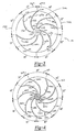
- the set of first impeller blades 104 is fixedly coupled to a first side 150 of the flange member 102 such that each pair of the first impeller blades 104 (e.g., first impeller blades 104a and 104b) is separated by a predetermined spacing angle 152, wherein one of the pair of first impeller blades 104 (e.g., first impeller blade 104b) is spaced apart from the other one of the pair of first impeller blades 104 (e.g., first impeller blade 104a) in a predetermined circumferential direction by the spacing angle 152.
- the set of first impeller blades 104 are spaced about the flange member 102 such that spacing angles 152 having at least two different magnitudes are employed to space the first impeller blades 104 apart.
- the set of first impeller blades 104 are spaced apart with a spacing angles 152 having a multiplicity of magnitudes, wherein the spacing angles 152 are distributed in a predetermined pattern that is repeated around the circumference of the impeller 18.
- the set of second impeller blades 106 is fixedly coupled to a second side 160 of the flange member 102 such that each pair of the second impeller blades 106 (e.g., second impeller blades 106a and 106b) is separated by a predetermined spacing angle 162, wherein one of the pair of second impeller blades 106 (e.g., second impeller blade 106b) is spaced apart from the other one of the pair of second impeller blades 106 (e.g., second impeller blade 106a) in a predetermined circumferential direction by the spacing angle 162.
- the set of second impeller blades 106 are also spaced about the flange member 102 such that spacing angles 162 having at least two different magnitudes are employed to space the second impeller blades 106 apart.
- the set of second impeller blades 106 are preferably spaced apart with spacing angles 162 having a multiplicity of magnitudes, wherein the spacing angles 162 are distributed in a predetermined pattern that is repeated around the circumference of the impeller 18.
- the magnitudes and pattern of spacing angles 162 for the set of second impeller blades 106 is different from the magnitudes and pattern of the spacing angles 152 for the set of first impeller blades 104.
- the pattern of spacing angles 152 that is employed for the set of first impeller blades 104 is configured such that a first one of the first impeller blades 104 (e.g., first impeller blade 104b) is adjacent a first one of the other first impeller blades (e.g., first impeller blade 104a) and cooperates to define a first area 170 on the flange member 102 therebetween, and each of the first impeller blades 104 (e.g., first impeller blade 104b) is also adjacent a second one of the other first impeller blades (e.g., first impeller blade 104c) and cooperates to define a second area 172 on the flange member 102 therebetween.
- the spacing of the first impeller blades 104 is such that none of the first and second areas 170 and 172 that are adjacent any one of the first impeller blades 104 is equal in magnitude.
- Each of the first impeller blades 104 is shown to begin at an inward point 174 and terminate at an outward point 176.
- Each of the first impeller blades 104 (e.g., first impeller blade 104b) is configured such that its inward point 174 is radially inward of the outward point 176 of the first one of the other first impeller blades 104 (e.g., first impeller blade 104a) and its outward point 176 is radially outward of the inward point 174 of the second one of the other first impeller blades 104 (e.g., first impeller blade 104c).
- a first straight line passes through the mounting aperture 110 through the inward point 174 of the first impeller blade 104b and the outward point 176 of the first impeller blade 104a and a second straight line passes through the mounting aperture 110 through the inward point 174 of the first impeller blade 104c and the outward point 176 of the first impeller blade 104b.
- Each first impeller blade 104 is arcuately shaped from its inward point 174 to its outward point 176.
- Each first impeller blade 104 tapers outwardly away from the flange member 102 from its inward point 174 to an intermediate point 178 between the inward and outward points 174 and 176.
- the pattern of spacing angles 162 that is employed for the set of second impeller blades 106 is configured such that each of the second impeller blades 106 (e.g., second impeller blade 106b) is adjacent a first one of the other second impeller blades (e.g., second impeller blade 106a) and cooperates to define a third area 180 on the flange member 102 therebetween, and each of the second impeller blades 106 (e.g., second impeller blade 106b) is also adjacent a second one of the other second impeller blades (e.g., second impeller blade 106c) and cooperates to define a fourth area 182 on the flange member 102 therebetween.
- the spacing of the second impeller blades 106 is such that none of the third and fourth areas 180 and 182 that are adjacent any one of the second impeller blades 106 is equal in magnitude.
- Each of the second impeller blades 106 begins at an inward point 184 and terminates at an outward point 186.
- Each of the second impeller blades 106 (e.g., second impeller blade 106b) is configured such that its outward point 186 is radially outward of the inward point 184 of the first one of the other second impeller blades 106 (e.g., second impeller blade 106a) and its inward point 184 is radially inward of the outward point 186 of the second one of the other second impeller blades 106 (e.g., second impeller blade 106c).
- Each second impeller blade 106 is arcuately shaped from its inward point 184 to its outward point 186.
- a first straight line passes through the mounting aperture 110 through the inward point 184 of the first impeller blade 106b and the outward point 186 of the first impeller blade 106c and a second straight line passes through the mounting aperture 110 through the inward point 184 of the first impeller blade 106a and the outward point 186 of the first impeller blade 106b.
- Each second impeller blade 106 tapers outwardly away from the flange member 102 from its inward point 184 to an intermediate point 188 between the inward and outward points 184 and 186.
- the spacing between any adjacent pair of impeller blades is not equal to any other spacing between an adjacent pair of any of the other first and second impeller blades 104 and 106 to thereby distribute the noise energy over a maximum number of frequencies.
- Construction in this manner is extremely difficult, particularly where the impeller 18 is formed in a molding process, due to the unsymmetrical distribution of material in the impeller 18.
- the unsymmetrical distribution of material tends to facilitate distortion in the molded impeller 18 as it cools, as well as offsets its rotational center of gravity about its axis of rotation so that it vibrates when it is rotated.
- the set of first impeller blades 104 are instead divided into a plurality of identically configured first blade groups 200, wherein each of the first blade groups 200 includes an identical quantity of the first impeller blades 104 which are spaced apart in a predetermined first blade spacing pattern.
- each of the first blade groups 200 includes a total of four (4) of the first impeller blades 104a, 104b, 104c and 104d, with the first impeller blade 104a being spaced apart from predetermined reference point (e.g.
- the first blade groups 200 are fixed to the first side 150 of the flange member 102 such that they are offset from one another by a predetermined angular spacing (e.g., 57°).
- each of the second blade groups 220 includes an identical quantity of the second impeller blades 106 which are spaced apart in a predetermined second blade spacing pattern.
- each of the second blade groups 220 includes a total of three (3) of the second impeller blades 106a, 106b and 106c, with the second impeller blade 106a being spaced apart from predetermined reference point (e.g.
- the second blade groups 220 are fixed to the second side 170 of the flange member 102 such that they are offset from one another by a predetermined angular spacing (e.g., 40°).
- noise attenuation is primarily achieved through the configuration of the impeller 18, the geometry of the housing 16 is also employed to aid in the attenuation of the noise that is generated during the operation of the blower 10.
- noise that results from the rotation of the impeller 18 is not discharged in a direct or straight-line manner from the housing 16 but rather is reflected off several various interior surfaces within the housing 16 as shown in Figure 2.
- noise 250 that is directed rearwardly from the impeller 18 is reflected off the rearward wall 252 before it is reflected outwardly through the inlet apertures 86.
- noise 250 that is directed forwardly from the impeller 18 is reflected off the walls 254 of the outlet 68 before it is discharged through the outlet 68.
- the reflecting of noise 250 off the various interior surfaces of the housing 16 permits the housing 16 to absorb some of the energy of the noise 250 to thereby attenuate the level of noise 250 that is transmitted out of the housing 16.
Landscapes
- Engineering & Computer Science (AREA)
- Mechanical Engineering (AREA)
- General Engineering & Computer Science (AREA)
- Architecture (AREA)
- Civil Engineering (AREA)
- Structural Engineering (AREA)
- Structures Of Non-Positive Displacement Pumps (AREA)
- Massaging Devices (AREA)
- Toys (AREA)
Abstract
Description
Claims (34)
- A portable debris blower comprising:wherein the plurality of first impeller blades are configured to intake a compressible fluid in a first direction generally parallel the rotary axis and expel the compressible fluid to the outlet in a direction generally tangent the impeller cavity.a housing having at least one inlet, an outlet and an impeller cavity;a power source coupled to the cavity and having an output shaft for providing a rotational output;an impeller disposed within the impeller cavity and coupled for rotation with the output shaft, the impeller including an annular flange member and a plurality of impeller blades fixedly coupled to the annular flange member such that each of the impeller blades is adjacent another of the impeller blades in a predetermined circumferential direction, each adjacent pair of impeller blades defining a spacing angle, the impeller being configured such that a first predetermined quantity of the impeller blades are spaced apart from an associated adjacent impeller blade with a first predetermined spacing angle and a second predetermined quantity of the impeller blades are spaced apart from an associated adjacent impeller blade with a second predetermined spacing angle that is not equal to the first predetermined spacing angle, the plurality of impeller blades being segregated into a plurality of identically configured blade groups, each of the blade groups having an equal number of impeller blades, the impeller blades within one of the blade groups being spaced apart from one another with a predetermined pattern of spacing angles including at least one of the first predetermined spacing angle and the second predetermined spacing angle;
- The portable debris blower of Claim 1, wherein a spacing angle between a last impeller blades in a first one of the impeller blade groups and a first one of the impeller blades in a next one of the impeller blade groups is not equal to a spacing angle between each adjacent pair of impeller blades in the first one of the impeller blade groups.
- The portable debris blower of Claim 2, wherein the predetermined pattern of spacing angles includes a plurality of non-equal spacing angles.
- The portable debris blower of Claim 3, wherein the predetermined pattern of spacing angles includes a plurality of non-equal spacing angles.
- The portable debris blower of Claim 1, further comprising a plurality of second impeller blades, the second impeller blades being fixedly coupled to the annular flange member such that each of the second impeller blades is adjacent another of the second impeller blades in a predetermined circumferential direction, each adjacent pair of second impeller blades defining a second spacing angle, the impeller being configured such that a first predetermined quantity of the second impeller blades are spaced apart from an associated adjacent second impeller blade with a third predetermined spacing angle and a second predetermined quantity of the second impeller blades are spaced apart from an associated adjacent second impeller blade with a fourth predetermined spacing angle that is not equal to the third predetermined spacing angle;
wherein the plurality of second impeller blades are configured to intake a compressible fluid in a second direction generally parallel the rotary axis and expel the compressible fluid to the outlet in a direction generally tangent the impeller cavity. - The portable debris blower of Claim 5, wherein the plurality of second impeller blades are segregated into a plurality of identically configured second blade groups, each of the second blade groups having an equal number of the second impeller blades, the second impeller blades within one of the second blade groups being spaced apart from one another with a predetermined second pattern of spacing angles including at least one of the third predetermined spacing angle and the fourth predetermined spacing angle.
- The portable debris blower of Claim 6, wherein a spacing angle between a last impeller blades in a first one of the second impeller blade groups and a first one of the impeller blades in a next one of the second impeller blade groups is not equal to a spacing angle between each adjacent pair of the second impeller blades in the first one of the second impeller blade groups.
- The portable debris blower of Claim 7, wherein the predetermined pattern of spacing angles includes a plurality of non-equal spacing angles.
- The portable debris blower of Claim 6, wherein the predetermined pattern of spacing angles includes a plurality of non-equal spacing angles.
- The portable debris blower of Claim 6, wherein each of the second impeller blades begins at an inward point and terminates at an outward point, each of the second impeller blades being configured such that its inward point is radially inward of the outward point of the first one of the other second impeller blades and its outward point is radially outward of the inward point of the second one of the other second impeller blades.
- The portable debris blower of Claim 10, wherein each of the second impeller blades is arcuately shaped from the inward point to the outward point.
- The portable debris blower of Claim 10, wherein each of the second impeller blades tapers outwardly away from the flange member from the inward point to an intermediate point between the inward and outward points.
- The portable debris blower of Claim 6, wherein the predetermined number of first blade groups is not equal to the predetermined number of second blade groups.
- The portable debris blower of Claim 13, wherein a quantity of the first impeller blades that form one of the first blade groups is not equal to a quantity of the second impeller blades that form one of the second blade groups.
- The portable debris blower of Claim 1, wherein each of the impeller blades begins at an inward point and terminates at an outward point, each of the impeller blades being configured such that its inward point is radially inward of the outward point of the first one of the other impeller blades and its outward point is radially outward of the inward point of the second one of the other impeller blades.
- The portable debris blower of Claim 15, wherein each of the impeller blades is arcuately shaped from the inward point to the outward point.
- The portable debris blower of Claim 15, wherein each of the impeller blades tapers outwardly away from the flange member from the inward point to an intermediate point between the inward and outward points.
- A radial flow fan comprising:wherein the plurality of impeller blades are configured to intake a compressible fluid in a first direction generally parallel the rotary axis and expel the compressible fluid to the outlet in a direction generally tangent the impeller cavity.a housing having at least one inlet, an outlet and an impeller cavity in fluid connection with the inlet and the outlet; andan impeller rotatably supported in the impeller cavity on a rotary axis, the impeller having an annular flange member and a plurality of impeller blades fixedly coupled to the annular flange member such that each of the impeller blades is adjacent another of the impeller blades in a predetermined circumferential direction, each adjacent pair of impeller blades defining a spacing angle, the impeller being configured such that a first predetermined quantity of the impeller blades are spaced apart from an associated adjacent impeller blade with a first predetermined spacing angle and a second predetermined quantity of the impeller blades are spaced apart from an associated adjacent impeller blade with a second predetermined spacing angle that is not equal to the first predetermined spacing angle, the plurality of impeller blades being segregated into a plurality of identically configured first blade groups, each of the first blade groups having an equal number of impeller blades, the impeller blades within one of the first blade groups being spaced apart from one another with a predetermined pattern of spacing angles including at least one of the first predetermined spacing angle and the second predetermined spacing angle;
- The radial flow fan of Claim 1, wherein a spacing angle between a last impeller blades in a first one of the impeller blade groups and a first one of the impeller blades in a next one of the impeller blade groups is not equal to a spacing angle between each adjacent pair of impeller blades in the first one of the impeller blade groups.
- The radial flow fan of Claim 2, wherein the predetermined pattern of spacing angles includes a plurality of non-equal spacing angles.
- The radial flow fan of Claim 1, wherein the predetermined pattern of spacing angles includes a plurality of non-equal spacing angles.
- The radial flow fan of Claim 1, further comprising a plurality of second impeller blades, the second impeller blades being fixedly coupled to the annular flange member such that each of the second impeller blades is adjacent another of the second impeller blades in a predetermined circumferential direction, each adjacent pair of second impeller blades defining a second spacing angle, the impeller being configured such that a first predetermined quantity of the second impeller blades are spaced apart from an associated adjacent second impeller blade with a third predetermined spacing angle and a second predetermined quantity of the second impeller blades are spaced apart from an associated adjacent second impeller blade with a fourth predetermined spacing angle that is not equal to the third predetermined spacing angle;
wherein the plurality of second impeller blades are configured to intake a compressible fluid in a second direction generally parallel the rotary axis and expel the compressible fluid to the outlet in a direction generally tangent the impeller cavity. - The radial flow fan of Claim 5, wherein the plurality of second impeller blades are segregated into a plurality of identically configured second blade groups, each of the second blade groups having an equal number of the second impeller blades, the second impeller blades within one of the second blade groups being spaced apart from one another with a predetermined second pattern of spacing angles including at least one of the third predetermined spacing angle and the fourth predetermined spacing angle.
- The radial flow fan of Claim 6, wherein a spacing angle between a last impeller blades in a first one of the second impeller blade groups and a first one of the impeller blades in a next one of the second impeller blade groups is not equal to a spacing angle between each adjacent pair of the second impeller blades in the first one of the second impeller blade groups.
- The radial flow fan of Claim 7, wherein the predetermined second pattern of spacing angles includes a plurality of non-equal spacing angles.
- The radial flow fan of Claim 6, wherein the predetermined second pattern of spacing angles includes a plurality of non-equal spacing angles.
- The radial flow fan of Claim 6, wherein each of the second impeller blades begins at an inward point and terminates at an outward point, each of the second impeller blades being configured such that its inward point is radially inward of the outward point of the first one of the other second impeller blades and its outward point is radially outward of the inward point of the second one of the other second impeller blades.
- The radial flow fan of Claim 10, wherein each of the second impeller blades is arcuately shaped from the inward point to the outward point.
- The radial flow fan of Claim 10, wherein each of the second impeller blades tapers outwardly away from the flange member from the inward point to an intermediate point between the inward and outward points.
- The radial flow fan of Claim 6, wherein the predetermined number of first blade groups is not equal to the predetermined number of second blade groups.
- The radial flow fan of Claim 6, wherein a quantity of the first impeller blades that form one of the first blade groups is not equal to a quantity of the second impeller blades that form one of the second blade groups.
- The radial flow fan of Claim 1, wherein each of the impeller blades begins at an inward point and terminates at an outward point, each of the impeller blades being configured such that its inward point is radially inward of the outward point of the first one of the other impeller blades and its outward point is radially outward of the inward point of the second one of the other impeller blades.
- The radial flow fan of Claim 15, wherein each of the impeller blades is arcuately shaped from the inward point to the outward point.
- The radial flow fan of Claim 15, wherein each of the impeller blades tapers outwardly away from the flange member from the inward point to an intermediate point between the inward and outward points.
Priority Applications (1)
| Application Number | Priority Date | Filing Date | Title |
|---|---|---|---|
| EP06110550.8A EP1662148A3 (en) | 2001-04-27 | 2002-04-26 | Radial flow impeller |
Applications Claiming Priority (2)
| Application Number | Priority Date | Filing Date | Title |
|---|---|---|---|
| US09/845,061 US6514036B2 (en) | 2001-04-27 | 2001-04-27 | Radial flow fan with impeller having blade configuration for noise reduction |
| US845061 | 2001-04-27 |
Related Child Applications (1)
| Application Number | Title | Priority Date | Filing Date |
|---|---|---|---|
| EP06110550.8A Division EP1662148A3 (en) | 2001-04-27 | 2002-04-26 | Radial flow impeller |
Publications (3)
| Publication Number | Publication Date |
|---|---|
| EP1253325A2 true EP1253325A2 (en) | 2002-10-30 |
| EP1253325A3 EP1253325A3 (en) | 2003-10-29 |
| EP1253325B1 EP1253325B1 (en) | 2006-06-21 |
Family
ID=25294296
Family Applications (2)
| Application Number | Title | Priority Date | Filing Date |
|---|---|---|---|
| EP02253001A Expired - Lifetime EP1253325B1 (en) | 2001-04-27 | 2002-04-26 | Radial flow impeller |
| EP06110550.8A Withdrawn EP1662148A3 (en) | 2001-04-27 | 2002-04-26 | Radial flow impeller |
Family Applications After (1)
| Application Number | Title | Priority Date | Filing Date |
|---|---|---|---|
| EP06110550.8A Withdrawn EP1662148A3 (en) | 2001-04-27 | 2002-04-26 | Radial flow impeller |
Country Status (6)
| Country | Link |
|---|---|
| US (1) | US6514036B2 (en) |
| EP (2) | EP1253325B1 (en) |
| AT (1) | ATE331142T1 (en) |
| AU (1) | AU784627B2 (en) |
| DE (1) | DE60212495T2 (en) |
| ES (1) | ES2266411T3 (en) |
Cited By (7)
| Publication number | Priority date | Publication date | Assignee | Title |
|---|---|---|---|---|
| EP1872646A1 (en) * | 2006-06-30 | 2008-01-02 | CNH Belgium N.V. | Rotating inlet for cross flow fan. |
| GB2478646A (en) * | 2010-03-09 | 2011-09-14 | Bosch Gmbh Robert | Fan blade spacing and/or construction |
| CN104047250A (en) * | 2014-05-22 | 2014-09-17 | 浙江大学 | Dust collector |
| CN104132004A (en) * | 2014-08-04 | 2014-11-05 | 绿田机械股份有限公司 | Cooling fan used for diesel engine |
| EP3623637A1 (en) * | 2018-09-14 | 2020-03-18 | Yen Sun Technology Corp. | Centrifugal fan |
| DE102008010912B4 (en) * | 2007-02-23 | 2020-11-12 | Sew-Eurodrive Gmbh & Co Kg | Fan wheel, system and gear series |
| CN112483444A (en) * | 2020-11-26 | 2021-03-12 | 宁波奥晟机械有限公司 | Garden blower |
Families Citing this family (38)
| Publication number | Priority date | Publication date | Assignee | Title |
|---|---|---|---|---|
| US6629818B2 (en) * | 2001-02-09 | 2003-10-07 | The Toro Company | Impeller for use with portable blower/vacuums |
| US7201563B2 (en) * | 2004-09-27 | 2007-04-10 | Studebaker Enterprises, Inc. | Louvered fan grille for a shrouded floor drying fan |
| TW200722627A (en) * | 2005-12-15 | 2007-06-16 | Ind Tech Res Inst | Centrifugal type pressure-increasing impeller structure |
| CN1987117B (en) * | 2005-12-23 | 2010-04-07 | 财团法人工业技术研究院 | Centrifugal type pressurization impeller structure |
| US20080152487A1 (en) * | 2006-12-22 | 2008-06-26 | Shaffer Chadwick A | Portable blower/vacuum and impeller for use with same |
| TWI326333B (en) * | 2006-12-26 | 2010-06-21 | Sunonwealth Electr Mach Ind Co | Low air-noise fan housing structure |
| US8814522B2 (en) * | 2007-06-15 | 2014-08-26 | Cymer, Llc | Cross-flow fan impeller for a transversley excited, pulsed, gas discharge laser |
| JP4981535B2 (en) * | 2007-06-20 | 2012-07-25 | 株式会社ケーヒン | Centrifugal blower |
| TWM418176U (en) * | 2011-04-01 | 2011-12-11 | Delta Electronics Inc | Impeller |
| DE112012003045B4 (en) * | 2011-07-07 | 2024-01-04 | Makita Corporation | power tool |
| CA2840594C (en) | 2011-07-13 | 2020-03-10 | Fisher & Paykel Healthcare Limited | Impeller and motor assembly |
| US10137264B2 (en) | 2011-07-13 | 2018-11-27 | Fisher & Paykel Healthcare Limited | Respiratory assistance apparatus |
| AU2013101734A4 (en) | 2012-12-18 | 2015-09-24 | Fisher & Paykel Healthcare Limited | Impeller and motor assembly |
| GB2524315B (en) * | 2014-03-20 | 2017-10-11 | Johnston Sweepers Ltd | A road cleaning vehicle comprising a debris collection arrangement |
| WO2015161883A1 (en) * | 2014-04-24 | 2015-10-29 | Husqvarna Ab | Noise reduction system for a blower |
| CN106457964B (en) * | 2014-06-11 | 2019-04-02 | 松下知识产权经营株式会社 | Thermoregulation unit, thermoregulation system and vehicle with thermoregulation unit |
| JP2016112523A (en) * | 2014-12-16 | 2016-06-23 | 株式会社マキタ | Blower working machine |
| DE102015212203A1 (en) * | 2015-06-30 | 2017-01-05 | Ksb Aktiengesellschaft | Vortex pump |
| CN206617363U (en) * | 2017-03-01 | 2017-11-07 | 讯凯国际股份有限公司 | impeller |
| US11401974B2 (en) | 2017-04-23 | 2022-08-02 | Fisher & Paykel Healthcare Limited | Breathing assistance apparatus |
| US10648486B2 (en) | 2017-05-08 | 2020-05-12 | Microsoft Technology Licensing, Llc | Fan with impeller based on an audio spread-spectrum |
| CN107288924A (en) * | 2017-08-17 | 2017-10-24 | 联想(北京)有限公司 | A kind of electronic equipment and its radiator fan |
| CN108167222B (en) * | 2017-12-06 | 2019-10-22 | 九阳股份有限公司 | A kind of cooking apparatus quiet fan |
| WO2020031082A1 (en) * | 2018-08-08 | 2020-02-13 | Fpz S.P.A. | Blade rotor and fluid working machine comprising such rotor |
| AU2020205211B2 (en) | 2019-08-02 | 2026-01-15 | Techtronic Cordless Gp | Blowers having noise reduction features |
| AU2020286200A1 (en) | 2020-01-21 | 2021-08-05 | Techtronic Cordless Gp | Power tool having noise reduction features |
| CN214742186U (en) | 2020-01-21 | 2021-11-16 | 创科无线普通合伙 | Blower fan |
| KR102818559B1 (en) * | 2020-01-31 | 2025-06-10 | 엘지전자 주식회사 | Pump |
| USD1077859S1 (en) | 2020-11-17 | 2025-06-03 | Milwaukee Electric Tool Corporation | Blower |
| US11889794B2 (en) | 2020-12-30 | 2024-02-06 | Milwaukee Electric Tool Corporation | Handheld blower |
| DE112022003963T5 (en) * | 2021-10-11 | 2024-07-04 | Milwaukee Electric Tool Corporation | BLOWER FOR A HANDHELD BLOWER |
| EP4202126A1 (en) * | 2021-12-21 | 2023-06-28 | Andreas Stihl AG & Co. KG | Electric blowing device with a rechargeable battery pack |
| EP4202229A1 (en) * | 2021-12-21 | 2023-06-28 | Andreas Stihl AG & Co. KG | Cooling air guide on an electric blower |
| EP4201198A1 (en) * | 2021-12-21 | 2023-06-28 | Andreas Stihl AG & Co. KG | Electric blowing device with a sound cover |
| JP7752061B2 (en) * | 2022-01-27 | 2025-10-09 | 株式会社やまびこ | Blower |
| CN116658456A (en) * | 2022-02-18 | 2023-08-29 | 全亿大科技(佛山)有限公司 | Fan and electronic device |
| US12352274B2 (en) | 2022-03-21 | 2025-07-08 | Milwaukee Electric Tool Corporation | Axial blower |
| CN221547328U (en) * | 2023-12-01 | 2024-08-16 | 石开慧 | Hair drier |
Family Cites Families (11)
| Publication number | Priority date | Publication date | Assignee | Title |
|---|---|---|---|---|
| DE165330C (en) * | ||||
| DE1291851B (en) * | 1960-05-31 | 1969-04-03 | Siemens Ag | Device for noise reduction on multi-blade radial fans for ventilation of electrical machines |
| GB1293553A (en) * | 1969-02-18 | 1972-10-18 | Cav Ltd | Radial flow fans |
| US3601876A (en) | 1969-03-17 | 1971-08-31 | Gen Motors Corp | Method of manufacturing a one-piece fan |
| US4187055A (en) | 1978-04-03 | 1980-02-05 | Vernco Corporation | Flexible fan |
| GB2046360A (en) * | 1979-03-31 | 1980-11-12 | Aes Plastics Ltd | Fluid impeller |
| US4870714A (en) * | 1987-11-09 | 1989-10-03 | Black & Decker Inc. | Portable blower/vacuum system |
| US6158954A (en) * | 1998-03-30 | 2000-12-12 | Sanyo Electric Co., Ltd. | Cross-flow fan and an air-conditioner using it |
| KR20000032976A (en) * | 1998-11-18 | 2000-06-15 | 윤종용 | Cross flow fan for air conditioner |
| US6105206A (en) | 1999-04-13 | 2000-08-22 | Department Of Water And Power City Of Los Angeles | Portable electrically powered blower apparatus |
| KR100315518B1 (en) * | 1999-09-10 | 2001-11-30 | 윤종용 | Crossflow fan for an air conditioner |
-
2001
- 2001-04-27 US US09/845,061 patent/US6514036B2/en not_active Expired - Fee Related
-
2002
- 2002-04-26 AU AU37040/02A patent/AU784627B2/en not_active Ceased
- 2002-04-26 DE DE60212495T patent/DE60212495T2/en not_active Expired - Lifetime
- 2002-04-26 ES ES02253001T patent/ES2266411T3/en not_active Expired - Lifetime
- 2002-04-26 AT AT02253001T patent/ATE331142T1/en not_active IP Right Cessation
- 2002-04-26 EP EP02253001A patent/EP1253325B1/en not_active Expired - Lifetime
- 2002-04-26 EP EP06110550.8A patent/EP1662148A3/en not_active Withdrawn
Cited By (8)
| Publication number | Priority date | Publication date | Assignee | Title |
|---|---|---|---|---|
| EP1872646A1 (en) * | 2006-06-30 | 2008-01-02 | CNH Belgium N.V. | Rotating inlet for cross flow fan. |
| DE102008010912B4 (en) * | 2007-02-23 | 2020-11-12 | Sew-Eurodrive Gmbh & Co Kg | Fan wheel, system and gear series |
| GB2478646A (en) * | 2010-03-09 | 2011-09-14 | Bosch Gmbh Robert | Fan blade spacing and/or construction |
| CN104047250A (en) * | 2014-05-22 | 2014-09-17 | 浙江大学 | Dust collector |
| CN104047250B (en) * | 2014-05-22 | 2015-11-18 | 浙江大学 | Dust arrester |
| CN104132004A (en) * | 2014-08-04 | 2014-11-05 | 绿田机械股份有限公司 | Cooling fan used for diesel engine |
| EP3623637A1 (en) * | 2018-09-14 | 2020-03-18 | Yen Sun Technology Corp. | Centrifugal fan |
| CN112483444A (en) * | 2020-11-26 | 2021-03-12 | 宁波奥晟机械有限公司 | Garden blower |
Also Published As
| Publication number | Publication date |
|---|---|
| AU784627B2 (en) | 2006-05-18 |
| US6514036B2 (en) | 2003-02-04 |
| EP1253325A3 (en) | 2003-10-29 |
| AU3704002A (en) | 2002-10-31 |
| DE60212495D1 (en) | 2006-08-03 |
| US20020159881A1 (en) | 2002-10-31 |
| DE60212495T2 (en) | 2007-06-14 |
| ES2266411T3 (en) | 2007-03-01 |
| EP1662148A2 (en) | 2006-05-31 |
| ATE331142T1 (en) | 2006-07-15 |
| EP1662148A3 (en) | 2013-07-17 |
| EP1253325B1 (en) | 2006-06-21 |
Similar Documents
| Publication | Publication Date | Title |
|---|---|---|
| US6514036B2 (en) | Radial flow fan with impeller having blade configuration for noise reduction | |
| US10935039B2 (en) | Blower impeller for a handheld blower | |
| EP3225742B1 (en) | Air blower and blower/vacuum apparatus | |
| CN220452243U (en) | Handheld fan | |
| CN102088884B (en) | Mufflers for drying equipment and quiet blowers | |
| US6105206A (en) | Portable electrically powered blower apparatus | |
| CA2960405C (en) | Axial fan blower | |
| US5988979A (en) | Centrifugal blower wheel with an upwardly extending, smoothly contoured hub | |
| US6591516B2 (en) | Hair dryer | |
| US4448573A (en) | Single-stage, multiple outlet centrifugal blower | |
| EP0837245A2 (en) | Fan for air handling system | |
| CN113431796B (en) | Knapsack type blower | |
| JP7672291B2 (en) | Axial Flow Blower | |
| EP0651161B1 (en) | Device for cooling en electric motor for a turbo-fan | |
| CN110630540A (en) | Electric blower and electric vacuum cleaner | |
| KR970000161A (en) | cleaner | |
| WO2019223438A1 (en) | Air blower | |
| KR970020018A (en) | Vacuum cleaner | |
| MA26113A1 (en) | AIR EXHAUST FAN | |
| US20240280110A1 (en) | Fan for handheld blower | |
| CN110528434A (en) | hair dryer | |
| JP4448929B2 (en) | Portable blower | |
| JPH07224788A (en) | Sirocco fan | |
| JP7520388B2 (en) | Blower fan | |
| KR100741789B1 (en) | Exhaust hood and his centrifugal fan |
Legal Events
| Date | Code | Title | Description |
|---|---|---|---|
| PUAI | Public reference made under article 153(3) epc to a published international application that has entered the european phase |
Free format text: ORIGINAL CODE: 0009012 |
|
| AK | Designated contracting states |
Kind code of ref document: A2 Designated state(s): AT BE CH CY DE DK ES FI FR GB GR IE IT LI LU MC NL PT SE TR |
|
| AX | Request for extension of the european patent |
Free format text: AL;LT;LV;MK;RO;SI |
|
| PUAL | Search report despatched |
Free format text: ORIGINAL CODE: 0009013 |
|
| AK | Designated contracting states |
Kind code of ref document: A3 Designated state(s): AT BE CH CY DE DK ES FI FR GB GR IE IT LI LU MC NL PT SE TR |
|
| AX | Request for extension of the european patent |
Extension state: AL LT LV MK RO SI |
|
| RIC1 | Information provided on ipc code assigned before grant |
Ipc: 7F 04D 29/28 A Ipc: 7E 01H 1/08 B Ipc: 7F 04D 29/66 B |
|
| 17P | Request for examination filed |
Effective date: 20031204 |
|
| AKX | Designation fees paid |
Designated state(s): AT BE CH CY DE DK ES FI FR GB GR IE IT LI LU MC NL PT SE TR |
|
| GRAP | Despatch of communication of intention to grant a patent |
Free format text: ORIGINAL CODE: EPIDOSNIGR1 |
|
| GRAS | Grant fee paid |
Free format text: ORIGINAL CODE: EPIDOSNIGR3 |
|
| GRAA | (expected) grant |
Free format text: ORIGINAL CODE: 0009210 |
|
| AK | Designated contracting states |
Kind code of ref document: B1 Designated state(s): AT BE CH CY DE DK ES FI FR GB GR IE IT LI LU MC NL PT SE TR |
|
| PG25 | Lapsed in a contracting state [announced via postgrant information from national office to epo] |
Ref country code: IT Free format text: LAPSE BECAUSE OF FAILURE TO SUBMIT A TRANSLATION OF THE DESCRIPTION OR TO PAY THE FEE WITHIN THE PRESCRIBED TIME-LIMIT;WARNING: LAPSES OF ITALIAN PATENTS WITH EFFECTIVE DATE BEFORE 2007 MAY HAVE OCCURRED AT ANY TIME BEFORE 2007. THE CORRECT EFFECTIVE DATE MAY BE DIFFERENT FROM THE ONE RECORDED. Effective date: 20060621 Ref country code: CH Free format text: LAPSE BECAUSE OF FAILURE TO SUBMIT A TRANSLATION OF THE DESCRIPTION OR TO PAY THE FEE WITHIN THE PRESCRIBED TIME-LIMIT Effective date: 20060621 Ref country code: BE Free format text: LAPSE BECAUSE OF FAILURE TO SUBMIT A TRANSLATION OF THE DESCRIPTION OR TO PAY THE FEE WITHIN THE PRESCRIBED TIME-LIMIT Effective date: 20060621 Ref country code: FI Free format text: LAPSE BECAUSE OF FAILURE TO SUBMIT A TRANSLATION OF THE DESCRIPTION OR TO PAY THE FEE WITHIN THE PRESCRIBED TIME-LIMIT Effective date: 20060621 Ref country code: LI Free format text: LAPSE BECAUSE OF FAILURE TO SUBMIT A TRANSLATION OF THE DESCRIPTION OR TO PAY THE FEE WITHIN THE PRESCRIBED TIME-LIMIT Effective date: 20060621 Ref country code: AT Free format text: LAPSE BECAUSE OF FAILURE TO SUBMIT A TRANSLATION OF THE DESCRIPTION OR TO PAY THE FEE WITHIN THE PRESCRIBED TIME-LIMIT Effective date: 20060621 |
|
| REG | Reference to a national code |
Ref country code: GB Ref legal event code: FG4D |
|
| REG | Reference to a national code |
Ref country code: CH Ref legal event code: EP |
|
| REG | Reference to a national code |
Ref country code: IE Ref legal event code: FG4D |
|
| REF | Corresponds to: |
Ref document number: 60212495 Country of ref document: DE Date of ref document: 20060803 Kind code of ref document: P |
|
| PG25 | Lapsed in a contracting state [announced via postgrant information from national office to epo] |
Ref country code: DK Free format text: LAPSE BECAUSE OF FAILURE TO SUBMIT A TRANSLATION OF THE DESCRIPTION OR TO PAY THE FEE WITHIN THE PRESCRIBED TIME-LIMIT Effective date: 20060921 |
|
| REG | Reference to a national code |
Ref country code: SE Ref legal event code: TRGR |
|
| PG25 | Lapsed in a contracting state [announced via postgrant information from national office to epo] |
Ref country code: PT Free format text: LAPSE BECAUSE OF FAILURE TO SUBMIT A TRANSLATION OF THE DESCRIPTION OR TO PAY THE FEE WITHIN THE PRESCRIBED TIME-LIMIT Effective date: 20061121 |
|
| ET | Fr: translation filed | ||
| REG | Reference to a national code |
Ref country code: CH Ref legal event code: PL |
|
| REG | Reference to a national code |
Ref country code: ES Ref legal event code: FG2A Ref document number: 2266411 Country of ref document: ES Kind code of ref document: T3 |
|
| PLBE | No opposition filed within time limit |
Free format text: ORIGINAL CODE: 0009261 |
|
| STAA | Information on the status of an ep patent application or granted ep patent |
Free format text: STATUS: NO OPPOSITION FILED WITHIN TIME LIMIT |
|
| 26N | No opposition filed |
Effective date: 20070322 |
|
| PG25 | Lapsed in a contracting state [announced via postgrant information from national office to epo] |
Ref country code: GR Free format text: LAPSE BECAUSE OF FAILURE TO SUBMIT A TRANSLATION OF THE DESCRIPTION OR TO PAY THE FEE WITHIN THE PRESCRIBED TIME-LIMIT Effective date: 20060922 |
|
| PG25 | Lapsed in a contracting state [announced via postgrant information from national office to epo] |
Ref country code: MC Free format text: LAPSE BECAUSE OF NON-PAYMENT OF DUE FEES Effective date: 20070430 |
|
| PGFP | Annual fee paid to national office [announced via postgrant information from national office to epo] |
Ref country code: ES Payment date: 20090427 Year of fee payment: 8 Ref country code: IE Payment date: 20090427 Year of fee payment: 8 |
|
| PG25 | Lapsed in a contracting state [announced via postgrant information from national office to epo] |
Ref country code: LU Free format text: LAPSE BECAUSE OF NON-PAYMENT OF DUE FEES Effective date: 20070426 Ref country code: CY Free format text: LAPSE BECAUSE OF FAILURE TO SUBMIT A TRANSLATION OF THE DESCRIPTION OR TO PAY THE FEE WITHIN THE PRESCRIBED TIME-LIMIT Effective date: 20060621 |
|
| PGFP | Annual fee paid to national office [announced via postgrant information from national office to epo] |
Ref country code: SE Payment date: 20090429 Year of fee payment: 8 |
|
| PG25 | Lapsed in a contracting state [announced via postgrant information from national office to epo] |
Ref country code: TR Free format text: LAPSE BECAUSE OF FAILURE TO SUBMIT A TRANSLATION OF THE DESCRIPTION OR TO PAY THE FEE WITHIN THE PRESCRIBED TIME-LIMIT Effective date: 20060621 |
|
| EUG | Se: european patent has lapsed | ||
| PG25 | Lapsed in a contracting state [announced via postgrant information from national office to epo] |
Ref country code: IE Free format text: LAPSE BECAUSE OF NON-PAYMENT OF DUE FEES Effective date: 20100426 |
|
| REG | Reference to a national code |
Ref country code: ES Ref legal event code: FD2A Effective date: 20110712 |
|
| PG25 | Lapsed in a contracting state [announced via postgrant information from national office to epo] |
Ref country code: ES Free format text: LAPSE BECAUSE OF NON-PAYMENT OF DUE FEES Effective date: 20110630 |
|
| PG25 | Lapsed in a contracting state [announced via postgrant information from national office to epo] |
Ref country code: ES Free format text: LAPSE BECAUSE OF NON-PAYMENT OF DUE FEES Effective date: 20100427 |
|
| PG25 | Lapsed in a contracting state [announced via postgrant information from national office to epo] |
Ref country code: SE Free format text: LAPSE BECAUSE OF NON-PAYMENT OF DUE FEES Effective date: 20100427 |
|
| PGFP | Annual fee paid to national office [announced via postgrant information from national office to epo] |
Ref country code: IT Payment date: 20130422 Year of fee payment: 12 |
|
| PG25 | Lapsed in a contracting state [announced via postgrant information from national office to epo] |
Ref country code: IT Free format text: LAPSE BECAUSE OF NON-PAYMENT OF DUE FEES Effective date: 20140426 |
|
| REG | Reference to a national code |
Ref country code: FR Ref legal event code: PLFP Year of fee payment: 14 |
|
| PGFP | Annual fee paid to national office [announced via postgrant information from national office to epo] |
Ref country code: NL Payment date: 20150426 Year of fee payment: 14 |
|
| PGFP | Annual fee paid to national office [announced via postgrant information from national office to epo] |
Ref country code: DE Payment date: 20150429 Year of fee payment: 14 Ref country code: GB Payment date: 20150427 Year of fee payment: 14 |
|
| PGFP | Annual fee paid to national office [announced via postgrant information from national office to epo] |
Ref country code: FR Payment date: 20150417 Year of fee payment: 14 |
|
| REG | Reference to a national code |
Ref country code: DE Ref legal event code: R119 Ref document number: 60212495 Country of ref document: DE |
|
| REG | Reference to a national code |
Ref country code: NL Ref legal event code: MM Effective date: 20160501 |
|
| GBPC | Gb: european patent ceased through non-payment of renewal fee |
Effective date: 20160426 |
|
| REG | Reference to a national code |
Ref country code: FR Ref legal event code: ST Effective date: 20161230 |
|
| PG25 | Lapsed in a contracting state [announced via postgrant information from national office to epo] |
Ref country code: DE Free format text: LAPSE BECAUSE OF NON-PAYMENT OF DUE FEES Effective date: 20161101 Ref country code: GB Free format text: LAPSE BECAUSE OF NON-PAYMENT OF DUE FEES Effective date: 20160426 Ref country code: NL Free format text: LAPSE BECAUSE OF NON-PAYMENT OF DUE FEES Effective date: 20160501 Ref country code: FR Free format text: LAPSE BECAUSE OF NON-PAYMENT OF DUE FEES Effective date: 20160502 |