EP1253302A1 - Abgasschalldämpfer - Google Patents
Abgasschalldämpfer Download PDFInfo
- Publication number
- EP1253302A1 EP1253302A1 EP02007535A EP02007535A EP1253302A1 EP 1253302 A1 EP1253302 A1 EP 1253302A1 EP 02007535 A EP02007535 A EP 02007535A EP 02007535 A EP02007535 A EP 02007535A EP 1253302 A1 EP1253302 A1 EP 1253302A1
- Authority
- EP
- European Patent Office
- Prior art keywords
- silencer
- walls
- base part
- cover
- floor
- Prior art date
- Legal status (The legal status is an assumption and is not a legal conclusion. Google has not performed a legal analysis and makes no representation as to the accuracy of the status listed.)
- Granted
Links
Images


Classifications
-
- F—MECHANICAL ENGINEERING; LIGHTING; HEATING; WEAPONS; BLASTING
- F01—MACHINES OR ENGINES IN GENERAL; ENGINE PLANTS IN GENERAL; STEAM ENGINES
- F01N—GAS-FLOW SILENCERS OR EXHAUST APPARATUS FOR MACHINES OR ENGINES IN GENERAL; GAS-FLOW SILENCERS OR EXHAUST APPARATUS FOR INTERNAL-COMBUSTION ENGINES
- F01N13/00—Exhaust or silencing apparatus characterised by constructional features
- F01N13/18—Construction facilitating manufacture, assembly, or disassembly
-
- F—MECHANICAL ENGINEERING; LIGHTING; HEATING; WEAPONS; BLASTING
- F01—MACHINES OR ENGINES IN GENERAL; ENGINE PLANTS IN GENERAL; STEAM ENGINES
- F01N—GAS-FLOW SILENCERS OR EXHAUST APPARATUS FOR MACHINES OR ENGINES IN GENERAL; GAS-FLOW SILENCERS OR EXHAUST APPARATUS FOR INTERNAL-COMBUSTION ENGINES
- F01N1/00—Silencing apparatus characterised by method of silencing
- F01N1/003—Silencing apparatus characterised by method of silencing by using dead chambers communicating with exhaust gas flow passages
-
- F—MECHANICAL ENGINEERING; LIGHTING; HEATING; WEAPONS; BLASTING
- F01—MACHINES OR ENGINES IN GENERAL; ENGINE PLANTS IN GENERAL; STEAM ENGINES
- F01N—GAS-FLOW SILENCERS OR EXHAUST APPARATUS FOR MACHINES OR ENGINES IN GENERAL; GAS-FLOW SILENCERS OR EXHAUST APPARATUS FOR INTERNAL-COMBUSTION ENGINES
- F01N1/00—Silencing apparatus characterised by method of silencing
- F01N1/02—Silencing apparatus characterised by method of silencing by using resonance
-
- F—MECHANICAL ENGINEERING; LIGHTING; HEATING; WEAPONS; BLASTING
- F01—MACHINES OR ENGINES IN GENERAL; ENGINE PLANTS IN GENERAL; STEAM ENGINES
- F01N—GAS-FLOW SILENCERS OR EXHAUST APPARATUS FOR MACHINES OR ENGINES IN GENERAL; GAS-FLOW SILENCERS OR EXHAUST APPARATUS FOR INTERNAL-COMBUSTION ENGINES
- F01N1/00—Silencing apparatus characterised by method of silencing
- F01N1/08—Silencing apparatus characterised by method of silencing by reducing exhaust energy by throttling or whirling
- F01N1/084—Silencing apparatus characterised by method of silencing by reducing exhaust energy by throttling or whirling the exhaust gases flowing through the silencer two or more times longitudinally in opposite directions, e.g. using parallel or concentric tubes
Definitions
- the invention relates to a silencer for an exhaust system an internal combustion engine, in particular one Motor vehicle.
- DE 200 00 155 U1 is a silencer at the beginning known type known, which has a housing, the one and can be connected on the outlet side to pipes in the exhaust system is. There are functional elements inside the housing added. To save weight with this silencer To be able to, the housing is made of a glass fiber reinforced and heat stabilized polyphthalamide (PPA).
- PPA polyphthalamide
- this can be a thermal insulation layer, for example made of rock wool.
- the Pipelines of the exhaust system are in the intake port of the Housing inserted, each between the pipeline and the associated receptacle a fitted heat and Crimp ring, e.g. made of Teflon or in the form of a compressed and pressed wire mesh.
- the known silencer must be connected to it Pipelines are held on the vehicle, because fasteners, that attack the plastic housing are unsuitable, because the plastic case under the prevailing Thermal stress is relatively soft and creepable inclines. Furthermore, the effort for connection increases of the exhaust system to the vehicle body, as in the Operation soft plastic case no moments between the connected pipes can be transferred. To this extent it is reduced by using this known one Muffler the stability of the exhaust system. At the same time, the handling of the complete is made more difficult Exhaust system when it is mounted on the vehicle.
- the present invention addresses the problem an embodiment for a silencer of the type mentioned to indicate which has a reduced weight and sufficient stability for the exhaust system guaranteed.
- this problem is solved by a silencer solved with the features of claim 1.
- the invention is based on the general idea of the housing the silencer from a lower shell (bottom part) and build up from an upper shell (lid), the lower shell self-supporting and made of metal and strong is connected to an inflow pipe and an outflow pipe, while the top shell is made of a plastic. Due to this design, the lower shell with the inside firmly integrated pipes have high rigidity and stability, while the top shell is a lightweight element. Overall, this results for the housing of the invention Silencer the required stability as well a significant weight reduction. It is essential here the division of the housing functions, namely the one hand Providing the required stability and strength, what is fulfilled by the bottom part, and on the other hand the provision a volume required for sound absorption, what is filled by the lid.
- the inlet pipe and the outlet pipe of the silencer are can be connected to the corresponding pipes of the exhaust system or already form components or sections of the exhaust system.
- areas of the muffler through which exhaust gas flows such as. Pipe areas and room areas, essentially in Bottom part arranged and / or formed.
- the bottom part has two angled upwards from a bottom, opposite end walls, of which one from the inlet pipe and the other from the outlet pipe is penetrated and firmly connected to the respective tube.
- these end walls each have a greater height than arranged in between, also angled from the floor, opposite each other arranged side walls, the height substantially is measured perpendicular to the ground.
- the outer contour of the lid can be one advantageous training particularly easy to the respective Installation situation of the silencer in the exhaust line or be adapted to the vehicle.
- appropriate manufacturing processes such as. Thermoforming or blow molding relatively complicated three-dimensional shapes for the Realize covers that do not or only with sheet steel a much greater effort are possible. Accordingly it is possible with the silencer according to the invention, to make better use of existing installation space to accommodate large ones Realize damping volumes.
- connection of the exhaust system to the vehicle body as well as its assembly, as fasteners directly on can attack the stable bottom part of the silencer.
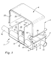
- FIG. 1 shows a silencer according to the invention 1 a housing 2, which is constructed with two shells.
- the Silencer 1 is for installation in a not shown Exhaust system of an internal combustion engine, in particular one Motor vehicle provided.
- This housing 2 thus has a trough-shaped base part 3 and a matching, trough-shaped cover 4.
- the bottom part 3 has a bottom 5 on that of two opposite end walls 6 and 7 and two, extending between the end walls 6, 7, opposite side walls 8 bordered is. In Fig. 1 the cut is made so that only one of the side walls 8 is shown. In this way the bottom part 3 receives a self-supporting structure.
- the bottom part 3 is made of a metal, e.g. made of sheet steel. A deep-drawing process is preferred here the end walls 6, 7 and the side walls 8 from the bottom 5 be formed.
- a U-profile part 9 is inserted approximately in the middle, which is made of metal and its U-leg two Cross walls, namely a first cross wall 10 and a second Form transverse wall 11, which are in the bottom part 3 of each other spaced and extend parallel to the end walls 6 or 7.
- the U-profile part 9 is at its base 12 with the Bottom 5, e.g. by a welded connection, firmly connected.
- the transverse walls 10 and 11 can also be installed as individual parts in the bottom part 3 his.
- the silencer 1 also includes an inflow pipe 13, through which the hot exhaust gases and the sound to be damped in enter the housing 2.
- This inflow pipe 13 penetrates the first end wall 6 facing the viewer and both transverse walls 10 and 11 and ends with one only partially visible mouth end 14 in an inflow space 15.
- This Inflow space 15 is laterally from the side walls 8, the second transverse wall 11 and the second facing away from the viewer End wall 7 limited.
- the inflow pipe 13 is with the first End wall 6 firmly connected, in particular welded or soldered.
- the inflow pipe 13 is supported on the transverse walls 10 and 11 in the radial direction, without one in the axial direction of the inflow pipe 13 effective fixation between the inflow tube 13 and the transverse walls 10 and 11 must be provided.
- the inflow pipe 13 in the transverse walls 10 and 11 a kind of sliding seat.
- This storage enables relative movements between the inflow pipe 13 and the transverse walls 10 and 11, which can occur due to thermal loads.
- the inflow pipe 13 can also be fixed to the transverse walls 10 and 11, wherein thermal expansion of the Inflow pipe 13 then by elastic deformation of the transverse walls 10,11 be included.
- the Muffler 1 has a discharge pipe 16 which is the second end wall 7 and the two transverse walls 11 and 10 penetrates and with a mouth end 17 opens into an outflow chamber 18.
- This Outflow chamber 18 is laterally through the side walls 8, the first End wall 3 and the first transverse wall 10 limited. That too Outflow pipe 16 is fixedly connected to the second end wall 7 and mounted axially displaceably in the transverse walls 10, 11 or firmly connected, in both cases a radial Support of the outflow pipe 16 on the transverse walls 10 and 11 is realized.
- the pipes run 13 and 16 parallel to each other and parallel to the floor 5.
- the tubes 13 and 16 are arranged relatively close to the bottom 5.
- the mouth ends are 14 and 17, respectively aligned with the floor 5 to deal with the hot exhaust gases to target the heat-resistant floor 5.
- this arrangement enables the expulsion of Condensate, which is at the bottom 5, e.g. in winter, accumulate can.
- the transverse walls 10 and 11 separate in the housing 2 between the Inflow space 15 and the outflow space 18 also an intermediate space 19 from. Furthermore, it is axially open on both sides Coupling tube 20 is provided, the two transverse walls 10 and 11 penetrates and thus a communicating connection between inflow space 15 and outflow space 18. To this In the inflow space 15 and in the outflow space 18 several cross-sectional jumps within the flow path of the exhaust gases trained in a sound transmission counteract the outflow pipe 16.
- the coupling tube 20 is also made of a heat-resistant metal and is preferably with at least one of the transverse walls 10 and 11 firmly connected. Thus, the coupling tube 20 also contributes Increase the rigidity of the bottom part 3.
- Coupling tube 20 perforated in the area of the space 19 designed.
- Embodiments are also possible in which alternatively or in addition to the coupling pipe 20, the inflow pipe 13 and / or the outflow pipe 16 in the region of the intermediate space 19 and / or the transverse walls 10 and / or 11 perforated are designed.
- This coupling tube 20 is in the area of the intermediate space 19 designed perforated and accordingly has one Plurality of radial openings 21.
- the one in the individual Rooms 15, 18 and 19 can propagate sound appropriate measures are dampened.
- the achievable damping effect especially the frequencies to be attenuated are about sizing the volumes of each Rooms 15, 18, 19 can be influenced.
- the occurring in the exhaust system Sound waves require relatively large-volume rooms 15, 18, 19 for their damping.
- the housing needs 2 of the silencer 1 has a relatively large volume. This volume is provided by the cover 4.
- This Lid 4 is made according to the invention from a plastic. This is possible because all gas-carrying elements and areas of the silencer 1 essentially in Bottom part 3 are arranged or formed.
- the leadership the hot exhaust gases are specifically so that only the heat-resistant metal parts of the silencer 1, So bottom part 3, tube 13, 16, 20 and transverse walls 10, 11, directly be exposed to the hot exhaust gases.
- the purpose of the coupling tube 20 is also relatively close to the bottom 5 arranged and parallel to the inflow pipe 13 or to the outflow pipe 16 aligned.
- End walls 6 and 7 with respect to a measured perpendicular to the floor 5 Height have a greater height than the side walls 8. This ensures that the hottest Set the silencer 1 a relatively large distance to cover 4.
- the end walls 6 and 7 are special can be cooled as far as possible by applying a headwind, that the attached cover 4 no critical temperatures is exposed.
- the less highly educated Side walls 8 allow the cover 4 to be enlarged this area to make the weight advantage of the lid 4 stronger to be able to exploit.
- the cover 4 is on lined on the inside with an inner lining 22.
- This inner lining 22 suitably consists of a sound absorbing and thermal insulating material, which on the one hand, the spreading in rooms 15, 18, 19 Absorbs sound and on the other hand overheats the Plastic lid 4 is prevented.
- the inner lining 22 consists, for example, of a temperature-resistant felt on the inside of the cover 4 is glued or melted.
- a temperature-resistant felt on the inside of the cover 4 is glued or melted.
- Such one Felt can in particular be made of E-glass fibers or quartz glass fibers getting produced.
- Such a felt can both be needled or sewn filament as well as carpet-like, standing perpendicular to the respective contact surface Fibers with adhesive or connection on the back are made. In addition to their thermal insulation effect these felts also dampen the pressure pulsations within the respective room 15, 18, 19 by absorption.
- Fig. 1 extend the transverse walls 10 and 11 each from the bottom 5 to one Blanket 23 on the inside of the lid 4.
- End edges 24 of the transverse walls 10 facing away from the base part 3 and 11 in corresponding receptacles in the cover 4 and / or in the inner panel 22 may be included.
- the individual rooms 15,18,19 also within the Lid 4 are sufficiently sealed against each other to avoid hot leakage flows in the plastic cover 4.
- base part 3 and cover 4 for example by gluing and / or rivets and / or positive locking, e.g. through attached clinging C-profiles, firmly connected become.
- one in the region of the frets 25 Tongue and groove connection to realize, in which the one collar contains a groove in which one formed on the other fret Spring or in the other formed as a spring collar is insertable.
- a form-fitting Locking and / or gluing may be provided.
- the plastic collar of the cover 4 melted onto the metal collar of the base part 3 or with this be welded, creating a material connection is achieved. If necessary, can be riveted in any case and / or screwed.
- the spaces 15 form 18, 19 each reflection chambers, which also by the Interior trim 22 are damped.
- an intermediate floor 27 is arranged acoustically permeable by means of a plurality of openings 28 is designed.
- the intermediate floor 27 can be in the region of the federal government 25 End walls 6, 7 and optionally also on the transverse walls 10 and 11 be attached.
- the mezzanine 27 is preferably made of metal.
- the intermediate floor 27 is in the lid 4 from the bottom part 3 facing away cavity 29 separated between the intermediate floor 27 and the ceiling 23 extends.
- this cavity 29 with a sound absorbing material 30 filled or filled in, that in the present example can be formed by a full body.
- a sound absorbing Material is also suitable for temperature resistance Felt of the above kind as well as one suitable, heat-resistant wool.
- the sound absorbing Material 30 is in the cavity by means of the intermediate floor 27 29 positioned such that entrainment of the possibly loose Materials, e.g. Felt or wool, with the exhaust gas prevented becomes.
- Fig. 2 3 fasteners on the bottom part 31 attack, which are here in the form of rods, which are welded to the bottom part 3, for example.
- damping means e.g. Suspension rubbers on a vehicle body, not shown be attached.
- conventional suspension methods are used, which makes the Handling and attachment of the equipped with the silencer 1 Exhaust system simplified.
- the base part 3 As materials for the base part 3 are particularly suitable Wise single or multi-layer stainless steel sheets or aluminized Steel sheets.
- Temperature-resistant, sprayable are suitable for the cover 4 Plastics, e.g. Polyphenylene sulfides, polyarsulfones, Polyether sulfones, polyether ether ketones, polyether ketone ketones, Polyimides, bismaleimides and cyanate esters.
- Plastics e.g. Polyphenylene sulfides, polyarsulfones, Polyether sulfones, polyether ether ketones, polyether ketone ketones, Polyimides, bismaleimides and cyanate esters.
- reinforcing fibers made of glass aramid, ceramic or coal in the spray material come. It is also possible to use reinforcing fiber fabrics arrange in the injection mold and then with the respective Overmolding plastic.
- thermoplastics thermosets are also used, which are also expedient are fiber reinforced. For example, polyester, Epoxy, phenolic and melamine resins.
- plastic cover 4 Manufacturing process spraying in molds, blowing out Preforming, pulling in the soft state, inserting impregnated Fiber fabrics (prepregs) and heating in the mold, laminating of fiber laid in the form (rolling, spraying), the respective reaction is triggered with light or heat.
Landscapes
- Engineering & Computer Science (AREA)
- Chemical & Material Sciences (AREA)
- Combustion & Propulsion (AREA)
- Mechanical Engineering (AREA)
- General Engineering & Computer Science (AREA)
- Exhaust Silencers (AREA)
Abstract
Description
- Fig. 1
- eine perspektivische Ansicht auf einen geschnittenen Schalldämpfer nach der Erfindung, wobei ein Deckel von einem Unterteil abgehoben ist,
- Fig. 2
- eine perspektivische Ansicht auf ein Unterteil des erfindungsgemäßen Schalldämpfers, jedoch bei einer anderen Ausführungsform,
- Fig. 3
- eine perspektivische Ansicht auf einen Schalldämpfer wie in Fig. 2, jedoch bei einer geschnittenen Darstellung und mit vom Unterteil abgehobenem Deckel.
- 1
- Schalldämpfer
- 2
- Gehäuse
- 3
- Bodenteil
- 4
- Deckel
- 5
- Boden
- 6
- erste Stirnwand
- 7
- zweite Stirnwand
- 8
- Seitenwand
- 9
- U-Profilteil
- 10
- erste Querwand
- 11
- zweite Querwand
- 12
- Basis von 9
- 13
- Zuströmrohr
- 14
- Mündungsende von 13
- 15
- Zuströmraum
- 16
- Abströmrohr
- 17
- Mündungsende von 16
- 18
- Abströmraum
- 19
- Zwischenraum
- 20
- Kopplungsrohr
- 21
- radiale Öffnung von 20
- 22
- Innenverkleidung von 4
- 23
- Decke von 4
- 24
- Oberkante von 10,11
- 25
- Bund von 3
- 26
- Bund von 4
- 27
- Zwischenboden
- 28
- Öffnung in 27
- 29
- Hohlraum in 4
- 30
- schallabsorbierendes Material
- 31
- Befestigungsmittel
- 32
- Schürze
Claims (12)
- Schalldämpfer für einen Abgasstrang einer Brennkraftmaschine, insbesondere eines Kraftfahrzeugs,mit einem wannenförmigen, selbsttragenden Bodenteil (3) aus Metall, das einen von zwei einander gegenüberliegenden Seitenwänden (8) und zwei einander gegenüberliegenden Stirnwänden (6, 7) eingefaßten Boden (5) aufweist und das wenigstens eine Querwand (10, 11) enthalt, die mit dem Boden (5) und/oder mit den Seitenwänden (8) fest verbunden ist und im wesentlichen parallel zu den Stirnwänden (6, 7) verläuft,mit einem Zuströmrohr (13) das die erste Stirnwand (6) und die wenigstens eine Querwand (10, 11) durchdringt, mit der ersten Stirnwand (6) fest verbunden ist und sich radial an der wenigstens einen Querwand (10, 11) abstützt,mit einem Abströmrohr (16), das die zweite Stirnwand (7) und die wenigstens eine Querwand (10, 11) durchdringt, mit der zweiten Stirnwand (7) fest verbunden ist und sich radial an der wenigstens einen Querwand (10, 11) abstützt,mit einem wannenförmigen Deckel (4) aus Kunststoff, der das Bodenteil (3) gasdicht verschließt.
- Schalldämpfer nach Anspruch 1,
dadurch gekennzeichnet, daß von Abgas durchströmte Bereiche des Schalldämpfers (1) im wesentlichen im Bodenteil (3) angeordnet und/oder ausgebildet sind. - Schalldämpfer nach Anspruch 1 oder 2,
dadurch gekennzeichnet, daß zwei zueinander parallele Querwände (10, 11) vorgesehen sind, die beide vom Zuströmrohr (13) und vom Abströmrohr (16) durchdrungen sind und die im Inneren des Schalldämpfers (1) einen von der zweiten Stirnwand (7) begrenzten Zuströmraum (15), in den das Zuströmrohr (13) einmündet, einen von der ersten Stirnwand (6) begrenzten Abströmraum (18), in den das Abströmrohr (16) einmündet, und einen von den Querwänden (10, 11) begrenzten Zwischenraum (19) voneinander trennen, wobei ein beidseitig offenes Kopplungsrohr (20) beide Querwände (10, 11) durchdringt und den Zuströmraum (15) mit dem Abströmraum (18) kommunizierend verbindet. - Schalldämpfer nach Anspruch 3,
dadurch gekennzeichnet, daß das Kopplungsrohr (20) in der Nähe des Bodens (5), zumindest im wesentlichen innerhalb des Bodenteils (3) angeordnet ist. - Schalldämpfer nach einem der Ansprüche 1 bis 4,
dadurch gekennzeichnet, daß der Deckel (4) an seiner Innenseite mit einer Innenverkleidung (22) ausgekleidet ist, die aus einem schallabsorbierenden und/oder thermoisolierenden Material besteht. - Schalldämpfer nach einem der Ansprüche 1 bis 5,
dadurch gekennzeichnet, daß die Stirnwände (6, 7) des Bodenteils (3) jeweils eine größere Höhe aufweisen als die Seitenwände (8) des Bodenteils (3), wobei die Höhe im wesentlichen senkrecht zum Boden (5) des Bodenteils (3) gemessen ist. - Schalldämpfer nach einem der Ansprüche 1 bis 6,
dadurch gekennzeichnet, daß sich jede Querwand (10, 11) vom Boden (5) bis zu einer Decke (23) des Deckels (4) erstreckt. - Schalldämpfer nach einem der Ansprüche 1 bis 6,
dadurch gekennzeichnet, daß im Inneren des Schalldämpfers (1) zwischen dem Boden (5) und einer Decke (23) des Deckels (4) ein akustisch durchlässiger Zwischenboden (27) angeordnet ist, wobei sich jede Querwand (10, 11) vom Boden (5) bis zum Zwischenboden (27) erstreckt, wobei der Zwischenboden (27) im Deckel (4) einen vom Bodenteil (3) abgewandten Hohlraum (29) abtrennt, der mit einem schallabsorbierenden Material (30) be- und/oder ausgefüllt ist. - Schalldämpfer nach einem der Ansprüche 1 bis 8,
dadurch gekennzeichnet, daß Zuströmrohr (13) und Abströmrohr (16) und - soweit vorhanden - das Kopplungsrohr (20) im wesentlichen parallel zum Boden (5) verlaufen. - Schalldämpfer nach einem der Ansprüche 1 bis 9,
dadurch gekennzeichnet, daß die Außenkontur des Deckels (4) an die jeweilige Einbausituation des Schalldämpfers (1) angepaßt ist. - Schalldämpfer nach einem der Ansprüche 1 bis 10,
dadurch gekennzeichnet, daß der Schalldämpfer (1) mit Befestigungsmitteln (31) an einer Fahrzeugkarosserie befestigt ist, wobei die Befestigungsmittel (31) schalldämpferseitig nur am Bodenteil (3) angreifen. - Schalldämpfer nach einem der Ansprüche 1 bis 11,
dadurch gekennzeichnet, daß der Deckel (4) mit dem Bodenteil (3) verbunden ist durch Verkleben und/oder durch wenigstens eine auf nach außen abstehende Bünde (25,26) von Deckel (4) und Bodenteil (3) aufgesteckte C-förmige Klammer und/oder durch eine Nut-Feder-Verbindung und/oder durch eine Rastverbindung und/oder durch Aufschmelzen des Kunststoff-Deckels (4) auf das Metall-Bodenteil (3) und/oder durch Anschweißen des Kunststoff-Deckels (4) am Metall-Bodenteil (3) und/oder durch Nieten und/oder durch Schrauben.
Applications Claiming Priority (2)
| Application Number | Priority Date | Filing Date | Title |
|---|---|---|---|
| DE10120974 | 2001-04-27 | ||
| DE10120974A DE10120974C1 (de) | 2001-04-27 | 2001-04-27 | Abgasschalldämpfer |
Publications (2)
| Publication Number | Publication Date |
|---|---|
| EP1253302A1 true EP1253302A1 (de) | 2002-10-30 |
| EP1253302B1 EP1253302B1 (de) | 2004-08-18 |
Family
ID=7683130
Family Applications (1)
| Application Number | Title | Priority Date | Filing Date |
|---|---|---|---|
| EP02007535A Expired - Lifetime EP1253302B1 (de) | 2001-04-27 | 2002-04-03 | Abgasschalldämpfer |
Country Status (2)
| Country | Link |
|---|---|
| EP (1) | EP1253302B1 (de) |
| DE (2) | DE10120974C1 (de) |
Families Citing this family (9)
| Publication number | Priority date | Publication date | Assignee | Title |
|---|---|---|---|---|
| DE10243644B4 (de) * | 2002-09-19 | 2008-09-11 | Roth-Technik Austria Ges.M.B.H. | Lösbare Verbindung von Profilbauteilen |
| DE10353594B4 (de) * | 2003-11-17 | 2013-08-01 | Friedrich Boysen Gmbh & Co. Kg | Schalldämpfer |
| US7942237B2 (en) | 2006-04-12 | 2011-05-17 | Ocv Intellectual Capital, Llc | Long fiber thermoplastic composite muffler system with integrated reflective chamber |
| US7934580B2 (en) | 2006-04-12 | 2011-05-03 | Ocv Intellectual Capital, Llc | Long fiber thermoplastic composite muffler system |
| US7730996B2 (en) | 2006-04-12 | 2010-06-08 | Ocv Intellectual Capital, Llc | Long fiber thermoplastic composite muffler system with integrated crash management |
| DE102006017812C5 (de) | 2006-04-13 | 2024-08-01 | Faurecia Emissions Control Technologies, Germany Gmbh | Schalldämpfer für eine Abgasanlage |
| DE102006033053B3 (de) * | 2006-07-14 | 2007-09-06 | Benteler Automobiltechnik Gmbh | Kraftfahrzeug-Schalldämpfer |
| DE102009009168A1 (de) * | 2009-02-16 | 2010-08-19 | Man Turbo Ag | Schalldämpfer für eine Strömungs- oder Kolbenmaschine |
| DE102011081310B4 (de) * | 2011-08-22 | 2013-03-07 | J. Eberspächer GmbH & Co. KG | Schalldämpfer und Verfahren |
Citations (6)
| Publication number | Priority date | Publication date | Assignee | Title |
|---|---|---|---|---|
| GB2129490A (en) * | 1982-10-26 | 1984-05-16 | Alan William Richards | Corrosion resistant exhaust silencers |
| GB2143275A (en) * | 1983-07-02 | 1985-02-06 | Production Eng Res | Silencer for exhaust gases |
| EP0337877A1 (de) * | 1988-04-12 | 1989-10-18 | Regie Nationale Des Usines Renault | Schalldämpfer für Explosionsmotoren |
| US5147987A (en) * | 1989-04-28 | 1992-09-15 | Arvin Industries, Inc. | Muffler assembly |
| US5248738A (en) * | 1989-10-20 | 1993-09-28 | Toyoda Gosei Co., Ltd. | Vibration-damping resin molded products formed of a mixture of nylon 6 resin, a xylene diamine based nylon resin, and a nylon 66 resin |
| US5521341A (en) * | 1993-05-28 | 1996-05-28 | Firma Carl Freudenberg | Sound-attenuator |
-
2001
- 2001-04-27 DE DE10120974A patent/DE10120974C1/de not_active Expired - Fee Related
-
2002
- 2002-04-03 EP EP02007535A patent/EP1253302B1/de not_active Expired - Lifetime
- 2002-04-03 DE DE50200841T patent/DE50200841D1/de not_active Expired - Lifetime
Patent Citations (6)
| Publication number | Priority date | Publication date | Assignee | Title |
|---|---|---|---|---|
| GB2129490A (en) * | 1982-10-26 | 1984-05-16 | Alan William Richards | Corrosion resistant exhaust silencers |
| GB2143275A (en) * | 1983-07-02 | 1985-02-06 | Production Eng Res | Silencer for exhaust gases |
| EP0337877A1 (de) * | 1988-04-12 | 1989-10-18 | Regie Nationale Des Usines Renault | Schalldämpfer für Explosionsmotoren |
| US5147987A (en) * | 1989-04-28 | 1992-09-15 | Arvin Industries, Inc. | Muffler assembly |
| US5248738A (en) * | 1989-10-20 | 1993-09-28 | Toyoda Gosei Co., Ltd. | Vibration-damping resin molded products formed of a mixture of nylon 6 resin, a xylene diamine based nylon resin, and a nylon 66 resin |
| US5521341A (en) * | 1993-05-28 | 1996-05-28 | Firma Carl Freudenberg | Sound-attenuator |
Also Published As
| Publication number | Publication date |
|---|---|
| EP1253302B1 (de) | 2004-08-18 |
| DE10120974C1 (de) | 2002-05-23 |
| DE50200841D1 (de) | 2004-09-23 |
Similar Documents
| Publication | Publication Date | Title |
|---|---|---|
| EP2203632B1 (de) | Abgasleitungsbauteil | |
| DE102012201725B4 (de) | Aktiver Schalldämpfer | |
| EP1055804B1 (de) | Aktiver Abgasschalldämpfer | |
| EP1253302B1 (de) | Abgasschalldämpfer | |
| WO1994008169A1 (de) | Flexible verbindungsanordnung für zwei rohrteile, insbesondere bei abgasanlagen von kraftfahrzeugen | |
| DE102010037162A1 (de) | Dämpfungselement für Entkopplungselemente, insbesondere für Membranbälge | |
| WO2012168039A1 (de) | Schalldämpfer und herstellungsverfahren | |
| DE69726251T2 (de) | Kraftfahrzeug-Stossstange und -Schalldämpfer-Kombination | |
| DE102008056350B4 (de) | Schalldämpfer und zugehöriges Herstellungsverfahren | |
| EP3921191A1 (de) | Luftkanal für ein kraftfahrzeug sowie verfahren für seine herstellung | |
| DE102014221151A1 (de) | Komponente einer Abgasanlage | |
| EP2639423B1 (de) | Schalldämpfer-einheit | |
| WO2016045661A1 (de) | Heizgerät-abgasrohranordnung mit integriertem schalldämpfer und herstellungsverfahren dafür | |
| DE102004029221A1 (de) | Vorrichtung zur Schalldämpfung und Vorrichtung zur Leitung eines Fluids | |
| DE3839243A1 (de) | Schalldaempfer fuer heizgeraete | |
| DE3326260A1 (de) | Auspuffleitung | |
| WO2007065491A1 (de) | Schutzschild zur thermischen und akustischen abschirmung von bauteilen einer verbrennungskraftmaschine | |
| DE10001287A1 (de) | Abgaskrümmer | |
| DE102008033802B4 (de) | Ansaugleitungselement für eine Verbrennungskraftmaschine | |
| DE102009052644B4 (de) | Wärmeabschirmungsblech für Abgasanlagen von Kraftfahrzeugen | |
| DE102007042869A1 (de) | Vorrichtung zur Reduzierung von Geräuschemissionen | |
| EP1416148A2 (de) | Schallreduzierendes Bauteil für ein Luftführungsrohr | |
| DE3243631A1 (de) | Abgasschalldaempfer | |
| DE102015224453A1 (de) | Schalldämpfer und Herstellungsverfahren | |
| EP1838555A2 (de) | Strukturbauteil, insbesondere abschirmteil |
Legal Events
| Date | Code | Title | Description |
|---|---|---|---|
| PUAI | Public reference made under article 153(3) epc to a published international application that has entered the european phase |
Free format text: ORIGINAL CODE: 0009012 |
|
| 17P | Request for examination filed |
Effective date: 20020821 |
|
| AK | Designated contracting states |
Kind code of ref document: A1 Designated state(s): AT BE CH CY DE DK ES FI FR GB GR IE IT LI LU MC NL PT SE TR |
|
| AX | Request for extension of the european patent |
Free format text: AL;LT;LV;MK;RO;SI |
|
| AKX | Designation fees paid |
Designated state(s): DE FR GB IT SE |
|
| 17Q | First examination report despatched |
Effective date: 20031104 |
|
| GRAP | Despatch of communication of intention to grant a patent |
Free format text: ORIGINAL CODE: EPIDOSNIGR1 |
|
| GRAP | Despatch of communication of intention to grant a patent |
Free format text: ORIGINAL CODE: EPIDOSNIGR1 |
|
| GRAS | Grant fee paid |
Free format text: ORIGINAL CODE: EPIDOSNIGR3 |
|
| GRAA | (expected) grant |
Free format text: ORIGINAL CODE: 0009210 |
|
| AK | Designated contracting states |
Kind code of ref document: B1 Designated state(s): DE FR GB IT SE |
|
| REG | Reference to a national code |
Ref country code: GB Ref legal event code: FG4D Free format text: NOT ENGLISH |
|
| REG | Reference to a national code |
Ref country code: IE Ref legal event code: FG4D Free format text: GERMAN |
|
| REF | Corresponds to: |
Ref document number: 50200841 Country of ref document: DE Date of ref document: 20040923 Kind code of ref document: P |
|
| GBT | Gb: translation of ep patent filed (gb section 77(6)(a)/1977) |
Effective date: 20040908 |
|
| REG | Reference to a national code |
Ref country code: SE Ref legal event code: TRGR |
|
| REG | Reference to a national code |
Ref country code: IE Ref legal event code: FD4D |
|
| PLBE | No opposition filed within time limit |
Free format text: ORIGINAL CODE: 0009261 |
|
| STAA | Information on the status of an ep patent application or granted ep patent |
Free format text: STATUS: NO OPPOSITION FILED WITHIN TIME LIMIT |
|
| ET | Fr: translation filed | ||
| 26N | No opposition filed |
Effective date: 20050519 |
|
| PGFP | Annual fee paid to national office [announced via postgrant information from national office to epo] |
Ref country code: SE Payment date: 20090427 Year of fee payment: 8 |
|
| EUG | Se: european patent has lapsed | ||
| PG25 | Lapsed in a contracting state [announced via postgrant information from national office to epo] |
Ref country code: SE Free format text: LAPSE BECAUSE OF NON-PAYMENT OF DUE FEES Effective date: 20100404 |
|
| REG | Reference to a national code |
Ref country code: GB Ref legal event code: 732E Free format text: REGISTERED BETWEEN 20130905 AND 20130911 |
|
| REG | Reference to a national code |
Ref country code: DE Ref legal event code: R082 Ref document number: 50200841 Country of ref document: DE Representative=s name: BRP RENAUD & PARTNER, DE |
|
| REG | Reference to a national code |
Ref country code: DE Ref legal event code: R081 Ref document number: 50200841 Country of ref document: DE Owner name: EBERSPAECHER EXHAUST TECHNOLOGY GMBH & CO. KG, DE Free format text: FORMER OWNER: J. EBERSPAECHER GMBH & CO. KG, 73730 ESSLINGEN, DE Effective date: 20131022 Ref country code: DE Ref legal event code: R082 Ref document number: 50200841 Country of ref document: DE Representative=s name: BRP RENAUD & PARTNER, DE Effective date: 20131022 Ref country code: DE Ref legal event code: R082 Ref document number: 50200841 Country of ref document: DE Representative=s name: BRP RENAUD UND PARTNER MBB RECHTSANWAELTE PATE, DE Effective date: 20131022 Ref country code: DE Ref legal event code: R082 Ref document number: 50200841 Country of ref document: DE Representative=s name: BRP RENAUD UND PARTNER MBB, DE Effective date: 20131022 |
|
| REG | Reference to a national code |
Ref country code: FR Ref legal event code: CD Owner name: EBERSPACHER CLIMATE CONTROL SYSTEMS GMBH & CO. KG Effective date: 20131129 |
|
| REG | Reference to a national code |
Ref country code: FR Ref legal event code: TP Owner name: EBERSPACHER EXHAUST TECHNOLOGY GMBH & CO. KG, DE Effective date: 20140204 |
|
| REG | Reference to a national code |
Ref country code: FR Ref legal event code: PLFP Year of fee payment: 15 |
|
| REG | Reference to a national code |
Ref country code: FR Ref legal event code: PLFP Year of fee payment: 16 |
|
| REG | Reference to a national code |
Ref country code: FR Ref legal event code: PLFP Year of fee payment: 17 |
|
| PGFP | Annual fee paid to national office [announced via postgrant information from national office to epo] |
Ref country code: DE Payment date: 20180423 Year of fee payment: 17 |
|
| PGFP | Annual fee paid to national office [announced via postgrant information from national office to epo] |
Ref country code: IT Payment date: 20180420 Year of fee payment: 17 Ref country code: FR Payment date: 20180424 Year of fee payment: 17 |
|
| PGFP | Annual fee paid to national office [announced via postgrant information from national office to epo] |
Ref country code: GB Payment date: 20180403 Year of fee payment: 17 |
|
| REG | Reference to a national code |
Ref country code: DE Ref legal event code: R119 Ref document number: 50200841 Country of ref document: DE |
|
| GBPC | Gb: european patent ceased through non-payment of renewal fee |
Effective date: 20190403 |
|
| PG25 | Lapsed in a contracting state [announced via postgrant information from national office to epo] |
Ref country code: DE Free format text: LAPSE BECAUSE OF NON-PAYMENT OF DUE FEES Effective date: 20191101 Ref country code: GB Free format text: LAPSE BECAUSE OF NON-PAYMENT OF DUE FEES Effective date: 20190403 |
|
| PG25 | Lapsed in a contracting state [announced via postgrant information from national office to epo] |
Ref country code: IT Free format text: LAPSE BECAUSE OF NON-PAYMENT OF DUE FEES Effective date: 20190403 |
|
| PG25 | Lapsed in a contracting state [announced via postgrant information from national office to epo] |
Ref country code: FR Free format text: LAPSE BECAUSE OF NON-PAYMENT OF DUE FEES Effective date: 20190430 |