EP1253103A2 - Flurförderzeug mit einer federnd aufgehängten Lenkachse - Google Patents
Flurförderzeug mit einer federnd aufgehängten Lenkachse Download PDFInfo
- Publication number
- EP1253103A2 EP1253103A2 EP02008750A EP02008750A EP1253103A2 EP 1253103 A2 EP1253103 A2 EP 1253103A2 EP 02008750 A EP02008750 A EP 02008750A EP 02008750 A EP02008750 A EP 02008750A EP 1253103 A2 EP1253103 A2 EP 1253103A2
- Authority
- EP
- European Patent Office
- Prior art keywords
- vehicle
- industrial truck
- transmission element
- steering axle
- truck according
- Prior art date
- Legal status (The legal status is an assumption and is not a legal conclusion. Google has not performed a legal analysis and makes no representation as to the accuracy of the status listed.)
- Granted
Links
Images

Classifications
-
- B—PERFORMING OPERATIONS; TRANSPORTING
- B66—HOISTING; LIFTING; HAULING
- B66F—HOISTING, LIFTING, HAULING OR PUSHING, NOT OTHERWISE PROVIDED FOR, e.g. DEVICES WHICH APPLY A LIFTING OR PUSHING FORCE DIRECTLY TO THE SURFACE OF A LOAD
- B66F9/00—Devices for lifting or lowering bulky or heavy goods for loading or unloading purposes
- B66F9/06—Devices for lifting or lowering bulky or heavy goods for loading or unloading purposes movable, with their loads, on wheels or the like, e.g. fork-lift trucks
- B66F9/075—Constructional features or details
- B66F9/07568—Steering arrangements
-
- B—PERFORMING OPERATIONS; TRANSPORTING
- B60—VEHICLES IN GENERAL
- B60G—VEHICLE SUSPENSION ARRANGEMENTS
- B60G9/00—Resilient suspensions of a rigid axle or axle housing for two or more wheels
- B60G9/02—Resilient suspensions of a rigid axle or axle housing for two or more wheels the axle or housing being pivotally mounted on the vehicle, e.g. the pivotal axis being parallel to the longitudinal axis of the vehicle
-
- B—PERFORMING OPERATIONS; TRANSPORTING
- B66—HOISTING; LIFTING; HAULING
- B66F—HOISTING, LIFTING, HAULING OR PUSHING, NOT OTHERWISE PROVIDED FOR, e.g. DEVICES WHICH APPLY A LIFTING OR PUSHING FORCE DIRECTLY TO THE SURFACE OF A LOAD
- B66F9/00—Devices for lifting or lowering bulky or heavy goods for loading or unloading purposes
- B66F9/06—Devices for lifting or lowering bulky or heavy goods for loading or unloading purposes movable, with their loads, on wheels or the like, e.g. fork-lift trucks
- B66F9/075—Constructional features or details
- B66F9/07586—Suspension or mounting of wheels on chassis
Definitions
- the invention relates to an industrial truck, in particular a counterbalance forklift, with a steering axle that is attached to a longitudinal rocker and together with this is pivotable about a vehicle transverse axis, the longitudinal rocker being a guide has a rotational degree of freedom with respect to a vehicle longitudinal axis features.
- a generic industrial truck is known from DE 197 32 400 A1.
- the rear steering axle is on one Supporting yoke swinging, its vertical position to the vehicle frame by means of of a hydraulic cylinder can be changed. The to compensate for unevenness The pendulum movement of the axle provided on the road surface remains unaffected.
- the present invention is based on the object of an improved industrial truck of the type mentioned at the outset to provide a high level of driving comfort and has high driving safety.
- This object is achieved in that the steering axis on both sides the longitudinal axis of the vehicle in each case by means of an elastic force transmission element on the vehicle frame or a support frame connected to the vehicle frame is supported.
- vehicle frame includes in the case of a counterbalance forklift of course also the counterweight.
- the steering axle and / or the power transmission elements can also on the counterweight on the invention Be attached way.
- a sprung guidance of the steering axle is achieved by the invention.
- This can the vertical movement of the wheels attached to the steering axle is independent of one another take place, which results in improved driving comfort. It can also Spring movement of the wheels can be influenced in certain driving conditions Increase driving stability.
- the structure of the system is robust and the same simple as in the known industrial trucks of the prior art.
- the power transmission element is expediently in the region of the axle end connected to the steering axle. This results in a large lever arm which attacks the power transmission element, so that the supporting forces are minimized become.
- the power transmission element can be blocked, in particular hydraulically blocked.
- the elastic power transmission elements can be increased.
- the steering axis will to a certain extent "locked" to the vehicle frame.
- the power transmission element is adjustable in length, in particular hydraulically is adjustable in length, the distance of the vehicle frame to the road in Range of the steering axis can be varied.
- the steering axis is arranged on the rear, can there is no need to tilt the mast. Furthermore Then there is no need for costly storage of the mast, which is consequently on can be easily connected to the vehicle frame.
- the spring stiffness and / or the damping constant of Power transmission element is adjustable. By changing these two parameters can the elasticity or vibration properties of the power transmission element optimal to the respective driving and loading condition of the industrial truck be adjusted.
- the power transmission element is expediently designed as a spring-damper unit educated.
- this is a hydraulic cylinder-piston unit with integrated damping device and with parallel spring, for example a shock absorber.
- the guide is designed as a rotary guide which is a stator unit and one relative thereto about the vehicle longitudinal axis has rotatable rotor unit, the rotor unit with the steering axis and the Stator unit is connected to the vehicle frame.
- stator unit by means of a joint through which the vehicle's transverse axis extends extends to be connected to the vehicle frame.
- the joint can be designed in the usual way, and z.
- the stator unit have penetrating cross pin, the center line of which is coaxial with the transverse axis of the vehicle is and which is supported in two lateral bearing blocks, which with the Vehicle frames are connected.
- a design of the rotary guide that is favorable in terms of low construction costs provides that the rotor unit has a hollow cylindrical recess in which a cylindrical pin of the stator unit is mounted.
- the industrial truck according to the invention is preferably used as a counterbalance forklift formed of a vehicle frame 1 and in the present embodiment has a rear steering axle 2. At the axle ends of the steering axle 2 is in each case a wheel 3 is arranged, of which only one is shown in the figures.
- the steering axle 2 consists of an axle body 4 on which a steering unit 5 (here: Steering cylinder) and tie rods 6 are attached. There is one on each end of the axle steerable wheel carrier 7 attached.
- a steering unit 5 here: Steering cylinder
- tie rods 6 There is one on each end of the axle steerable wheel carrier 7 attached.
- the steering axis 2 is attached to a centrally arranged longitudinal rocker 8, which with a transversely arranged receptacle 1a of the vehicle frame 1 is connected such that swivel the longitudinal rocker 8 together with the steering axis 2 about a vehicle transverse axis can.
- the longitudinal rocker 8 is connected to the receptacle by means of a joint 9 1a or the vehicle frame 1 connected.
- the joint 9 consists of two Bearing blocks 9a and 9b, which are connected to the receptacle 1a, and a cross pin 10, which connects the longitudinal rocker 8 to the bearing blocks 9a and 9b in an articulated manner and whose center line consequently forms the vehicle transverse axis about which the Longitudinal swing arm 8 and the steering axis 2 are pivotable.
- a rotary guide is integrated, which as the pendulum bearing Steering axle 2 is used.
- the rotary guide consists of a stator unit 11a and one Rotor unit 11b, which is relative to the stator unit 11a about a vehicle longitudinal axis is rotatable.
- the stator unit 11 a represents that section of the longitudinal rocker 8, which is connected to the vehicle frame 1 in the manner described above, while the rotor unit 11 b is connected to the drive axle 2.
- the stator unit 11a is designed as a pin, which protrudes into a hollow cylindrical recess of the rotor unit 11b and on which the rotor unit 11b is rotatably supported.
- the steering axle 2 in all embodiments at the axle ends by means of a linearly effective, elastic force transmission element 12 on a support frame 13 supported, which is attached to the receptacle 1 a of the vehicle frame 1.
- a support frame 13 supported, which is attached to the receptacle 1 a of the vehicle frame 1.
- the power transmission elements 12 can also on a not shown in the figures Counterbalance of the forklift.
- the power transmission elements 12 are preferably designed as spring-damper units and each consist of a hydraulic cylinder-piston unit Integrated damping and parallel, in the present embodiment also integrated spring (e.g. gas spring).
- the connection to the steering axle 2 and the support frame 13 is carried out in the manner of a self-aligning support bearing, d. H. in the present Embodiment by means of ball joints 14, 15. Thus, only forces in the longitudinal direction be transmitted.
- the power transmission elements 12 can be blocked and / or adjustable in length his. It is also possible to adjust the spring stiffness and / or the damping constant adjustable.
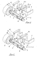
- FIG. 2 represents the reversal of that shown in Figure 1
- the principle of the rotary guide integrated in the longitudinal rocker 8 is:
- the rotor unit 11b formed as a pin which in a hollow cylindrical recess Stator unit 11a protrudes and is rotatably supported there.
- the exemplary embodiment according to FIG. 3 differs from the previous ones Embodiments in that the rotation guide (self-aligning) not through the concentric arrangement of a pin and a hollow cylinder is formed, but a swivel joint is provided on the longitudinal rocker 8 and consists of two bearing blocks 16a and 16b and a longitudinal pin 17.
- the bearing blocks 16a and 16b are connected to the longitudinal rocker 8, while the longitudinal pin 17 is attached to the axle body 4 of the steering axle 2.
Landscapes
- Engineering & Computer Science (AREA)
- Transportation (AREA)
- Structural Engineering (AREA)
- Mechanical Engineering (AREA)
- Civil Engineering (AREA)
- Life Sciences & Earth Sciences (AREA)
- Geology (AREA)
- Forklifts And Lifting Vehicles (AREA)
- Vehicle Body Suspensions (AREA)
Abstract
Description
- Figur 1
- eine perspektivische Ansicht des heckseitigen Rahmenabschnitts eines erfindungsgemäßen Flurförderzeugs,
- Figur 2
- eine perspektivische Ansicht des heckseitigen Rahmenabschnitts einer ersten Variante des erfindungsgemäßen Flurförderzeugs und
- Figur 3
- eine perspektivische Ansicht des heckseitigen Rahmenabschnitts einer zweiten Variante des erfindungsgemäßen Flurförderzeugs.
Claims (10)
- Flurförderzeug, insbesondere Gegengewichts-Gabelstapler, mit einer Lenkachse, die an einer Längsschwinge befestigt und zusammen mit dieser um eine Fahrzeug-Querachse schwenkbar ist, wobei die Längsschwinge eine Führung aufweist, die über einen rotatorischen Freiheitsgrad in Bezug auf eine Fahrzeug-Längsachse verfügt, dadurch gekennzeichnet, dass die Lenkachse (2) beiderseits der Fahrzeug-Längsachse jeweils mittels eines elastischen Kraftübertragungs-Elements (12) am Fahrzeugrahmen (1) oder einem mit dem Fahrzeugrahmen (1) verbundenen Stützrahmen (13) abgestützt ist.
- Flurförderzeug nach Anspruch 1, dadurch gekennzeichnet, dass das Kraftübertragungs-Element (12) jeweils im Bereich des Achsendes mit der Lenkachse (2) verbunden ist.
- Flurförderzeug nach Anspruch 1 oder 2, dadurch gekennzeichnet, dass das Kraftübertragungs-Element (12) blockierbar, insbesondere hydraulisch blockierbar ist.
- Flurförderzeug nach einem der Ansprüche 1 bis 3, dadurch gekennzeichnet, dass das Kraftübertragungs-Element (12) längenverstellbar, insbesondere hydraulisch längenverstellbar ist.
- Flurförderzeug nach einem der Ansprüche 1 bis 4, dadurch gekennzeichnet, dass die Federsteifigkeit und/oder die Dämpfungskonstante des Kraftübertragungs-Elements (12) einstellbar ist.
- Flurförderzeug nach einem der Ansprüche 1 bis 5, dadurch gekennzeichnet, dass das Kraftübertragungs-Element (12) als Feder-Dämpfer-Einheit ausgebildet ist.
- Flurförderzeug nach einem der Ansprüche 1 bis 6, dadurch gekennzeichnet, dass die Führung als Drehführung ausgebildet ist, die eine Statoreinheit (11a) und eine relativ dazu um die Fahrzeug-Längsachse drehbare Rotoreinheit (11b) aufweist, wobei die Rotoreinheit (11b) mit der Lenkachse (2) und die Statoreinheit (11a) mit dem Fahrzeugrahmen (1) verbunden ist.
- Flurförderzeug nach Anspruch 7, dadurch gekennzeichnet, dass die Statoreinheit (11a) mittels eines Gelenks (9), durch das sich die Fahrzeug-Querachse erstreckt, mit dem Fahrzeugrahmen (1) verbunden ist.
- Flurförderzeug nach Anspruch 7 oder 8, dadurch gekennzeichnet, dass die Rotoreinheit (11b) eine hohlzylindrische Ausnehmung aufweist, in der ein zylindrischer Zapfen der Statoreinheit (11b) gelagert ist.
- Flurförderzeug nach Anspruch 7 oder 8, dadurch gekennzeichnet, dass die Rotoreinheit (11b) einen zylindrischen Zapfen aufweist, der in einer hohlzylindrischen Ausnehmung der Statoreinheit (11a) gelagert ist.
Applications Claiming Priority (2)
| Application Number | Priority Date | Filing Date | Title |
|---|---|---|---|
| DE10120598 | 2001-04-26 | ||
| DE2001120598 DE10120598A1 (de) | 2001-04-26 | 2001-04-26 | Flurförderzeug mit einer federnd aufgehängten Lenkachse |
Publications (3)
| Publication Number | Publication Date |
|---|---|
| EP1253103A2 true EP1253103A2 (de) | 2002-10-30 |
| EP1253103A3 EP1253103A3 (de) | 2005-11-16 |
| EP1253103B1 EP1253103B1 (de) | 2007-08-29 |
Family
ID=7682893
Family Applications (1)
| Application Number | Title | Priority Date | Filing Date |
|---|---|---|---|
| EP20020008750 Revoked EP1253103B1 (de) | 2001-04-26 | 2002-04-18 | Flurförderzeug mit einer federnd aufgehängten Lenkachse |
Country Status (2)
| Country | Link |
|---|---|
| EP (1) | EP1253103B1 (de) |
| DE (2) | DE10120598A1 (de) |
Cited By (1)
| Publication number | Priority date | Publication date | Assignee | Title |
|---|---|---|---|---|
| EP3842377A1 (de) * | 2019-12-23 | 2021-06-30 | The Raymond Corporation | Materialhandhabungsfahrzeug mit einer artikulationsachse |
Families Citing this family (1)
| Publication number | Priority date | Publication date | Assignee | Title |
|---|---|---|---|---|
| DE102014113998A1 (de) | 2014-09-26 | 2016-03-31 | Linde Material Handling Gmbh | Federungseinrichtung einer beweglich gelagerten Fahrzeugachse einer mobilen Arbeitsmaschine |
Family Cites Families (5)
| Publication number | Priority date | Publication date | Assignee | Title |
|---|---|---|---|---|
| GB851121A (en) * | 1957-06-26 | 1960-10-12 | Emmanuel Kaye | Improvements in or relating to suspensions for fork and like trucks |
| GB967451A (en) * | 1959-12-01 | 1964-08-19 | Gregory Spencer Jinks | Improvements in or relating to masted lift trucks |
| US3497231A (en) * | 1966-11-23 | 1970-02-24 | Gichner Mobile Systems Inc | Demountable running gear with articulated rear axle |
| FR2466361A1 (fr) * | 1979-10-04 | 1981-04-10 | Towmotor Corp | Dispositif d'amortissement operant en fonction d'une charge |
| KR100225964B1 (ko) * | 1996-07-27 | 1999-10-15 | 추호석 | 지게차의 수평유지장치 |
-
2001
- 2001-04-26 DE DE2001120598 patent/DE10120598A1/de not_active Withdrawn
-
2002
- 2002-04-18 DE DE50210787T patent/DE50210787D1/de not_active Expired - Lifetime
- 2002-04-18 EP EP20020008750 patent/EP1253103B1/de not_active Revoked
Cited By (5)
| Publication number | Priority date | Publication date | Assignee | Title |
|---|---|---|---|---|
| EP3842377A1 (de) * | 2019-12-23 | 2021-06-30 | The Raymond Corporation | Materialhandhabungsfahrzeug mit einer artikulationsachse |
| CN113086030A (zh) * | 2019-12-23 | 2021-07-09 | 雷蒙德股份有限公司 | 用于具有铰接车桥的物料搬运车辆的系统和方法 |
| US11383570B2 (en) | 2019-12-23 | 2022-07-12 | The Raymond Corporation | Systems and methods for a material handling vehicle with an articulating axle |
| CN113086030B (zh) * | 2019-12-23 | 2024-05-24 | 雷蒙德股份有限公司 | 用于具有铰接车桥的物料搬运车辆的系统和方法 |
| AU2020289833B2 (en) * | 2019-12-23 | 2025-11-27 | The Raymond Corporation | Systems and methods for a material handling vehicle with an articulating axle |
Also Published As
| Publication number | Publication date |
|---|---|
| DE10120598A1 (de) | 2002-10-31 |
| DE50210787D1 (de) | 2007-10-11 |
| EP1253103B1 (de) | 2007-08-29 |
| EP1253103A3 (de) | 2005-11-16 |
Similar Documents
| Publication | Publication Date | Title |
|---|---|---|
| EP0390787B1 (de) | Land- oder bauwirtschaftlich nutzbarer schlepper mit einer lenkbaren starrachse | |
| EP1080953A1 (de) | Radaufhängung für Kraftfahrzeuge mit einer radführenden Blattfeder | |
| DE102014205632A1 (de) | Einzelradaufhängung sowie Hinterachse mit Einzelradaufhängungen für ein Fahrzeug und entsprechend ausgestattetes Fahrzeug | |
| DE2615063A1 (de) | Vorrichtung zur aufhaengung bzw. anbringung eines fahrzeugrades | |
| DE3610987C2 (de) | ||
| EP1302342B1 (de) | Federungssystem für eine pendelnd gelagerte Achse | |
| DE3507436A1 (de) | Radaufhaengung fuer ein kraftfahrzeug | |
| DE19515565B4 (de) | Hinterradaufhängung für Kraftfahrzeuge | |
| EP1958799A1 (de) | Achsaufhängung für Schwerfahrzeuge | |
| WO2009030227A1 (de) | Fahrzeug | |
| DE102022102115A1 (de) | Radaufhängung, eine Achse sowie ein Fahrzeug | |
| EP1346854B1 (de) | Radaufhängung für ein Kraftfahrzeug | |
| DE102014205635A1 (de) | Einzelradaufhängung sowie Hinterachse mit Einzelradaufhängungen für ein Fahrzeug und entsprechend ausgestattetes Fahrzeug | |
| DE3145988C2 (de) | Unabhängige Radaufhängung für Vorderräder von Personenkraftwagen | |
| EP0806310A2 (de) | Einzelradaufhängung für ein luftgefedertes, lenkbares Rad eines Omnibusses oder Lastkraftwagens | |
| DE202014101432U1 (de) | Einzelradaufhängung sowie Hinterachse mit Einzelradaufhängungen für ein Fahrzeug und entsprechend ausgestattetes Fahrzeug | |
| DE19580267B4 (de) | Anordnung zur Aufhängung eines gefederten Fahrzeug-Fahrerhauses an einem Fahrzeugrahmen | |
| DE3901757C2 (de) | ||
| EP1253103B1 (de) | Flurförderzeug mit einer federnd aufgehängten Lenkachse | |
| EP1215164B1 (de) | Flurförderung mit einer federnd aufgehängten Antriebsachse | |
| EP2804829B1 (de) | Flurförderzeug | |
| EP3647083B1 (de) | Einzelradaufhängung für ein lenkbares rad | |
| WO1999058354A1 (de) | Achsaufhängung für starrachsen in fahrzeugen | |
| EP3810489B1 (de) | Fahrgestell und nutzfahrzeug | |
| DE2514361C3 (de) | Fahrgestell für ein Schienenfahrzeug |
Legal Events
| Date | Code | Title | Description |
|---|---|---|---|
| PUAI | Public reference made under article 153(3) epc to a published international application that has entered the european phase |
Free format text: ORIGINAL CODE: 0009012 |
|
| AK | Designated contracting states |
Kind code of ref document: A2 Designated state(s): AT BE CH CY DE DK ES FI FR GB GR IE IT LI LU MC NL PT SE TR |
|
| AX | Request for extension of the european patent |
Free format text: AL;LT;LV;MK;RO;SI |
|
| PUAL | Search report despatched |
Free format text: ORIGINAL CODE: 0009013 |
|
| AK | Designated contracting states |
Kind code of ref document: A3 Designated state(s): AT BE CH CY DE DK ES FI FR GB GR IE IT LI LU MC NL PT SE TR |
|
| AX | Request for extension of the european patent |
Extension state: AL LT LV MK RO SI |
|
| 17P | Request for examination filed |
Effective date: 20060418 |
|
| AKX | Designation fees paid |
Designated state(s): DE FR GB IT SE |
|
| 17Q | First examination report despatched |
Effective date: 20060710 |
|
| GRAP | Despatch of communication of intention to grant a patent |
Free format text: ORIGINAL CODE: EPIDOSNIGR1 |
|
| GRAS | Grant fee paid |
Free format text: ORIGINAL CODE: EPIDOSNIGR3 |
|
| GRAA | (expected) grant |
Free format text: ORIGINAL CODE: 0009210 |
|
| AK | Designated contracting states |
Kind code of ref document: B1 Designated state(s): DE FR GB IT SE |
|
| REG | Reference to a national code |
Ref country code: GB Ref legal event code: FG4D Free format text: NOT ENGLISH |
|
| REF | Corresponds to: |
Ref document number: 50210787 Country of ref document: DE Date of ref document: 20071011 Kind code of ref document: P |
|
| GBT | Gb: translation of ep patent filed (gb section 77(6)(a)/1977) |
Effective date: 20071121 |
|
| ET | Fr: translation filed | ||
| PLBI | Opposition filed |
Free format text: ORIGINAL CODE: 0009260 |
|
| PG25 | Lapsed in a contracting state [announced via postgrant information from national office to epo] |
Ref country code: SE Free format text: LAPSE BECAUSE OF FAILURE TO SUBMIT A TRANSLATION OF THE DESCRIPTION OR TO PAY THE FEE WITHIN THE PRESCRIBED TIME-LIMIT Effective date: 20071129 |
|
| PLAX | Notice of opposition and request to file observation + time limit sent |
Free format text: ORIGINAL CODE: EPIDOSNOBS2 |
|
| 26 | Opposition filed |
Opponent name: JUNGHEINRICH AKTIENGESELLSCHAFT Effective date: 20080519 |
|
| PLAB | Opposition data, opponent's data or that of the opponent's representative modified |
Free format text: ORIGINAL CODE: 0009299OPPO |
|
| PGFP | Annual fee paid to national office [announced via postgrant information from national office to epo] |
Ref country code: IT Payment date: 20080426 Year of fee payment: 7 |
|
| PLAF | Information modified related to communication of a notice of opposition and request to file observations + time limit |
Free format text: ORIGINAL CODE: EPIDOSCOBS2 |
|
| PGFP | Annual fee paid to national office [announced via postgrant information from national office to epo] |
Ref country code: GB Payment date: 20080423 Year of fee payment: 7 |
|
| PLBB | Reply of patent proprietor to notice(s) of opposition received |
Free format text: ORIGINAL CODE: EPIDOSNOBS3 |
|
| GBPC | Gb: european patent ceased through non-payment of renewal fee |
Effective date: 20090418 |
|
| PG25 | Lapsed in a contracting state [announced via postgrant information from national office to epo] |
Ref country code: GB Free format text: LAPSE BECAUSE OF NON-PAYMENT OF DUE FEES Effective date: 20090418 |
|
| PG25 | Lapsed in a contracting state [announced via postgrant information from national office to epo] |
Ref country code: IT Free format text: LAPSE BECAUSE OF NON-PAYMENT OF DUE FEES Effective date: 20090418 |
|
| APAH | Appeal reference modified |
Free format text: ORIGINAL CODE: EPIDOSCREFNO |
|
| APBM | Appeal reference recorded |
Free format text: ORIGINAL CODE: EPIDOSNREFNO |
|
| APBP | Date of receipt of notice of appeal recorded |
Free format text: ORIGINAL CODE: EPIDOSNNOA2O |
|
| APBQ | Date of receipt of statement of grounds of appeal recorded |
Free format text: ORIGINAL CODE: EPIDOSNNOA3O |
|
| PLAB | Opposition data, opponent's data or that of the opponent's representative modified |
Free format text: ORIGINAL CODE: 0009299OPPO |
|
| R26 | Opposition filed (corrected) |
Opponent name: JUNGHEINRICH AKTIENGESELLSCHAFT Effective date: 20080519 |
|
| PGFP | Annual fee paid to national office [announced via postgrant information from national office to epo] |
Ref country code: DE Payment date: 20150422 Year of fee payment: 14 |
|
| PGFP | Annual fee paid to national office [announced via postgrant information from national office to epo] |
Ref country code: FR Payment date: 20150422 Year of fee payment: 14 |
|
| REG | Reference to a national code |
Ref country code: DE Ref legal event code: R103 Ref document number: 50210787 Country of ref document: DE Ref country code: DE Ref legal event code: R064 Ref document number: 50210787 Country of ref document: DE |
|
| APBU | Appeal procedure closed |
Free format text: ORIGINAL CODE: EPIDOSNNOA9O |
|
| RDAF | Communication despatched that patent is revoked |
Free format text: ORIGINAL CODE: EPIDOSNREV1 |
|
| RDAG | Patent revoked |
Free format text: ORIGINAL CODE: 0009271 |
|
| STAA | Information on the status of an ep patent application or granted ep patent |
Free format text: STATUS: PATENT REVOKED |
|
| 27W | Patent revoked |
Effective date: 20150908 |