EP1252437B1 - Injection device and method for injecting a fluid - Google Patents
Injection device and method for injecting a fluid Download PDFInfo
- Publication number
- EP1252437B1 EP1252437B1 EP01909455A EP01909455A EP1252437B1 EP 1252437 B1 EP1252437 B1 EP 1252437B1 EP 01909455 A EP01909455 A EP 01909455A EP 01909455 A EP01909455 A EP 01909455A EP 1252437 B1 EP1252437 B1 EP 1252437B1
- Authority
- EP
- European Patent Office
- Prior art keywords
- pressure
- injection
- chamber
- amplifier
- valve
- Prior art date
- Legal status (The legal status is an assumption and is not a legal conclusion. Google has not performed a legal analysis and makes no representation as to the accuracy of the status listed.)
- Expired - Lifetime
Links
- 238000002347 injection Methods 0.000 title claims abstract description 77
- 239000007924 injection Substances 0.000 title claims abstract description 77
- 238000000034 method Methods 0.000 title claims abstract description 8
- 239000012530 fluid Substances 0.000 title claims description 19
- 238000007789 sealing Methods 0.000 claims description 5
- 230000003213 activating effect Effects 0.000 claims 1
- 230000000903 blocking effect Effects 0.000 claims 1
- 238000006073 displacement reaction Methods 0.000 claims 1
- 239000000446 fuel Substances 0.000 description 5
- 230000008901 benefit Effects 0.000 description 4
- 230000006378 damage Effects 0.000 description 4
- 230000004913 activation Effects 0.000 description 3
- 230000006870 function Effects 0.000 description 2
- 230000032258 transport Effects 0.000 description 2
- 230000005540 biological transmission Effects 0.000 description 1
- 239000003344 environmental pollutant Substances 0.000 description 1
- 230000002349 favourable effect Effects 0.000 description 1
- 239000002828 fuel tank Substances 0.000 description 1
- 238000012986 modification Methods 0.000 description 1
- 230000004048 modification Effects 0.000 description 1
- 231100000719 pollutant Toxicity 0.000 description 1
- 230000008569 process Effects 0.000 description 1
- 230000009467 reduction Effects 0.000 description 1
- 238000000926 separation method Methods 0.000 description 1
- 238000007493 shaping process Methods 0.000 description 1
- 239000000243 solution Substances 0.000 description 1
Images


Classifications
-
- F—MECHANICAL ENGINEERING; LIGHTING; HEATING; WEAPONS; BLASTING
- F02—COMBUSTION ENGINES; HOT-GAS OR COMBUSTION-PRODUCT ENGINE PLANTS
- F02M—SUPPLYING COMBUSTION ENGINES IN GENERAL WITH COMBUSTIBLE MIXTURES OR CONSTITUENTS THEREOF
- F02M45/00—Fuel-injection apparatus characterised by having a cyclic delivery of specific time/pressure or time/quantity relationship
-
- F—MECHANICAL ENGINEERING; LIGHTING; HEATING; WEAPONS; BLASTING
- F02—COMBUSTION ENGINES; HOT-GAS OR COMBUSTION-PRODUCT ENGINE PLANTS
- F02M—SUPPLYING COMBUSTION ENGINES IN GENERAL WITH COMBUSTIBLE MIXTURES OR CONSTITUENTS THEREOF
- F02M57/00—Fuel-injectors combined or associated with other devices
- F02M57/02—Injectors structurally combined with fuel-injection pumps
- F02M57/022—Injectors structurally combined with fuel-injection pumps characterised by the pump drive
- F02M57/025—Injectors structurally combined with fuel-injection pumps characterised by the pump drive hydraulic, e.g. with pressure amplification
- F02M57/026—Construction details of pressure amplifiers, e.g. fuel passages or check valves arranged in the intensifier piston or head, particular diameter relationships, stop members, arrangement of ports or conduits
-
- F—MECHANICAL ENGINEERING; LIGHTING; HEATING; WEAPONS; BLASTING
- F02—COMBUSTION ENGINES; HOT-GAS OR COMBUSTION-PRODUCT ENGINE PLANTS
- F02M—SUPPLYING COMBUSTION ENGINES IN GENERAL WITH COMBUSTIBLE MIXTURES OR CONSTITUENTS THEREOF
- F02M47/00—Fuel-injection apparatus operated cyclically with fuel-injection valves actuated by fluid pressure
- F02M47/02—Fuel-injection apparatus operated cyclically with fuel-injection valves actuated by fluid pressure of accumulator-injector type, i.e. having fuel pressure of accumulator tending to open, and fuel pressure in other chamber tending to close, injection valves and having means for periodically releasing that closing pressure
- F02M47/027—Electrically actuated valves draining the chamber to release the closing pressure
-
- F—MECHANICAL ENGINEERING; LIGHTING; HEATING; WEAPONS; BLASTING
- F02—COMBUSTION ENGINES; HOT-GAS OR COMBUSTION-PRODUCT ENGINE PLANTS
- F02M—SUPPLYING COMBUSTION ENGINES IN GENERAL WITH COMBUSTIBLE MIXTURES OR CONSTITUENTS THEREOF
- F02M57/00—Fuel-injectors combined or associated with other devices
- F02M57/02—Injectors structurally combined with fuel-injection pumps
- F02M57/022—Injectors structurally combined with fuel-injection pumps characterised by the pump drive
- F02M57/025—Injectors structurally combined with fuel-injection pumps characterised by the pump drive hydraulic, e.g. with pressure amplification
-
- F—MECHANICAL ENGINEERING; LIGHTING; HEATING; WEAPONS; BLASTING
- F02—COMBUSTION ENGINES; HOT-GAS OR COMBUSTION-PRODUCT ENGINE PLANTS
- F02M—SUPPLYING COMBUSTION ENGINES IN GENERAL WITH COMBUSTIBLE MIXTURES OR CONSTITUENTS THEREOF
- F02M59/00—Pumps specially adapted for fuel-injection and not provided for in groups F02M39/00 -F02M57/00, e.g. rotary cylinder-block type of pumps
- F02M59/02—Pumps specially adapted for fuel-injection and not provided for in groups F02M39/00 -F02M57/00, e.g. rotary cylinder-block type of pumps of reciprocating-piston or reciprocating-cylinder type
- F02M59/10—Pumps specially adapted for fuel-injection and not provided for in groups F02M39/00 -F02M57/00, e.g. rotary cylinder-block type of pumps of reciprocating-piston or reciprocating-cylinder type characterised by the piston-drive
- F02M59/105—Pumps specially adapted for fuel-injection and not provided for in groups F02M39/00 -F02M57/00, e.g. rotary cylinder-block type of pumps of reciprocating-piston or reciprocating-cylinder type characterised by the piston-drive hydraulic drive
-
- F—MECHANICAL ENGINEERING; LIGHTING; HEATING; WEAPONS; BLASTING
- F02—COMBUSTION ENGINES; HOT-GAS OR COMBUSTION-PRODUCT ENGINE PLANTS
- F02M—SUPPLYING COMBUSTION ENGINES IN GENERAL WITH COMBUSTIBLE MIXTURES OR CONSTITUENTS THEREOF
- F02M63/00—Other fuel-injection apparatus having pertinent characteristics not provided for in groups F02M39/00 - F02M57/00 or F02M67/00; Details, component parts, or accessories of fuel-injection apparatus, not provided for in, or of interest apart from, the apparatus of groups F02M39/00 - F02M61/00 or F02M67/00; Combination of fuel pump with other devices, e.g. lubricating oil pump
- F02M63/02—Fuel-injection apparatus having several injectors fed by a common pumping element, or having several pumping elements feeding a common injector; Fuel-injection apparatus having provisions for cutting-out pumps, pumping elements, or injectors; Fuel-injection apparatus having provisions for variably interconnecting pumping elements and injectors alternatively
- F02M63/0225—Fuel-injection apparatus having a common rail feeding several injectors ; Means for varying pressure in common rails; Pumps feeding common rails
Definitions
- the invention relates to an injection device with a Injector, a pressure booster to reinforce a primary pressure, a first valve device for actuation of the pressure booster and an actuator for actuation the first valve device.
- the invention relates a method for injecting fluid, in which in In a first phase, low-pressure injection takes place and in a second phase a high injection Printing takes place.
- a generic device and a generic method are known.
- a basic requirement for such System is fuel injection with one to make the greatest possible injection pressure.
- a high injection pressure has a positive influence on the function of a motor; for example the pollutant emissions and the Reduced fuel consumption.
- it can be additional an injection with the same system to carry out with lower pressure.
- Such an injection Low pressure can be used, for example, for a pre-injection used, among other things, the noise reduction serves.
- a pressure booster is used to implement the high injection pressure provided by hydraulic translation a primary, for example from a pressure accumulator to Provided pressure in the desired high injection pressure implements.
- a generic pressure boost is particularly related useful with a common rail system.
- “common rail” are the primary pressure generation and decouples the injection.
- the injection pressure is generated by a high pressure pump and in the "rail" (fuel storage) provided for injection.
- a favorable injection course can be done realize, in particular injection pressure and injection quantity independent for each operating point of the engine can be determined from each other.
- the Pressure in the common rail is currently limited to approx. 1600 bar, so that for emission reasons an increase in pressure is desired.
- a pressure booster in combination with A common rail system could therefore give particularly good results deliver.
- With pressure-reinforced common rail systems for refilling the various functional spaces of the pressure booster additional valve devices be provided. According to the state of the art the entire high pressure space in the injector and in the Pressure booster relaxes, resulting in high relaxation losses leads.
- FIG. 5 shows a common rail system in which an injector or a Injector 110 is coupled to a pressure booster 112.
- the control of the Pressure booster 112 takes place via a 2/2-way valve 114, which the pressure in space 134 controls, so that in comparison to the control with a 3/2-valve in the Pressure booster inlet have comparatively low relaxation losses.
- the Hydraulic circuit shown has a bypass path 116 to selectively one Injection with rail pressure or an injection with increased pressure too enable.
- the pressure booster 112 is activated or deactivated by opening or closing valve 114.
- this system is too note that rail pressure is always conducted to the injector 110 via the bypass path 116.
- a jamming of the injector needle or injector valve would therefore be one Generate continuous injection, which can ultimately destroy the engine. It it is therefore desirable to provide an intrinsically safe system which has a structurally determined maximum injection quantity, that is to say one Injection quantity that is not exceeded in the event of damage to a system component can.
- An injection device is known from US Pat. No. 5,622,152, in which an injection with low pressure is done by direct fuel from the accumulator to the Injection valve is guided, and in which an injection takes place at high pressure, by fuel under pressure increased by means of the pressure booster the injection valve is fed.
- a valve 118 is for stroke control via a Flow restrictor 120 connected to a control chamber 122 of the injector 110.
- the Control room 122 is also above a Inlet throttle 124 in connection with the fluid inflow.
- the fluid is also the Pressure chamber 126 fed to the injector 110.
- the pressure booster 112 has a low pressure space 130, one High-pressure space 132 and a differential space 134.
- the differential space 134 is over a Throttle 136 with the which allows fluid transport only in the direction of the injector 126.
- the Pressure booster 112 has a low pressure chamber 130, a high pressure chamber 132 and a difference space 134.
- the difference space 134 is connected via a throttle 136 Pressure accumulator (“Rail”) 138 connected, while the low pressure chamber 130 and the High-pressure chamber 132 directly or via the check valve 128 with the pressure accumulator 138 are connected.
- the pressure accumulator 138 has a four-cylinder engine Connections to four injectors, to which he provides rail pressure.
- the invention enables control of a Pressure amplifier made possible by a valve, with only slight relaxation losses occur, and this is according to the invention with a flow rate limitation Injector combined. It is therefore impossible that the Nozzle needle or the control valve of the injection nozzle for a continuous injection and could ultimately lead to the destruction of the engine.
- the pressure booster has a low pressure chamber, a high pressure chamber and one Difference space, whereby the first valve device with a first connection is connected to the differential space, the first valve device connected to a return system with a second connection and the first valve device is in the first state is open so that the differential space with the return system connected is.
- the piston of the pressure booster is therefore pressure balanced, since the rail pressure is established in the differential space.
- this valve relieves the pressure on the valve Differential chamber. So the pressure booster is activated and an injection with increased pressure can take place.
- the low pressure chamber of the pressure booster with the differential space of the pressure booster over a first throttle and a second valve device connected is, wherein the first throttle and the second valve device are arranged in parallel, the second valve device the flow of a fluid from the differential space to the low pressure space releases and the second valve means the flow a fluid from the low pressure space to the differential space locks.
- the second valve device thus enables that the differential space when the first valve device is open is depressurized, so that an activation of the pressure booster can be done.
- the second valve unit prevents in the differential space an overpressure compared to the low pressure space can build up. About the throttle, the differential space at reset the pressure booster.
- the second valve device is preferably a check valve.
- One such is suitable, the ones described Perform functions of the second valve device.
- the low-pressure chamber of the pressure booster is preferably with the high pressure chamber of the pressure booster via a second Throttle and a check valve connected, the check valve the flow of a fluid from the low pressure space releases to the high pressure chamber and the check valve Flow of a fluid from the high pressure space to the low pressure space locks.
- the check valve is useful so that the Pressure from the high pressure room does not move towards the low pressure room degrades.
- the throttle ensures that the Connection a sufficiently small flow cross-section has so that it does not act as a bypass for an injection can serve. With this measure, an undesired, increased leakage current in the injector, e.g.
- the Throttle can also be through a correspondingly small line or a correspondingly small opening cross section of the Check valve are formed. Basically, the serves Connection of the refilling of the high pressure chamber of the pressure booster when resetting the pressure booster piston.
- the difference space of the Pressure booster with the high pressure chamber of the pressure booster connected via a second throttle and a check valve wherein the check valve is the flow of a fluid from releases the differential space to the high pressure space and that Check valve the flow of a fluid from the high pressure space locks to the difference space.
- the check valve is the flow of a fluid from releases the differential space to the high pressure space and that Check valve the flow of a fluid from the high pressure space locks to the difference space.
- Particular advantages of the invention show up when the pressure booster a flow connection from reaching a certain stroke from the pressure accumulator to the injection nozzle. This prevents, for example, jamming the injector or a jamming of the control valve the injector, a continuous injection and thus the engine is destroyed.
- the pressure booster piston has a pressure surface that also after interrupting the flow connection to the injector the injector supply line is connected. So the remains Pressure booster piston controlled by pressure difference on his End stop. In this way, the corresponding injector switched off in the event of damage.
- the inlet line is closed is provided by a sealing device.
- the two components the sealing device then lead to closure the supply line when the pressure booster piston reaches its maximum Hub.
- a closure the filling path is provided by a slide seal is.
- This slide seal can come from the pressure booster piston and the guide of the pressure booster piston are formed. Closing the supply line can therefore start at a certain point Stroke, which depends on which Place the fluid flow at the high pressure chamber of the pressure booster attaches.
- elastic means for resetting the Booster piston provided. These can either be in Low pressure room, in the differential room or in the high pressure room or be arranged at another suitable location.
- the elastic means can for example by a spring in Low-pressure room can be realized.
- At least one separate one Flow limiter is provided.
- the invention act on the pressure booster at the same time as a flow limiter.
- it can Under certain circumstances it may be useful to have a separate flow limiter to use. This can optionally be in the filling path the high pressure chamber or between the pressure booster and the injector.
- the second valve unit which parallel to the throttle the low pressure chamber of the Pressure booster connects to the differential space, as an overpressure due to the separation of the pressure booster pistons is prevented in the difference space.
- the invention is based on the generic type according to claim 17 Process in that the high pressure under activation a pressure booster is generated by one with a Differential space of the pressure booster and a return system related valve device is opened and that limits the flow rate of the fluid to an injector becomes. It can thus be done by a simple operation a valve device while avoiding high relaxation losses a control, that is an activation or a pressure booster is deactivated.
- the Flow limitation prevents damage to the Motors, which are otherwise due to continuous injection when jamming the nozzle needle or the control valve Injector could be done.
- the method is particularly advantageous when the maximum Injection quantity from the volume of a high-pressure chamber Pressure booster is limited. So the pressure booster is advantageously at the same time as its primary Purpose - the pressure boosting - used as well, in the sense intrinsic safety, to limit the flow rate.
- the injector is stroke-controlled, whereby it is even conceivable that the control valve of the injector from the same control element, preferably a piezo actuator, is controlled, such as the valve device, which the Activates pressure booster.
- a piezo actuator As an actuator can next to a Piezo actuator, for example, also provided a solenoid valve his.
- the invention is based on the knowledge that a system with high intrinsic safety using a control a pressure booster can be provided, without great relaxation losses.
- the pressure booster can thus be activated optionally and it can an injection course shaping can be made.
- an injection course shaping can be made.
- For example can be a pre-injection with low pressure and a Main injection take place under high pressure. So it can for example an advantageous "boot" form of the injection pressure curve can be achieved.
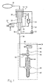
- FIG. 1 is a first embodiment of an inventive Injection device shown.
- a pressure accumulator 10 provides primary pressure. This will fed to a pressure booster 12 in its low pressure chamber 14.
- the pressure booster has 12 a high-pressure space 16 and a differential space 18 on.
- the low pressure chamber 14 is a throttle 20 and a Check valve 22 connected to the high pressure chamber 16.
- the Check valve 22 closes in the direction of the low pressure chamber 14.
- the low pressure chamber 14 is also a throttle 24 and a check valve 26 connected in parallel therewith connected to the differential space 18 of the pressure booster 12.
- the pressure booster piston 28 is by a spring 30 to Force applied for the purposes of the provision.
- the check valve 26 locks in the direction of the differential space 18.
- a valve device is used to control the pressure booster 12 32 provided which is connected to the Differential space 18 of the pressure booster 12 in connection stands.
- the other connection of the valve device 32 is with a return system 34 connected.
- the pressure booster piston 28 With the valve device closed 32, the pressure booster piston 28 is pressure-balanced, since in the differential space 18 via the throttle 24 in the low pressure chamber 14 prevails rail pressure.
- the Pressure booster is deactivated, meaning that it cannot find one Pressure increase instead. Consequently, an injection is with Rail printing possible.
- the pressure booster piston moves 28 according to the amount injected without pressure boosting downward.
- the pressure booster 12 works here like a flow limiter. In particular has the pressure booster piston 28 has a valve seat at its end 36, so that when the maximum stroke is reached, the feed line 38 closes to the injector 40.
- the injector 40 comprises an injection nozzle 42, the pressure chamber 44 with the inlet line 38, which is connected to the high-pressure chamber 16 of the pressure booster 12 is connected, is connected.
- the injector 40 is stroke-controlled, with a control valve 46 on the one hand with a return system 34 and on the other hand via an outlet throttle 48 with a control chamber 50 of the injection nozzle connected is.
- the control room 50 is also above a Inlet throttle 52 in connection with the supply line 38.
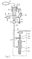
- Figure 2 shows a second embodiment of an inventive Injector.
- the differential space 18 of the pressure booster 12 with the high pressure chamber 16 of the pressure booster 12 connected The refilling of the high pressure room 16 thus takes place via this filling path.
- This too is with a throttle 56 and one towards the Differential space 18 provided check valve 58, these components being connected in series.
- FIG 3 is a third embodiment of an inventive Injection device shown. This corresponds largely the first embodiment shown in Figure 1 the invention.
- the sealing seat or sealing device 36 ( Figure 1) for closing the inlet line 38 is, however replaced by a slide valve 60 ( Figure 3), which the filling path 62 from a certain stroke of the pressure booster piston 28 closes.
- Figure 4 shows a fourth embodiment of the invention.
- a separate flow limiter 64 is provided in the connection of the low pressure chamber 14 with the high pressure chamber 18.
- a flow restrictor 66 in the connection between the high pressure chamber 16 of the pressure booster 12 and the injector 40.
- the flow restrictor in the connection between the low pressure chamber 14 and the high pressure chamber 16 of the pressure booster 12 is again a check valve 68 with the Pressure booster 64 connected in series for pressure transmission from the high pressure space 16 into the low pressure space 14 to avoid.
Landscapes
- Engineering & Computer Science (AREA)
- Chemical & Material Sciences (AREA)
- Combustion & Propulsion (AREA)
- Mechanical Engineering (AREA)
- General Engineering & Computer Science (AREA)
- Physics & Mathematics (AREA)
- Fluid Mechanics (AREA)
- Fuel-Injection Apparatus (AREA)
- Nozzles (AREA)
- Injection Moulding Of Plastics Or The Like (AREA)
- Jet Pumps And Other Pumps (AREA)
- Consolidation Of Soil By Introduction Of Solidifying Substances Into Soil (AREA)
Abstract
Description
Die Erfindung betrifft eine Einspritzeinrichtung mit einer Einspritzdüse, einem Druckverstärker zum Verstärken eines primären Druckes, einer ersten Ventileinrichtung zum Ansteuern des Druckverstärkers und einem Stellelement zum Betätigen der ersten Ventileinrichtung. Die Erfindung betrifft ferner ein Verfahren zum Einspritzen von Fluid, bei dem in einer ersten Phase eine Einspritzung mit niedrigem Druck erfolgt und in einer zweiten Phase eine Einspritzung mit hohem Druck erfolgt.The invention relates to an injection device with a Injector, a pressure booster to reinforce a primary pressure, a first valve device for actuation of the pressure booster and an actuator for actuation the first valve device. The invention relates a method for injecting fluid, in which in In a first phase, low-pressure injection takes place and in a second phase a high injection Printing takes place.
Eine gattungsgemäße Vorrichtung und ein gattungsgemäßes Verfahren sind bekannt. Eine Grundanforderung an ein solches System besteht darin, die Kraftstoffeinspritzung mit einem möglichst großen Einspritzdruck vorzunehmen. Ein hoher Einspritzdruck hat positive Einflüsse auf die Funktion eines Motors; zum Beispiel werden die Schadstoffemissionen und der Kraftstoffverbrauch herabgesetzt. Es kann allerdings zusätzlich erwünscht sein, mit demselben System eine Einspritzung mit niedrigerem Druck vorzunehmen. Eine solche Einspritzung mit niedrigem Druck kann beispielsweise für eine Voreinspritzung verwendet werden, die unter anderem der Geräuschminderung dient. Durch die Bereitstellung unterschiedlicher Drücke während eines Einspritzzyklus kann beispielsweise eine vorteilhafte "boot"-Form des Einspritzdruckverlaufes erzielt werden.A generic device and a generic method are known. A basic requirement for such System is fuel injection with one to make the greatest possible injection pressure. A high injection pressure has a positive influence on the function of a motor; for example the pollutant emissions and the Reduced fuel consumption. However, it can be additional an injection with the same system to carry out with lower pressure. Such an injection Low pressure can be used, for example, for a pre-injection used, among other things, the noise reduction serves. By providing different For example, pressures during an injection cycle an advantageous "boot" form of the injection pressure curve be achieved.
Zur Realisierung des hohen Einspritzdruckes ist ein Druckverstärker vorgesehen, welcher durch eine hydraulische Übersetzung einen primären, etwa von einem Druckspeicher zur Verfügung gestellten Druck in den erwünschten hohen Einspritzdruck umsetzt. Durch die geeignete Wahl der mit Kraft beaufschlagten Flächen und die Gegenkräfte elastischer Mittel kann auf diese Weise eine geeignete Druckverstärkung eingestellt werden.A pressure booster is used to implement the high injection pressure provided by hydraulic translation a primary, for example from a pressure accumulator to Provided pressure in the desired high injection pressure implements. By choosing the right one with strength acted surfaces and the counter forces of elastic means can provide a suitable pressure boost in this way can be set.
Eine gattungsgemäße Druckverstärkung ist insbesondere im Zusammenhang mit einem Common-Rail-System nützlich. Bei der Speichereinspritzung "Common-Rail" sind die primäre Druckerzeugung und die Einspritzung entkoppelt. Der Einspritzdruck wird von einer Hochdruckpumpe erzeugt und im "Rail" (Kraftstoffspeicher) für die Einspritzung bereitgestellt. Auf diese Weise läßt sich grundsätzlich ein günstiger Einspritzverlauf realisieren, da insbesondere Einspritzdruck und Einspritzmenge für jeden Betriebspunkt des Motors unabhängig voneinander festgelegt werden können. Allerdings ist der Druck im Common-Rail zur Zeit noch auf ca. 1600 bar begrenzt, so daß aus Emissionsgründen eine Erhöhung des Drukkes erwünscht ist. Ein Druckverstärker in Kombination mit einem Common-Rail-System könnte somit besonders gute Ergebnisse liefern. Allerdings müssen bei druckverstärkten Common-Rail-Systemen für die Wiederbefüllung der verschiedenen funktionellen Räume des Druckverstärkers zusätzliche Ventileinrichtungen vorgesehen werden. Gemäß dem Stand der Technik wird der gesamte Hochdruckraum im Injektor und im Druckverstärker entspannt, was zu hohen Entspannungsverlusten führt. A generic pressure boost is particularly related useful with a common rail system. In the Memory injection "common rail" are the primary pressure generation and decouples the injection. The injection pressure is generated by a high pressure pump and in the "rail" (fuel storage) provided for injection. To this In principle, a favorable injection course can be done realize, in particular injection pressure and injection quantity independent for each operating point of the engine can be determined from each other. However, the Pressure in the common rail is currently limited to approx. 1600 bar, so that for emission reasons an increase in pressure is desired. A pressure booster in combination with A common rail system could therefore give particularly good results deliver. However, with pressure-reinforced common rail systems for refilling the various functional spaces of the pressure booster additional valve devices be provided. According to the state of the art the entire high pressure space in the injector and in the Pressure booster relaxes, resulting in high relaxation losses leads.
In Figur 5 ist ein Common-Rail-System dargestellt, bei dem ein Injektor bzw. eine
Einspritzdüse 110 mit einem Druckverstärker 112 gekoppelt ist. Die Ansteuerung des
Druckverstärkers 112 erfolgt über ein 2/2-Ventil 114, das den Druck im Raum 134
steuert, so dass im Vergleich zur Ansteuerung mit einem 3/2-Ventil im
Druckverstärkerzulauf vergleichsweise geringe Entspannungsverluste vorliegen. Die
dargestellte hydraulische Schaltung weist einen Bypass-Pfad 116 auf, um wahlweise eine
Einspritzung mit Rail-Druck oder eine Einspritzung mit verstärktem Druck zu
ermöglichen. Die Aktivierung bzw. die Deaktivierung des Druckverstärkers 112 erfolgt
durch das Öffnen bzw. Schließen des Ventils 114. Allerdings ist bei diesem System zu
beachten, dass über den Bypass-Pfad 116 stets Rail-Druck zum Injektor 110 geleitet wird.
Ein Klemmen der Einspritzdüsennadel oder des Injektorventils würde folglich eine
Dauereinspritzung erzeugen, was schließlich zur Zerstörung des Motors führen kann. Es
ist daher erwünscht, ein System mit einer Eigensicherheit bereitzustellen, welches eine
konstruktiv festgelegte maximale Einspritzmenge aufweist, das heißt eine
Einspritzmenge, die im Schadensfall einer Systemkomponente nicht überschritten werden
kann.FIG. 5 shows a common rail system in which an injector or a
Aus der US 5,622,152 ist eine Einspritzeinrichtung bekannt, bei der eine Einspritzung mit niedrigem Druck erfolgt, indem Kraftstoff direkt aus dem Druckspeicher zum Einspritzventil geführt wird, und bei der eine Einspritzung mit hohem Druck erfolgt, indem Kraftstoff unter mittels Druckverstärker erhöhtem Druck dem Einspritzventil zugeführt wird.An injection device is known from US Pat. No. 5,622,152, in which an injection with low pressure is done by direct fuel from the accumulator to the Injection valve is guided, and in which an injection takes place at high pressure, by fuel under pressure increased by means of the pressure booster the injection valve is fed.
Der Vollständigkeit halber werden noch die anderen Komponenten des in Figur 5
dargestellten Systems beschrieben. Ein Ventil 118 ist zur Hubsteuerung über eine
Ablaufdrossel 120 mit einem Steuerraum 122 des Injektors 110 verbunden. Der
Steuerraum 122 steht ferner über eine
Zulaufdrossel 124 mit dem Fluidzufluß in Verbindung. Das Fluid wird ferner dem
Druckraum 126 der Einspritzdüse 110 zugeleitet. In der Fluidzuleitung 116 befindet sich
ein
Rückschlagventil 128, welches einen Fluidtransport nur in Richtung der Einspritzdüse
126 zulässt. Der Druckverstärker 112 hat einen Niederdruckraum 130, einen
Hochdruckraum 132 und einen Differenzraum 134. Der Differenzraum 134 ist über eine
Drossel 136 mit dem
welches einen Fluidtransport nur in Richtung der Einspritzdüse 126 zulässt. Der
Druckverstärker 112 hat einen Niederdruckraum 130, einen Hochdruckraum 132 und
einen Differenzraum 134. Der Differenzraum 134 ist über eine Drossel 136 mit dem
Druckspeicher ("Rail") 138 verbunden, während der Niederdruckraum 130 und der
Hochdruckraum 132 direkt bzw. über das Rückschlagventil 128 mit dem Druckspeicher
138 in Verbindung stehen. Der Druckspeicher 138 hat bei einem Vierzylindermotor
Anschlüsse zu vier Injektoren, denen er den Rail-Druck zur Verfügung stellt. Eine
Zuleitung zum Druckspeicher 138, in welcher ein Drucksensor und ein Regelkreis
vorgesehen ist, kommt von einem Kraftstofftank 140 über eine mengengeregelte
Hochdruckpumpe 142.For the sake of completeness, the other components of FIG
described system described. A
Durch die Erfindung wird zum einen in einfacher Weise eine Ansteuerung eines Druckverstärkers durch ein Ventil ermöglicht, wobei nur geringe Entspannungsverluste auftreten, und dies wird erfindungsmässig mit einer Durchflußmengenbegrenzung zur Einspritzdüse kombiniert. Somit ist also ausgeschlossen, dass ein Verklemmen der Düsennadel bzw. des Steuerventils der Einspritzdüse zu einer Dauereinspritzung und letztlich zu einer Zerstörung des Motors führen könnten.On the one hand, the invention enables control of a Pressure amplifier made possible by a valve, with only slight relaxation losses occur, and this is according to the invention with a flow rate limitation Injector combined. It is therefore impossible that the Nozzle needle or the control valve of the injection nozzle for a continuous injection and could ultimately lead to the destruction of the engine.
Der Druckverstärker weist einen Niederdruckraum, einen Hochdruckraum und einen Differenzraum auf, wobei die erste Ventileinrichtung mit einem ersten Anschluß mit dem Differenzraum verbunden ist, die erste Ventileinrichtung mit einem zweiten Anschluß mit einem Rücklaufsystem verbunden ist und die erste Ventileinrichtung in dem ersten Zustand geöffnet ist, so daß der Differenzraum mit dem Rücklaufsystem verbunden ist. Im geschlossenen Zustand des Ventils ist der Kolben des Druckverstärkers somit druckausgeglichen, da sich in dem Differenzraum der Rail-Druck einstellt. Es findet keine Druckverstärkung statt. Wird allerdings das Ventil geöffnet, so entlastet diese Maßnahme den Differenzraum. Folglich wird der Druckverstärker aktiviert, und es kann eine Einspritzung mit erhöhtem Druck erfolgen.The pressure booster has a low pressure chamber, a high pressure chamber and one Difference space, whereby the first valve device with a first connection is connected to the differential space, the first valve device connected to a return system with a second connection and the first valve device is in the first state is open so that the differential space with the return system connected is. When the valve is closed the piston of the pressure booster is therefore pressure balanced, since the rail pressure is established in the differential space. There is no pressure boost. However this valve relieves the pressure on the valve Differential chamber. So the pressure booster is activated and an injection with increased pressure can take place.
Es ist von Vorteil, wenn der Niederdruckraum des Druckverstärkers mit dem Differenzraum des Druckverstärkers über eine erste Drossel und eine zweite Ventileinrichtung verbunden ist, wobei die erste Drossel und die zweite Ventileinrichtung parallel angeordnet sind, die zweite Ventileinrichtung den Fluß eines Fluids von dem Differenzraum zu dem Niederdruckraum freigibt und die zweite Ventileinrichtung den Fluß eines Fluids von dem Niederdruckraum zu dem Differenzraum sperrt. Die zweite Ventileinrichtung ermöglicht somit, daß der Differenzraum bei geöffneter erster Ventileinrichtung drucklos wird, so daß eine Aktivierung des Druckverstärkers erfolgen kann. Die zweite Ventileinheit verhindert, daß sich im Differenzraum ein Überdruck gegenüber dem Niederdruckraum aufbauen kann. Über die Drossel wird der Differenzraum bei der Rückstellung des Druckverstärkers befüllt.It is advantageous if the low pressure chamber of the pressure booster with the differential space of the pressure booster over a first throttle and a second valve device connected is, wherein the first throttle and the second valve device are arranged in parallel, the second valve device the flow of a fluid from the differential space to the low pressure space releases and the second valve means the flow a fluid from the low pressure space to the differential space locks. The second valve device thus enables that the differential space when the first valve device is open is depressurized, so that an activation of the pressure booster can be done. The second valve unit prevents in the differential space an overpressure compared to the low pressure space can build up. About the throttle, the differential space at reset the pressure booster.
Vorzugsweise ist die zweite Ventileinrichtung ein Rückschlagventil. Ein solches ist geeignet, die beschriebenen Funktionen der zweiten Ventileinrichtung auszuführen. The second valve device is preferably a check valve. One such is suitable, the ones described Perform functions of the second valve device.
Vorzugsweise ist der Niederdruckraum des Druckverstärkers mit dem Hochdruckraum des Druckverstärkers über eine zweite Drossel und ein Rückschlagventil verbunden, wobei das Rückschlagventil den Fluß eines Fluids von dem Niederdruckraum zu dem Hochdruckraum freigibt und das Rückschlagventil den Fluß eines Fluids von dem Hochdruckraum zu dem Niederdruckraum sperrt. Das Rückschlagventil ist nützlich, damit der Druck aus dem Hochdruckraum sich nicht in Richtung des Niederdruckraumes abbaut. Die Drossel stellt sicher, daß die Verbindung einen hinreichend kleinen Durchflußquerschnitt aufweist, so daß sie nicht als Bypass für eine Einspritzung dienen kann. Durch diese Maßnahme wird bei einem unerwünschten, erhöhten Leckagestrom im Injektor, z.B. durch Nadelklemmen, eine Druckdifferenz zwischen dem Niederdruckraum und dem Hochdruckraum des Druckverstärkers erzeugt, wodurch ein Druckverstärkerkolben seinen Maximalhub einnimmt. Die Drossel kann auch durch eine entsprechend kleine Leitung oder einen entsprechend kleinen Öffnungsquerschnitt des Rückschlagventils gebildet werden. Grundsätzlich dient die Verbindung der Wiederbefüllung des Hochdruckraums des Druckverstärkers beim Rückstellen des Druckverstärkerkolbens.The low-pressure chamber of the pressure booster is preferably with the high pressure chamber of the pressure booster via a second Throttle and a check valve connected, the check valve the flow of a fluid from the low pressure space releases to the high pressure chamber and the check valve Flow of a fluid from the high pressure space to the low pressure space locks. The check valve is useful so that the Pressure from the high pressure room does not move towards the low pressure room degrades. The throttle ensures that the Connection a sufficiently small flow cross-section has so that it does not act as a bypass for an injection can serve. With this measure, an undesired, increased leakage current in the injector, e.g. by needle clamps, a pressure difference between the low pressure space and the high pressure chamber of the pressure booster generated, whereby a pressure booster piston takes its maximum stroke. The Throttle can also be through a correspondingly small line or a correspondingly small opening cross section of the Check valve are formed. Basically, the serves Connection of the refilling of the high pressure chamber of the pressure booster when resetting the pressure booster piston.
Ebenfalls kann vorgesehen sein, daß der Differenzraum des Druckverstärkers mit dem Hochdruckraum des Druckverstärkers über eine zweite Drossel und ein Rückschlagventil verbunden ist, wobei das Rückschlagventil den Fluß eines Fluids von dem Differenzraum zu dem Hochdruckraum freigibt und das Rückschlagventil den Fluß eines Fluids von dem Hochdruckraum zu dem Differenzraum sperrt. Die genannten Komponenten erfüllen somit denselben Zweck wie im Falle der Verbindung des Niederdruckraums mit dem Hochdruckraum. Dabei kann die zweite Drossel auch entfallen und der Differenzraum des Druckverstärkers mit dem Hochdruckraum über ein Rückschlagventil verbunden sein, da ein unerwünschter Leckagestrom im Injektor an der ersten Drossel zwischen Niederdruckraum und Differenzraum eine Druckdifferenz erzeugt.It can also be provided that the difference space of the Pressure booster with the high pressure chamber of the pressure booster connected via a second throttle and a check valve wherein the check valve is the flow of a fluid from releases the differential space to the high pressure space and that Check valve the flow of a fluid from the high pressure space locks to the difference space. Meet the components mentioned thus the same purpose as in the case of the connection of the Low pressure room with the high pressure room. The second Throttle also eliminated and the differential space of the pressure booster with the high pressure chamber via a check valve be connected because of an undesirable leakage current in the injector at the first throttle between the low pressure space and the differential space generates a pressure difference.
Besondere Vorzüge der Erfindung zeigen sich, wenn der Druckverstärker ab dem Erreichen eines bestimmten Hubs eine Strömungsverbindung vom Druckspeicher zur Einspritzdüse unterbricht. Hierdurch wird verhindert, daß, etwa bei einem Verklemmen der Einspritzdüse oder einem Verklemmen des Steuerventils der Einspritzdüse, eine Dauereinspritzung und somit eine Zerstörung des Motors stattfindet. Vorzugsweise weist der Druckverstärkerkolben eine Druckfläche auf, die auch nach Unterbrechung der Strömungsverbindung zum Injektor mit der Injektorzuleitung in Verbindung steht. Somit bleibt der Druckverstärkerkolben druckdifferenzgesteuert an seinem Endanschlag. Auf diese Weise wird der entsprechende Injektor im Schadensfall abgeschaltet.Particular advantages of the invention show up when the pressure booster a flow connection from reaching a certain stroke from the pressure accumulator to the injection nozzle. This prevents, for example, jamming the injector or a jamming of the control valve the injector, a continuous injection and thus the engine is destroyed. Preferably points the pressure booster piston has a pressure surface that also after interrupting the flow connection to the injector the injector supply line is connected. So the remains Pressure booster piston controlled by pressure difference on his End stop. In this way, the corresponding injector switched off in the event of damage.
Es ist vorteilhaft, wenn ein Verschließen der Zulaufleitung durch eine Dichtvorrichtung vorgesehen ist. Die beiden Komponenten der Dichtvorrichtung führen dann zum Verschließen der Zulaufleitung, wenn der Druckverstärkerkolben seinen maximalen Hub eingenommen hat.It is advantageous if the inlet line is closed is provided by a sealing device. The two components the sealing device then lead to closure the supply line when the pressure booster piston reaches its maximum Hub.
Es kann aber auch vorteilhaft sein, wenn ein Verschließen des Befüllungspfades durch eine Schieberdichtung vorgesehen ist. Diese Schieberdichtung kann vom Druckverstärkerkolben und der Führung des Druckverstärkerkolbens gebildet werden. Ein Verschließen der Zulaufleitung kann somit ab einem bestimmten Hub erfolgen, welcher davon abhängt, an welcher Stelle der Fluidzufluß am Hochdruckraum des Druckverstärkers ansetzt.But it can also be advantageous if a closure the filling path is provided by a slide seal is. This slide seal can come from the pressure booster piston and the guide of the pressure booster piston are formed. Closing the supply line can therefore start at a certain point Stroke, which depends on which Place the fluid flow at the high pressure chamber of the pressure booster attaches.
Vorzugsweise sind elastische Mittel zum Rückstellen des Druckverstärkerkolbens vorgesehen. Diese können wahlweise im Niederdruckraum, im Differenzraum oder im Hochdruckraum oder an einer sonstigen geeigneten Stelle angeordnet sein. Die elastischen Mittel können beispielsweise durch eine Feder im Niederdruckraum verwirklicht sein.Preferably elastic means for resetting the Booster piston provided. These can either be in Low pressure room, in the differential room or in the high pressure room or be arranged at another suitable location. The elastic means can for example by a spring in Low-pressure room can be realized.
Weiterhin kann es vorteilhaft sein, daß mindestens ein separater Durchflußbegrenzer vorgesehen ist. Gemäß bevorzugter Ausführungsformen der Erfindung wirkt der Druckverstärker zwar gleichzeitig als Durchflußbegrenzer. Es kann allerdings unter Umständen sinnvoll sein, einen separaten Durchflußbegrenzer zu verwenden. Dieser kann wahlweise etwa im Befüllungspfad des Hochdruckraums oder zwischen Druckverstärker und Injektor angeordnet sein.Furthermore, it can be advantageous for at least one separate one Flow limiter is provided. According to more preferred Embodiments of the invention act on the pressure booster at the same time as a flow limiter. However, it can Under certain circumstances it may be useful to have a separate flow limiter to use. This can optionally be in the filling path the high pressure chamber or between the pressure booster and the injector.
Es kann auch vorteilhaft sein, einen zweiteiligen Druckverstärkerkolben vorzusehen. Dabei kann die zweite Ventileinheit, welche parallel zur Drossel den Niederdruckraum des Druckverstärkers mit dem Differenzraum verbindet, entfallen, da durch die Trennung der Druckverstärkerkolben ein Überdruck im Differenzraum unterbunden wird.It may also be advantageous to have a two-part pressure booster piston provided. The second valve unit, which parallel to the throttle the low pressure chamber of the Pressure booster connects to the differential space, as an overpressure due to the separation of the pressure booster pistons is prevented in the difference space.
Die Erfindung baut nach Anspruch 17 auf dem gattungsgemäßen Verfahren dadurch auf, daß der hohe Druck unter Aktivierung eines Druckverstärkers erzeugt wird, indem eine mit einem Differenzraum des Druckverstärkers und einem Rücklaufsystem in Verbindung stehende Ventileinrichtung geöffnet wird und daß die Durchflußmenge des Fluids zu einer Einspritzdüse begrenzt wird. Es kann somit durch eine einfache Betätigung einer Ventileinrichtung unter Vermeidung hoher Entspannungsverluste eine Ansteuerung, das heißt eine Aktivierung bzw. eine Deaktivierung eines Druckverstärkers erfolgen. Die Durchflußmengenbegrenzung vermeidet eine Beschädigung des Motors, welche ansonsten aufgrund einer Dauereinspritzung beim Verklemmen der Düsennadel oder des Steuerventils der Einspritzdüse erfolgen könnte.The invention is based on the generic type according to claim 17 Process in that the high pressure under activation a pressure booster is generated by one with a Differential space of the pressure booster and a return system related valve device is opened and that limits the flow rate of the fluid to an injector becomes. It can thus be done by a simple operation a valve device while avoiding high relaxation losses a control, that is an activation or a pressure booster is deactivated. The Flow limitation prevents damage to the Motors, which are otherwise due to continuous injection when jamming the nozzle needle or the control valve Injector could be done.
Das Verfahren ist besonders vorteilhaft, wenn die maximale Einspritzmenge von dem Volumen eines Hochdruckraums des Druckverstärkers begrenzt wird. Der Druckverstärker wird also in vorteilhafter Weise gleichzeitig zu seinem primären Zweck - der Druckverstärkung - genutzt als auch, im Sinne der Eigensicherheit, zur Durchflußmengenbegrenzung.The method is particularly advantageous when the maximum Injection quantity from the volume of a high-pressure chamber Pressure booster is limited. So the pressure booster is advantageously at the same time as its primary Purpose - the pressure boosting - used as well, in the sense intrinsic safety, to limit the flow rate.
Es kann allerdings gelegentlich auch von Vorteil sein, wenn die maximale Einspritzmenge von einem separaten Durchflußmengenbegrenzer begrenzt wird. Diese Lösung, welche auch in Kombination mit einer Durchflußbegrenzung des Druckverstärkers vorgesehen sein kann, ist grundsätzlich komplizierter. Eine separate Durchflußbegrenzung kann allerdings im Hinblick auf die Auslegung des Druckverstärkers vorteilhaft sein.However, it can sometimes be an advantage if the maximum injection quantity from a separate flow limiter is limited. This solution, which also in Combination with a flow limitation of the pressure booster can be provided is fundamentally more complicated. A separate flow limitation can, however, be considered advantageous to the design of the pressure booster his.
Es ist vorteilhaft, wenn der Injektor hubgesteuert ist, wobei sogar denkbar ist, daß das Steuerventil des Injektors von demselben Stellelement, vorzugsweise einem Piezoaktor, angesteuert wird, wie die Ventileinrichtung, welche den Druckverstärker ansteuert. Als Stellelement kann neben einem Piezoaktor beispielsweise auch ein Magnetventil vorgesehen sein.It is advantageous if the injector is stroke-controlled, whereby it is even conceivable that the control valve of the injector from the same control element, preferably a piezo actuator, is controlled, such as the valve device, which the Activates pressure booster. As an actuator can next to a Piezo actuator, for example, also provided a solenoid valve his.
Der Erfindung liegt die Erkenntnis zugrunde, daß ein System mit einer hohen Eigensicherheit unter Verwendung einer Ansteuerung eines Druckverstärkers bereitgestellt werden kann, ohne daß große Entspannungsverluste auftreten. Der Druckverstärker kann somit wahlweise aktiviert werden, und es kann eine Einspritzverlaufsformung vorgenommen werden. Beispielsweise kann eine Voreinspritzung mit geringem Druck und eine Haupteinspritzung mit hohem Druck stattfinden. Es kann somit zum Beispiel eine vorteilhafte "boot"-Form des Einspritzdruckverlaufes erreicht werden.The invention is based on the knowledge that a system with high intrinsic safety using a control a pressure booster can be provided, without great relaxation losses. The pressure booster can thus be activated optionally and it can an injection course shaping can be made. For example can be a pre-injection with low pressure and a Main injection take place under high pressure. So it can for example an advantageous "boot" form of the injection pressure curve can be achieved.
Die Erfindung wird nun mit Bezug auf die Zeichnung anhand
spezieller Ausführungsformen beispielhaft erläutert.
In Figur 1 ist eine erste Ausführungsform einer erfindungsgemäßen
Einspritzeinrichtung dargestellt. Ein Druckspeicher
10 stellt einen primären Druck zur Verfügung. Dieser wird
einem Druckverstärker 12 in seinen Niederdruckraum 14 zugeleitet.
Neben dem Niederdruckraum 14 weist der Druckverstärker
12 einen Hochdruckraum 16 und einen Differenzraum 18
auf. Der Niederdruckraum 14 ist über eine Drossel 20 und ein
Rückschlagventil 22 mit dem Hochdruckraum 16 verbunden. Das
Rückschlagventil 22 sperrt in Richtung auf den Niederdruckraum
14. Der Niederdruckraum 14 ist ferner über eine Drossel
24 und ein damit parallel geschaltetes Rückschlagventil 26
mit dem Differenzraum 18 des Druckverstärkers 12 verbunden.
Der Druckverstärkerkolben 28 ist durch eine Feder 30 zum
Zwecke der Rückstellung mit Kraft beaufschlagt. Das Rückschlagventil
26 sperrt in Richtung auf den Differenzraum 18.In Figure 1 is a first embodiment of an inventive
Injection device shown. A
Zur Ansteuerung des Druckverstärkers 12 ist eine Ventileinrichtung
32 vorgesehen, welche über einen Anschluß mit dem
Differenzraum 18 des Druckverstärkers 12 in Verbindung
steht. Der andere Anschluß der Ventileinrichtung 32 ist mit
einem Rücklaufsystem 34 verbunden. Bei geschlossener Ventileinrichtung
32 ist der Druckverstärkerkolben 28 druckausgeglichen,
da sich im Differenzraum 18 über die Drossel 24 der
im Niederdruckraum 14 herrschende Rail-Druck einstellt. Der
Druckverstärker ist deaktiviert, das heißt es findet keine
Druckverstärkung statt. Folglich ist eine Einspritzung mit
Rail-Druck möglich. Dabei bewegt sich der Druckverstärkerkolben
28 entsprechend der eingespritzten Menge ohne Druckverstärkung
nach unten. Der Druckverstärker 12 arbeitet dabei
also wie ein Durchflußmengenbegrenzer. Insbesondere hat
der Druckverstärkerkolben 28 an seinem Ende einen Ventilsitz
36, so daß er beim Erreichen seines Maximalhubs die Zulaufleitung
38 zum Injektor 40 verschließt.A valve device is used to control the
Der Injektor 40 umfaßt eine Einspritzdüse 42, deren Druckraum
44 mit der Zulaufleitung 38, die am Hochdruckraum 16
des Druckverstärkers 12 angeschlossen ist, verbunden ist.
Der Injektor 40 ist hubgesteuert, wobei ein Steuerventil 46
einerseits mit einem Rücklaufsystem 34 und andererseits über
eine Ablaufdrossel 48 mit einem Steuerraum 50 der Einspritzdüse
verbunden ist. Der Steuerraum 50 steht ferner über eine
Zulaufdrossel 52 mit der Zuleitung 38 in Verbindung.The
Figur 2 zeigt eine zweite Ausführungsform einer erfindungsgemäßen
Einspritzeinrichtung. Hier ist im Unterschied zur
ersten Ausführungsform gemäß Figur 1 der Differenzraum 18
des Druckverstärkers 12 mit dem Hochdruckraum 16 des Druckverstärkers
12 verbunden. Die Wiederbefüllung des Hochdruckraums
16 erfolgt somit über diesen Befüllungspfad. Auch dieser
ist mit einer Drossel 56 und einem in Richtung auf den
Differenzraum 18 sperrenden Rückschlagventil 58 versehen,
wobei diese Komponenten hintereinander geschaltet sind.Figure 2 shows a second embodiment of an inventive
Injector. Here is different from
1, the
In Figur 3 ist eine dritte Ausführungsform einer erfindungsgemäßen
Einspritzeinrichtung dargestellt. Diese entspricht
weitgehend der in Figur 1 dargestellten ersten Ausführungsform
der Erfindung. Der Dichtsitz oder Dichtvorrichtung 36
(Figur 1) zum Verschließen der Zulaufleitung 38 ist allerdings
durch ein Schieberventil 60 (Figur 3) ersetzt, welches
den Befüllungspfad 62 ab einem bestimmten Hub des Druckverstärkerkolbens
28 verschließt.In Figure 3 is a third embodiment of an inventive
Injection device shown. This corresponds
largely the first embodiment shown in Figure 1
the invention. The sealing seat or sealing device 36
(Figure 1) for closing the
Figur 4 zeigt eine vierte Ausführungsform der Erfindung. In
der Verbindung des Niederdruckraums 14 mit dem Hochdruckraum
18 ist ein separater Durchflußbegrenzer 64 vorgesehen. Alternativ
(oder zusätzlich) ist ein Durchflußbegrenzer 66 in
der Verbindung zwischen dem Hochdruckraum 16 des Druckverstärkers
12 und dem Injektor 40 angeordnet. Im Falle der Anordnung
des Durchflußbegrenzers in der Verbindung zwischen
dem Niederdruckraum 14 und dem Hochdruckraum 16 des Druckverstärkers
12 ist wieder ein Rückschlagventil 68 mit dem
Druckverstärker 64 in Reihe geschaltet, um eine Druckübertragung
von dem Hochdruckraum 16 in den Niederdruckraum 14
zu vermeiden. Figure 4 shows a fourth embodiment of the invention. In
the connection of the
Die vorhergehende Beschreibung der Ausführungsbeispiele gemäß der vorliegenden Erfindung dient nur zu illustrativen Zwecken und nicht zum Zwecke der Beschränkung der Erfindung. Im Rahmen der Erfindung sind verschiedene Änderungen und Modifikationen möglich, ohne den Umfang der Ansprüche zu verlassen.The preceding description of the exemplary embodiments according to the present invention is for illustrative purposes only Purposes and not for the purpose of limiting the invention. Various changes and modifications are within the scope of the invention possible without the scope of the claims to leave.
Claims (12)
- Injection device having an injection nozzle (42), a pressure amplifier (12) which serves to amplify a primary pressure, the said pressure amplifier (12) and comprises a low-pressure chamber (14), a high-pressure chamber (16) connected to the injection nozzle (42), and a differential chamber (18), and having a first valve device (32) which is connected to the differential chamber (18), is actuated by an actuating element, and by which the connection of the differential chamber (18) to a return system (34) is controlled in order to activate the pressure amplifier (12), the first valve device (32) opening the connection of the differential chamber (18) to a return system (34) in a first state in such a way that the pressure amplifier (12) is activated, and closing the connection in a second state in such a way that the pressure amplifier (12) is deactivated, characterized in that the first of two connections of the valve device (32) is connected to the differential chamber (18) and the second connection is connected to the return system (34), and the low-pressure chamber (14) of the pressure amplifier (12) is connected to the differential chamber (18) of the pressure amplifier (12) via a first restrictor (24), and the low-pressure chamber (14) or the differential chamber (18) is connected to the high-pressure chamber (16) via a second restrictor (20, 56, 64) and a non-return valve (22, 58, 68), the non-return valve (22, 58, 68) releasing the flow of a fluid to the high-pressure chamber (16) and blocking the flow from the high-pressure chamber (16), and throughflow limitation of fluid out of the high-pressure chamber (16) to the injection nozzle (42) being provided, which is performed by the pressure amplifier (12).
- Injection device according to Claim 1, characterized in that the second valve device is a non-return valve (26).
- Injection device according to Claim 1 or 2, characterized in that, in order to limit the throughflow, the pressure amplifier (12) closes a feed line (38) out of the high-pressure chamber (16) to the injection nozzle (42) once a certain displacement has been reached.
- Injection device according to Claim 3, characterized in that a sealing seat (36) is provided in order to close the feed line (38).
- Injection device according to one of Claims 1 to 3, characterized in that a slide seal (60) is provided in order to close a filling path (62).
- Injection device according to one of the preceding claims, characterized in that at least one pressure-amplifier piston (28) controls a flow connection to an injector (40).
- Injection device according to Claim 6, characterized in that, in its end position, the pressure-amplifier piston (28) interrupts a flow connection to the injector (40).
- Injection device according to one of the preceding claims, characterized in that elastic means (30) are provided in order to restore the pressure-amplifier piston (28).
- Injection device according to one of the preceding claims, characterized in that the pressure-amplifier piston (28) has two parts.
- Injection device according to one of the preceding claims, characterized in that at least one separate throughflow limiter (64, 66) is provided.
- Method for injecting fluid, in which, in a first phase, injection takes place at low pressure and, in a second phase, injection takes place at high pressure, characterized in that the high pressure is produced by activating a pressure amplifier (12), by opening a valve device (32) which is connected to a differential chamber (18) of the pressure amplifier (12) and a return system (34), and in that the throughflow of a fluid to an injection nozzle (42) is limited, the maximum injection quantity being limited by the volume of a high-pressure chamber (16) of the pressure amplifier (12).
- Method according to Claim 12, characterized in that the maximum injection quantity is limited by a separate throughflow limiter (64, 66).
Applications Claiming Priority (3)
| Application Number | Priority Date | Filing Date | Title |
|---|---|---|---|
| DE10002273A DE10002273A1 (en) | 2000-01-20 | 2000-01-20 | Injection device and method for injecting fluid |
| DE10002273 | 2000-01-20 | ||
| PCT/DE2001/000098 WO2001052916A2 (en) | 2000-01-20 | 2001-01-12 | Injection device and method for injecting a fluid |
Publications (2)
| Publication Number | Publication Date |
|---|---|
| EP1252437A2 EP1252437A2 (en) | 2002-10-30 |
| EP1252437B1 true EP1252437B1 (en) | 2004-09-22 |
Family
ID=7628119
Family Applications (1)
| Application Number | Title | Priority Date | Filing Date |
|---|---|---|---|
| EP01909455A Expired - Lifetime EP1252437B1 (en) | 2000-01-20 | 2001-01-12 | Injection device and method for injecting a fluid |
Country Status (8)
| Country | Link |
|---|---|
| US (1) | US20030127539A1 (en) |
| EP (1) | EP1252437B1 (en) |
| JP (1) | JP2003520317A (en) |
| KR (1) | KR20020074481A (en) |
| AT (1) | ATE277279T1 (en) |
| DE (2) | DE10002273A1 (en) |
| TW (1) | TW558607B (en) |
| WO (1) | WO2001052916A2 (en) |
Families Citing this family (19)
| Publication number | Priority date | Publication date | Assignee | Title |
|---|---|---|---|---|
| DE10040526A1 (en) * | 2000-08-18 | 2002-03-14 | Bosch Gmbh Robert | Fuel injection system |
| DE10123911A1 (en) * | 2001-05-17 | 2002-11-28 | Bosch Gmbh Robert | Fuel injection device for internal combustion engine has transfer piston separating chamber connected to source from high pressure and return chambers |
| WO2002093001A1 (en) * | 2001-05-17 | 2002-11-21 | Robert Bosch Gmbh | Fuel injection device |
| DE10126686A1 (en) * | 2001-06-01 | 2002-12-19 | Bosch Gmbh Robert | Fuel injection system, for an IC motor, has a pressure amplifier with a sliding piston and controlled outflow cross section stages to set the fuel pressure according to the piston stroke and give a boot injection action |
| DE10149004C1 (en) * | 2001-10-04 | 2003-02-27 | Bosch Gmbh Robert | Fuel injection device for IC engine has compression piston displaced in compression space provided with annular shoulder defining second compression space |
| DE10148995A1 (en) * | 2001-10-04 | 2003-04-24 | Bosch Gmbh Robert | Fuel injection system, for direct fuel injection at an IC motor, has a pressure unit for each injection valve with a piston return spring within the primary zone so that the piston is unaffected by hydraulic oscillations |
| US6978943B2 (en) * | 2002-01-30 | 2005-12-27 | International Engine Intellectual Property Company, Llc | Governor plate apparatus |
| DE10213659A1 (en) | 2002-03-27 | 2003-10-16 | Bosch Gmbh Robert | Injection device and method for injecting fluid |
| GB0215488D0 (en) | 2002-07-04 | 2002-08-14 | Delphi Tech Inc | Fuel injection system |
| JP3931120B2 (en) * | 2002-07-10 | 2007-06-13 | ボッシュ株式会社 | Accumulated fuel injection system |
| DE10233088A1 (en) * | 2002-07-19 | 2004-01-29 | Robert Bosch Gmbh | Fuel injection device for an internal combustion engine comprises a mechanical locking arrangement provided on a pressure intensifier piston in a cut-off position |
| DE10249840A1 (en) * | 2002-10-25 | 2004-05-13 | Robert Bosch Gmbh | Fuel injection device for internal combustion engines |
| DE10260775A1 (en) * | 2002-12-23 | 2004-07-01 | Daimlerchrysler Ag | Fuel supply system for internal combustion engines with direct injection |
| JP3994990B2 (en) * | 2004-07-21 | 2007-10-24 | 株式会社豊田中央研究所 | Fuel injection device |
| DE102007002760A1 (en) * | 2007-01-18 | 2008-07-24 | Robert Bosch Gmbh | Fuel injector with integrated pressure booster |
| US7980224B2 (en) * | 2008-02-05 | 2011-07-19 | Caterpillar Inc. | Two wire intensified common rail fuel system |
| CN102392771A (en) * | 2011-04-07 | 2012-03-28 | 欧阳光耀 | High-pressure common-rail diesel engine rail-pressure reinforcement principle and device |
| US10550808B2 (en) * | 2014-12-19 | 2020-02-04 | Volvo Truck Corporation | Injection system of an internal combustion engine and automotive vehicle including such an injection system |
| CN110397533B (en) * | 2019-07-26 | 2021-03-23 | 重庆红江机械有限责任公司 | Diesel engine high-pressure fuel oil electric control booster pump |
Family Cites Families (6)
| Publication number | Priority date | Publication date | Assignee | Title |
|---|---|---|---|---|
| JPS5898654A (en) * | 1981-12-07 | 1983-06-11 | Nissan Motor Co Ltd | Fuel injecting apparatus |
| JP2885076B2 (en) * | 1994-07-08 | 1999-04-19 | 三菱自動車工業株式会社 | Accumulator type fuel injection device |
| US5537972A (en) * | 1994-07-28 | 1996-07-23 | Servojet Electronics Systems | Fuel injection system having a pressure intensifier incorporating an overtravel safety feature |
| DE19636088C2 (en) * | 1996-09-05 | 2003-02-06 | Avl Verbrennungskraft Messtech | Process for direct fuel injection control |
| DE19647304C1 (en) * | 1996-11-15 | 1998-01-22 | Daimler Benz Ag | Fuel injector for internal combustion engine |
| US5852997A (en) * | 1997-05-20 | 1998-12-29 | Stanadyne Automotive Corp. | Common rail injector |
-
2000
- 2000-01-20 DE DE10002273A patent/DE10002273A1/en not_active Ceased
-
2001
- 2001-01-12 JP JP2001552963A patent/JP2003520317A/en active Pending
- 2001-01-12 KR KR1020027009284A patent/KR20020074481A/en not_active Application Discontinuation
- 2001-01-12 WO PCT/DE2001/000098 patent/WO2001052916A2/en not_active Application Discontinuation
- 2001-01-12 US US10/181,481 patent/US20030127539A1/en not_active Abandoned
- 2001-01-12 DE DE50103747T patent/DE50103747D1/en not_active Expired - Fee Related
- 2001-01-12 EP EP01909455A patent/EP1252437B1/en not_active Expired - Lifetime
- 2001-01-12 AT AT01909455T patent/ATE277279T1/en not_active IP Right Cessation
- 2001-01-17 TW TW090101010A patent/TW558607B/en active
Also Published As
| Publication number | Publication date |
|---|---|
| EP1252437A2 (en) | 2002-10-30 |
| US20030127539A1 (en) | 2003-07-10 |
| TW558607B (en) | 2003-10-21 |
| JP2003520317A (en) | 2003-07-02 |
| DE10002273A1 (en) | 2001-08-02 |
| WO2001052916A2 (en) | 2001-07-26 |
| ATE277279T1 (en) | 2004-10-15 |
| KR20020074481A (en) | 2002-09-30 |
| WO2001052916A3 (en) | 2002-02-14 |
| DE50103747D1 (en) | 2004-10-28 |
Similar Documents
| Publication | Publication Date | Title |
|---|---|---|
| EP1252437B1 (en) | Injection device and method for injecting a fluid | |
| EP1636484B1 (en) | Injector for internal combustion engines | |
| EP1125046B1 (en) | Fuel injection system for an internal combustion engine with a pressure amplifier | |
| EP1598551B1 (en) | Fuel injection device | |
| DE19742320A1 (en) | Fuel injector | |
| DE2742466A1 (en) | PUMP NOZZLE FOR AIR-COMPRESSING INJECTION COMBUSTION MACHINES | |
| WO2004003374A1 (en) | Common rail injection system comprising a variable injector and booster device | |
| EP1520099B1 (en) | Boosted fuel injector with rapid pressure reduction at end of injection | |
| AT503660B1 (en) | DEVICE FOR INJECTING FUEL IN THE COMBUSTION ENGINE OF AN INTERNAL COMBUSTION ENGINE | |
| DE112006002672T5 (en) | A fuel injection system having a flow control valve separate from a fuel injector | |
| DE19919432C2 (en) | Common rail injector | |
| DE102004022267A1 (en) | Method and device for shaping the injection pressure at a fuel injector | |
| DE19921878A1 (en) | Fuel injection system for IC engine uses fuel injector with magnetically-operated injection valve and independent magnetic valve controlling pressure control valve for fuel feeds to and from injector | |
| EP1144859B1 (en) | Injection device and method for injection of fluids | |
| EP1252436B1 (en) | Injection device and method for injecting a fluid | |
| DE3009750C2 (en) | Fuel injection device for internal combustion engines | |
| EP1283954A1 (en) | Fuel injection system for an internal combustion engine | |
| EP1907686B1 (en) | Fuel injector | |
| WO2005014997A1 (en) | Fuel injection device for a combustion engine | |
| DE102005058079A1 (en) | Fuel injector for internal combustion engine, has valve arrangement with switching condition, in which arrangement hydraulically couples reset path with high pressure system and couples operating path with low pressure system | |
| DE102007034319A1 (en) | injector | |
| DE102006013704A1 (en) | Fuel injector, e.g. for a motor vehicle, has an injector body, a jet body and an actuator for operating a needle-shaped injection valve element | |
| WO2005059350A1 (en) | Injection nozzle | |
| WO2002093000A1 (en) | Fuel injection system | |
| DE2203508A1 (en) | ELECTROMAGNETICALLY CONTROLLED FUEL INJECTION DEVICE FOR COMBUSTION MACHINERY |
Legal Events
| Date | Code | Title | Description |
|---|---|---|---|
| PUAI | Public reference made under article 153(3) epc to a published international application that has entered the european phase |
Free format text: ORIGINAL CODE: 0009012 |
|
| 17P | Request for examination filed |
Effective date: 20020820 |
|
| AK | Designated contracting states |
Kind code of ref document: A2 Designated state(s): AT BE CH CY DE DK ES FI FR GB GR IE IT LI LU MC NL PT SE TR |
|
| 17Q | First examination report despatched |
Effective date: 20021129 |
|
| GRAP | Despatch of communication of intention to grant a patent |
Free format text: ORIGINAL CODE: EPIDOSNIGR1 |
|
| GRAS | Grant fee paid |
Free format text: ORIGINAL CODE: EPIDOSNIGR3 |
|
| GRAA | (expected) grant |
Free format text: ORIGINAL CODE: 0009210 |
|
| AK | Designated contracting states |
Kind code of ref document: B1 Designated state(s): AT BE CH CY DE DK ES FI FR GB GR IE IT LI LU MC NL PT SE TR |
|
| PG25 | Lapsed in a contracting state [announced via postgrant information from national office to epo] |
Ref country code: TR Free format text: LAPSE BECAUSE OF FAILURE TO SUBMIT A TRANSLATION OF THE DESCRIPTION OR TO PAY THE FEE WITHIN THE PRESCRIBED TIME-LIMIT Effective date: 20040922 Ref country code: IE Free format text: LAPSE BECAUSE OF FAILURE TO SUBMIT A TRANSLATION OF THE DESCRIPTION OR TO PAY THE FEE WITHIN THE PRESCRIBED TIME-LIMIT Effective date: 20040922 Ref country code: FI Free format text: LAPSE BECAUSE OF FAILURE TO SUBMIT A TRANSLATION OF THE DESCRIPTION OR TO PAY THE FEE WITHIN THE PRESCRIBED TIME-LIMIT Effective date: 20040922 Ref country code: NL Free format text: LAPSE BECAUSE OF FAILURE TO SUBMIT A TRANSLATION OF THE DESCRIPTION OR TO PAY THE FEE WITHIN THE PRESCRIBED TIME-LIMIT Effective date: 20040922 |
|
| REG | Reference to a national code |
Ref country code: GB Ref legal event code: FG4D Free format text: NOT ENGLISH |
|
| REG | Reference to a national code |
Ref country code: CH Ref legal event code: EP |
|
| REG | Reference to a national code |
Ref country code: IE Ref legal event code: FG4D Free format text: GERMAN |
|
| REF | Corresponds to: |
Ref document number: 50103747 Country of ref document: DE Date of ref document: 20041028 Kind code of ref document: P |
|
| PG25 | Lapsed in a contracting state [announced via postgrant information from national office to epo] |
Ref country code: SE Free format text: LAPSE BECAUSE OF FAILURE TO SUBMIT A TRANSLATION OF THE DESCRIPTION OR TO PAY THE FEE WITHIN THE PRESCRIBED TIME-LIMIT Effective date: 20041222 Ref country code: GR Free format text: LAPSE BECAUSE OF FAILURE TO SUBMIT A TRANSLATION OF THE DESCRIPTION OR TO PAY THE FEE WITHIN THE PRESCRIBED TIME-LIMIT Effective date: 20041222 Ref country code: DK Free format text: LAPSE BECAUSE OF FAILURE TO SUBMIT A TRANSLATION OF THE DESCRIPTION OR TO PAY THE FEE WITHIN THE PRESCRIBED TIME-LIMIT Effective date: 20041222 |
|
| PG25 | Lapsed in a contracting state [announced via postgrant information from national office to epo] |
Ref country code: ES Free format text: LAPSE BECAUSE OF FAILURE TO SUBMIT A TRANSLATION OF THE DESCRIPTION OR TO PAY THE FEE WITHIN THE PRESCRIBED TIME-LIMIT Effective date: 20050102 |
|
| PG25 | Lapsed in a contracting state [announced via postgrant information from national office to epo] |
Ref country code: CY Free format text: LAPSE BECAUSE OF FAILURE TO SUBMIT A TRANSLATION OF THE DESCRIPTION OR TO PAY THE FEE WITHIN THE PRESCRIBED TIME-LIMIT Effective date: 20050112 Ref country code: LU Free format text: LAPSE BECAUSE OF NON-PAYMENT OF DUE FEES Effective date: 20050112 |
|
| PG25 | Lapsed in a contracting state [announced via postgrant information from national office to epo] |
Ref country code: LI Free format text: LAPSE BECAUSE OF NON-PAYMENT OF DUE FEES Effective date: 20050131 Ref country code: AT Free format text: LAPSE BECAUSE OF NON-PAYMENT OF DUE FEES Effective date: 20050131 Ref country code: CH Free format text: LAPSE BECAUSE OF NON-PAYMENT OF DUE FEES Effective date: 20050131 Ref country code: MC Free format text: LAPSE BECAUSE OF NON-PAYMENT OF DUE FEES Effective date: 20050131 Ref country code: BE Free format text: LAPSE BECAUSE OF NON-PAYMENT OF DUE FEES Effective date: 20050131 |
|
| GBT | Gb: translation of ep patent filed (gb section 77(6)(a)/1977) |
Effective date: 20050116 |
|
| NLV1 | Nl: lapsed or annulled due to failure to fulfill the requirements of art. 29p and 29m of the patents act | ||
| REG | Reference to a national code |
Ref country code: IE Ref legal event code: FD4D |
|
| PLBE | No opposition filed within time limit |
Free format text: ORIGINAL CODE: 0009261 |
|
| STAA | Information on the status of an ep patent application or granted ep patent |
Free format text: STATUS: NO OPPOSITION FILED WITHIN TIME LIMIT |
|
| BERE | Be: lapsed |
Owner name: ROBERT BOSCH G.M.B.H. Effective date: 20050131 |
|
| ET | Fr: translation filed | ||
| 26N | No opposition filed |
Effective date: 20050623 |
|
| REG | Reference to a national code |
Ref country code: CH Ref legal event code: PL |
|
| PGFP | Annual fee paid to national office [announced via postgrant information from national office to epo] |
Ref country code: GB Payment date: 20070123 Year of fee payment: 7 |
|
| BERE | Be: lapsed |
Owner name: ROBERT *BOSCH G.M.B.H. Effective date: 20050131 |
|
| PG25 | Lapsed in a contracting state [announced via postgrant information from national office to epo] |
Ref country code: PT Free format text: LAPSE BECAUSE OF NON-PAYMENT OF DUE FEES Effective date: 20050222 |
|
| PGFP | Annual fee paid to national office [announced via postgrant information from national office to epo] |
Ref country code: IT Payment date: 20070504 Year of fee payment: 7 |
|
| GBPC | Gb: european patent ceased through non-payment of renewal fee |
Effective date: 20080112 |
|
| PG25 | Lapsed in a contracting state [announced via postgrant information from national office to epo] |
Ref country code: GB Free format text: LAPSE BECAUSE OF NON-PAYMENT OF DUE FEES Effective date: 20080112 |
|
| PG25 | Lapsed in a contracting state [announced via postgrant information from national office to epo] |
Ref country code: IT Free format text: LAPSE BECAUSE OF NON-PAYMENT OF DUE FEES Effective date: 20080112 |
|
| PGFP | Annual fee paid to national office [announced via postgrant information from national office to epo] |
Ref country code: DE Payment date: 20090327 Year of fee payment: 9 |
|
| PGFP | Annual fee paid to national office [announced via postgrant information from national office to epo] |
Ref country code: FR Payment date: 20090120 Year of fee payment: 9 |
|
| REG | Reference to a national code |
Ref country code: FR Ref legal event code: ST Effective date: 20100930 |
|
| PG25 | Lapsed in a contracting state [announced via postgrant information from national office to epo] |
Ref country code: FR Free format text: LAPSE BECAUSE OF NON-PAYMENT OF DUE FEES Effective date: 20100201 |
|
| PG25 | Lapsed in a contracting state [announced via postgrant information from national office to epo] |
Ref country code: DE Free format text: LAPSE BECAUSE OF NON-PAYMENT OF DUE FEES Effective date: 20100803 |