EP1251604A2 - Bürsten für einen Kommutatormotor - Google Patents
Bürsten für einen Kommutatormotor Download PDFInfo
- Publication number
- EP1251604A2 EP1251604A2 EP02008757A EP02008757A EP1251604A2 EP 1251604 A2 EP1251604 A2 EP 1251604A2 EP 02008757 A EP02008757 A EP 02008757A EP 02008757 A EP02008757 A EP 02008757A EP 1251604 A2 EP1251604 A2 EP 1251604A2
- Authority
- EP
- European Patent Office
- Prior art keywords
- brush
- commutator
- motor
- contact
- accommodating
- Prior art date
- Legal status (The legal status is an assumption and is not a legal conclusion. Google has not performed a legal analysis and makes no representation as to the accuracy of the status listed.)
- Withdrawn
Links
Images


Classifications
-
- H—ELECTRICITY
- H02—GENERATION; CONVERSION OR DISTRIBUTION OF ELECTRIC POWER
- H02K—DYNAMO-ELECTRIC MACHINES
- H02K5/00—Casings; Enclosures; Supports
- H02K5/04—Casings or enclosures characterised by the shape, form or construction thereof
- H02K5/14—Means for supporting or protecting brushes or brush holders
-
- H—ELECTRICITY
- H02—GENERATION; CONVERSION OR DISTRIBUTION OF ELECTRIC POWER
- H02K—DYNAMO-ELECTRIC MACHINES
- H02K7/00—Arrangements for handling mechanical energy structurally associated with dynamo-electric machines, e.g. structural association with mechanical driving motors or auxiliary dynamo-electric machines
- H02K7/10—Structural association with clutches, brakes, gears, pulleys or mechanical starters
- H02K7/116—Structural association with clutches, brakes, gears, pulleys or mechanical starters with gears
- H02K7/1163—Structural association with clutches, brakes, gears, pulleys or mechanical starters with gears where at least two gears have non-parallel axes without having orbital motion
- H02K7/1166—Structural association with clutches, brakes, gears, pulleys or mechanical starters with gears where at least two gears have non-parallel axes without having orbital motion comprising worm and worm-wheel
-
- H—ELECTRICITY
- H01—ELECTRIC ELEMENTS
- H01R—ELECTRICALLY-CONDUCTIVE CONNECTIONS; STRUCTURAL ASSOCIATIONS OF A PLURALITY OF MUTUALLY-INSULATED ELECTRICAL CONNECTING ELEMENTS; COUPLING DEVICES; CURRENT COLLECTORS
- H01R39/00—Rotary current collectors, distributors or interrupters
- H01R39/02—Details for dynamo electric machines
- H01R39/38—Brush holders
- H01R39/41—Brush holders cartridge type
-
- H—ELECTRICITY
- H02—GENERATION; CONVERSION OR DISTRIBUTION OF ELECTRIC POWER
- H02K—DYNAMO-ELECTRIC MACHINES
- H02K11/00—Structural association of dynamo-electric machines with electric components or with devices for shielding, monitoring or protection
- H02K11/30—Structural association with control circuits or drive circuits
- H02K11/38—Control circuits or drive circuits associated with geared commutator motors of the worm-and-wheel type
-
- H—ELECTRICITY
- H02—GENERATION; CONVERSION OR DISTRIBUTION OF ELECTRIC POWER
- H02K—DYNAMO-ELECTRIC MACHINES
- H02K5/00—Casings; Enclosures; Supports
- H02K5/04—Casings or enclosures characterised by the shape, form or construction thereof
-
- H—ELECTRICITY
- H02—GENERATION; CONVERSION OR DISTRIBUTION OF ELECTRIC POWER
- H02K—DYNAMO-ELECTRIC MACHINES
- H02K5/00—Casings; Enclosures; Supports
- H02K5/04—Casings or enclosures characterised by the shape, form or construction thereof
- H02K5/14—Means for supporting or protecting brushes or brush holders
- H02K5/143—Means for supporting or protecting brushes or brush holders for cooperation with commutators
- H02K5/148—Slidably supported brushes
-
- H—ELECTRICITY
- H01—ELECTRIC ELEMENTS
- H01R—ELECTRICALLY-CONDUCTIVE CONNECTIONS; STRUCTURAL ASSOCIATIONS OF A PLURALITY OF MUTUALLY-INSULATED ELECTRICAL CONNECTING ELEMENTS; COUPLING DEVICES; CURRENT COLLECTORS
- H01R39/00—Rotary current collectors, distributors or interrupters
- H01R39/02—Details for dynamo electric machines
- H01R39/38—Brush holders
- H01R39/385—Means for mechanical fixation of the brush holder
-
- H—ELECTRICITY
- H02—GENERATION; CONVERSION OR DISTRIBUTION OF ELECTRIC POWER
- H02K—DYNAMO-ELECTRIC MACHINES
- H02K11/00—Structural association of dynamo-electric machines with electric components or with devices for shielding, monitoring or protection
-
- H—ELECTRICITY
- H02—GENERATION; CONVERSION OR DISTRIBUTION OF ELECTRIC POWER
- H02K—DYNAMO-ELECTRIC MACHINES
- H02K2205/00—Specific aspects not provided for in the other groups of this subclass relating to casings, enclosures, supports
- H02K2205/06—Machines characterised by means for keeping the brushes in a retracted position during assembly
-
- H—ELECTRICITY
- H02—GENERATION; CONVERSION OR DISTRIBUTION OF ELECTRIC POWER
- H02K—DYNAMO-ELECTRIC MACHINES
- H02K5/00—Casings; Enclosures; Supports
- H02K5/04—Casings or enclosures characterised by the shape, form or construction thereof
- H02K5/16—Means for supporting bearings, e.g. insulating supports or means for fitting bearings in the bearing-shields
- H02K5/167—Means for supporting bearings, e.g. insulating supports or means for fitting bearings in the bearing-shields using sliding-contact or spherical cap bearings
- H02K5/1672—Means for supporting bearings, e.g. insulating supports or means for fitting bearings in the bearing-shields using sliding-contact or spherical cap bearings radially supporting the rotary shaft at both ends of the rotor
Definitions
- the present invention relates to a motor and a brush device used in, for example, a sun roof drive unit in motor vehicles.
- the motor and the brush device of this kind are known to have a construction in which a brush holder has its base end portion mounted to a holder base provided separately from a case and its front end portion attached with a brush. The brush is pressed against a commutator by the brush holder so that the brush is electrically connectable to the commutator.
- the present invention provides a small motor which comprises: a motor case accommodating an armature, the armature being adapted to rotate when energized; a rotatable reduction mechanism receiving the rotation of the armature; an output shaft coupled to the reduction mechanism for rotation; a gear case connected to the motor case to rotatably support the output shaft; a brush electrically connectable to a commutator provided to the armature; a brush spring for pressing the brush against the commutator; and a brush holder installed in the gear case and slidably holding the brush; wherein the brush holder has a fixing portion and a brush accommodating portion integrally formed therewith, the fixing portion being secured to the gear case, the brush accommodating portion slidably holding the brush; wherein the gear case is integrally formed with a reduction mechanism accommodating portion for accommodating the reduction mechanism and with a brush holder mounting portion in which the brush holder can be installed in a direction of an axis of the output shaft.
- the present invention provides a motor with the construction of the first aspect wherein the brush has a sliding portion and a tapered surface, the sliding portion being formed at almost a central part of the brush and protruding from a brush body to come into sliding contact with the commutator, the tapered surface adjoining the sliding portion and being arranged in a tapered configuration and adapted to contact the commutator and thereby increase an area of the brush in contact with the commutator as the wear of the sliding portion proceeds.
- the present invention provides a motor with the construction of the first or second aspect wherein a pair of the brush and the brush accommodating portion has a temporary locking means which, when inserting the commutator, temporarily locks the brush at a predetermined position so that the commutator can be inserted and which, after the commutator has been inserted, unlocks the brush allowing the brush to come into electrical contact with the commutator.
- the present invention provides a motor with the construction of the third aspect wherein the temporary locking means comprises a locking portion formed in the brush and a brush locking tongue piece formed in a part of the brush accommodating portion, the brush locking tongue piece being adapted to engage the locking portion of the brush when the commutator is inserted and, after the commutator has been inserted, to disengage from the locking portion.
- the temporary locking means comprises a locking portion formed in the brush and a brush locking tongue piece formed in a part of the brush accommodating portion, the brush locking tongue piece being adapted to engage the locking portion of the brush when the commutator is inserted and, after the commutator has been inserted, to disengage from the locking portion.
- the present invention provides a brush device which comprises: a brush electrically connectable to a commutator provided to an armature of a motor; and a brush holder secured to a case of the motor to hold the brush in such a way that the brush can be brought into sliding contact with the commutator; wherein the brush is formed with a sliding portion and a tapered surface, the sliding portion protruding from a brush body to come into sliding contact with the commutator, the tapered surface adjoining the sliding portion and being arranged in a tapered configuration and adapted to contact the commutator and thereby increase an area of the brush in contact with the commutator as the wear of the sliding portion proceeds.
- the present invention provides a brush device with the construction of the fifth aspect wherein the tapered surface of the brush comprises first and second tapered surfaces arranged one on each side of the sliding portion formed at almost a center of the brush with respect to a direction of rotation of the commutator.
- the present invention provides a brush device with the construction of the fifth or sixth aspect wherein the sliding portion of the brush has a curved surface.
- the present invention provides a brush device with the construction of the fifth, sixth or seventh aspect wherein a pair of the brush and the brush accommodating portion has a temporary locking means which, when inserting the commutator, temporarily locks the brush at a predetermined position so that the commutator can be inserted and which, after the commutator has been inserted, unlocks the brush allowing the brush to come into electrical contact with the commutator.
- the present invention provides a brush device with the construction of the eighth aspect wherein the temporary locking means comprises a locking portion formed in the brush and a brush locking tongue piece formed in a part of the brush accommodating portion, the brush locking tongue piece being adapted to engage the locking portion of the brush when the commutator is inserted and, after the commutator has been inserted, to disengage from the locking portion.
- the temporary locking means comprises a locking portion formed in the brush and a brush locking tongue piece formed in a part of the brush accommodating portion, the brush locking tongue piece being adapted to engage the locking portion of the brush when the commutator is inserted and, after the commutator has been inserted, to disengage from the locking portion.
- the brush holder having a brush accommodating portion for slidably holding the brush is installed in a brush holder mounting portion of the gear case in a direction of an axis of the output shaft to securely fix the fixing portion of the brush holder to the gear case. Therefore, the brush holder does not require the holder base and can be mounted directly to the gear case.
- Fig. 1 is a plan view showing an inner construction of a gear case of a motor in one embodiment of the motor and brush device according to the present invention.
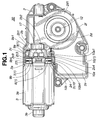
- Fig. 2 is an external perspective view of the motor of Fig. 1.
- Fig. 3 is an external perspective view showing a mounting position of the brush device in the motor of Fig. 1.
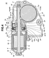
- Fig. 4 is a transverse cross section of the motor of Fig. 1.
- Fig. 5 is an enlarged view of the brush device and its associated parts in the motor of Fig. 4.
- Fig. 6 is a vertical cross section of a wheel gear and its associated parts in the motor of Fig. 1.
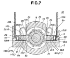
- Fig. 7 is a vertical cross section showing positions of the brushes when a commutator is installed in the motor of Fig. 1.
- Fig. 8 is a vertical cross section showing positions of the brushes when a commutator is installed in the motor of Fig. 1.
- Fig. 9 is an external perspective view of a single brush used in the motor of Fig. 1.
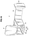
- Fig. 10 is an external perspective view of a single first brush holder in the motor of Fig. 1 as seen diagonally from above.
- Fig. 11 is an external perspective view of the single first brush holder in the motor of Fig. 1 as seen diagonally from below.
- Fig. 12 is an external perspective view, as seen diagonally from above, of the single first brush holder in the motor of Fig. 1 which holds a first brush.
- Fig. 13 is an external perspective view, as seen diagonally from below, of the single first brush holder in the motor of Fig. 1 which holds a first brush.
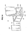
- Fig. 14 is an external perspective view of a single second brush holder in the motor of Fig. 1 as seen diagonally from above.
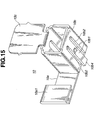
- Fig. 15 is an external perspective view of the single second brush holder in the motor of Fig. 1 as seen diagonally from below.
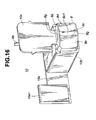
- Fig. 16 is an external perspective view, as seen diagonally from above, of the single second brush holder in the motor of Fig. 1 which holds a first brush.
- Fig. 17 is an external perspective view, as seen diagonally from below, of the single second brush holder in the motor of Fig. 1 which holds a first brush.
- Fig. 1 through Fig. 17 illustrate one embodiment of the motor and brush device according to the present invention.
- a motor 30 comprises mainly a gear case 2, a motor case 3, first and second magnets 4, 5, an armature 6, a wheel gear 11, an output shaft 12, and a brush device 1.
- the brush device 1 includes first and second brushes 7, 8 and first and second brush holders 9, 10.
- the armature 6 includes an armature shaft 13, an armature core 14, a commutator 15 and an armature coil 16.
- the gear case 2 has a flange portion 2a, an armature shaft accommodating portion 2b, a brush holder mounting portion 2c, a wheel gear accommodating portion 2d, a connector accommodating portion 2e, and a reduction mechanism accommodating portion 2f, all formed integral as one piece.
- the flange portion 2a is secured to an open end of the motor case 3 with screws 17.
- the armature shaft accommodating portion 2b is formed cylindrical, extending from a central part of the flange portion 2a toward the end of the gear case 2. As shown in Fig. 4, the armature shaft 13 of the armature 6 is inserted into the armature shaft accommodating portion 2b. In the armature shaft accommodating portion 2b, a first bearing 18 is arranged in the end portion of the gear case 2 and a second bearing 19 is arranged on the motor case side.
- the armature shaft accommodating portion 2b is formed with first and second rectangular magnetic force linking holes 2b1, 2b2 at positions corresponding to a sensor magnet 22 mounted on the armature shaft 13.
- the brush holder mounting portion 2c is arranged on the flange portion 2a side of the armature shaft accommodating portion 2b.
- the brush holder mounting portion 2c is formed with a pair of first and second brush holder insertion holes 2c1, 2c2 through which the first and second brush holders 9, 10 are inserted.
- the first and second brush holder insertion holes 2c1, 2c2 are formed rectangular and extend through the armature shaft accommodating portion 2b.
- the brush holder mounting portion 2c is formed with a pair of first and second fixing portions 2c3, 2c4 to which first and second fixing pieces 9a, 10a formed on the first and second brush holders 9, 10 are secured.
- the first and second fixing portions 2c3, 2c4 comprise plate portions 2c5, 2c6 and notches 2c7, 2c8, as shown in Fig. 3.
- the brush holder mounting portion 2c is formed with first and second protrusion insertion grooves 2c9, 2c10 in which a pair of protrusions 50a, 50b, formed on a brush unlocking jig 50 and arranged at positions corresponding to the first and second brush holder insertion holes 2c1, 2c2, are inserted.
- the wheel gear accommodating portion 2d is formed cylindrical and communicates with the interior of the armature shaft accommodating portion 2b.
- the wheel gear accommodating portion 2d accommodates the wheel gear 11 therein and is covered with a wheel gear cover 2d1 from outside.
- Formed at a central part of the wheel gear accommodating portion 2d is a shaft support portion 2d2 fixedly attached with a third bearing 20, as shown in Fig. 6.
- the third bearing 20 rotatably supports an output shaft 12 formed integral with a rotating central portion of the wheel gear 11.
- the output shaft 12 is coupled, for example, to a sun roof drive unit.
- the connector accommodating portion 2e is located by the side of the wheel gear accommodating portion 2d.
- a connector not shown is installed in the connector accommodating portion 2e. Terminals of the connector are electrically connected to a control circuit on a printed circuit board not shown which is accommodated in the reduction mechanism accommodating portion 2f.
- the reduction mechanism accommodating portion 2f that accommodates the printed circuit board is covered with a gear case cover not shown.
- First and second magnets 4, 5 are mounted on the inner side of a motor case body 3a of the motor case 3.
- An end cover 3b is attached to an end of the motor case body 3a on the closed side.
- the end cover 3b has a fourth bearing 21.
- the armature 6 is rotatably supported by the first and second magnets 4, 5 in a noncontact manner and by the first, second and fourth bearings 18, 19, 21.
- the armature 6 has an armature core 14, a commutator 15 and a sensor magnet 22, all secured to the armature shaft 13.
- the armature core 14 is wound with an armature coil 16 electrically connected to the commutator 15.
- the armature shaft 13 inserted in the armature shaft accommodating portion 2b of the gear case 2 has one part thereof near one end formed with a worm gear 13 that constitutes a reduction mechanism 40.
- the worm gear 13 is in mesh with a gear portion 11a of the wheel gear 11 that also makes up the reduction mechanism 40.
- the first and second brush holders 9, 10 are integrally formed with first and second fixing pieces 9a, 10a, first and second brush accommodating portions 9b, 10b, and third and fourth fixing pieces 9c, 10c.
- the first and second fixing pieces 9a, 10a are shaped like plates.
- the first fixing piece 9a for the first brush holder 9, as shown in Fig. 10 to Fig. 13, is longer than the second fixing piece 10a for the second brush holder 10 shown in Fig. 14 to Fig. 17.
- the first fixing piece 9a is fitted into a notch 2c7 formed in the first fixing portion 2c3 of the brush holder mounting portion 2c in the gear case 2 to fix the first brush holder 9 to the gear case 2.
- the second fixing piece 10a is fitted into a notch 2c8 formed in the second fixing portion 2c4 of the brush holder mounting portion 2c in the gear case 2 to fix the second brush holder 10 to the gear case 2.
- the first fixing piece 9a has an L-shaped terminal portion 9a1 at its free end, and the second fixing piece 10a has a linearly extending terminal portion 10a1 at its free end.
- the terminal portions 9a1, 10a1 are electrically connected to a control circuit on the printed circuit board.
- the third and fourth fixing pieces 9c, 10c are fitted into first and second brush holder insertion holes 2c1, 2c2 of the gear case 2.
- First and second brushes 7, 8 are installed in the first and second brush accommodating portions 9b, 10b through first and second brush springs 23, 24.
- the first and second brushes 7, 8 accommodated in the first and second brush accommodating portions 9b, 10b are supported movable in a radial direction of the commutator 15, i.e., in a direction of cylinder axes of the first and second brush accommodating portions 9b, 10b.
- the first and second brush accommodating portions 9b, 10b have their bottoms formed with slits 9b2, 9b2 at a predetermined interval and slits 10b2, 10b2 at a predetermined interval. These slits 9b2, 9b2 and slits 10b2, 10b2 form first and second brush locking tongue pieces 9b1, 10b1.
- the first and second brush locking tongue pieces 9b1, 10b1 have elasticity at their free end or front end because of the slits 9b2, 9b2 and slits 10b2, 10b2.
- First and second projections 9b3, 10b3 are formed on the upper surfaces of the first and second brush locking tongue pieces 9b1, 10b1.
- the first and second brush locking tongue pieces 9b1, 10b1 have their free front end portions 9b4, 10b4 arranged elastically deformable inwardly and outwardly of the brush accommodating portions, as shown in Fig. 11 and Fig. 15, with the brush insertion side taken as a base and the opposite side as a front.
- the first and second brushes 7, 8 are inserted into the first and second brush accommodating portions 9b, 10b from their inlets, the first and second projections 9b3, 10b3 of the first and second brush locking tongue pieces 9b1, 10b1 fit into locking recesses 7f, 8f formed in the first and second brushes 7, 8, as shown in Fig. 7, thereby keeping the brushes 7, 8 from coming off the brush accommodating portions 9b, 10b.
- This arrangement temporarily locks the brushes when the commutator 15 is installed between the first and second brushes 7, 8. At this time, a space larger than the external diameter of the commutator 15 is formed between the first and second brushes 7, 8. With the commutator 15 installed in the space between the first and second brushes 7, 8, the protrusions 50a, 50b of the brush unlocking jig 50 are inserted into the first and second protrusion insertion grooves 2c9, 2c10 in the gear case 2.
- the protrusions 50a, 50b push the front end portions 9b4, 10b4 of the first and second brush locking tongue pieces 9b1, 10b1 to disengage the first and second projections 9b3, 10b3 of the first and second brush locking tongue pieces 9b1, 10b1 from the locking recesses 7f, 8f of the first and second brushes 7, 8.
- the first and second brushes 7, 8 are pressed against the commutator 15 for electric connection by elastic recovering forces of the first and second brush springs 23, 24.
- the locking recesses 7f, 8f of the first and second brushes 7, 8 that were disengaged from the first and second projections 9b3, 10b3 are prevented from being locked again by the first and second projections 9b3, 10b3.
- the protrusions 50a, 50b of the brush unlocking jig 50 are drawn out from the first and second protrusion insertion grooves 2c9, 2c10 of the gear case 2.
- the first and second brushes 7, 8 have first and second pig tails 7b, 8b electrically connected at one end to the brush bodies 7a, 8a and at the other end to the third and fourth fixing pieces 9c, 10c.
- the brush bodies 7a, 8a are formed with a pair of first and second tapered surfaces 7d, 7e, 8d, 8e on both sides of slide contact portions 7c, 8c pressed against the commutator 15.
- the brush bodies 7a, 8a are formed at their bottom surfaces with the locking recesses 7f, 8f that constitute a temporary holding means 31.
- the slide contact portions 7c, 8c have curved surfaces 7c1, 8c1, respectively, that are curved along the axis of the armature shaft 13.
- the first and second brushes 7, 8 are in sliding contact with the commutator 15 mainly through the slide contact portions 7c, 8c protruding from the brush bodies 7a, 8a.
- the first and second tapered surfaces 7d, 7e, 8d, 8e also come into contact with the commutator 15, thus increasing the contact surfaces of the first and second brushes 7, 8.
- the first and second tapered surfaces 7d, 7e, 8d, 8e have a function of progressively increasing the contact area with the commutator 15 as the wear of the first and second brushes 7, 8 proceeds.
- the slide contact portions 7c, 8c of the first and second brushes 7, 8 are formed at their upper and lower ends with cut portions 7g, 7g, 8g, 8g that also cover the upper and lower ends of the first and second tapered surfaces 7d, 7e, 8d, 8e.
- the cut portions 7g, 7g, 8g, 8g have a function of eliminating troubles, such as the brushes getting caught by the commutator 15 during sliding contact, that may result if the brushes should tilt in the first and second brush accommodating portions 9b, 10b of the first and second brush holders 9, 10.
- the motor 30 and brush device 1 of a construction described above are used as follows. They are mounted on a car body, with the gear case 2 of the motor 30 secured to a roof inner panel of the car, with the output shaft 12 of the wheel gear 11 coupled to the sun roof drive unit, and with the connector of the sun roof control circuit installed in the connector accommodating portion 2e of the gear case 2.
- the sun roof control circuit is switched to the lid opening side, the armature shaft 13 and the wheel gear 11 start to rotate in a forward direction, transmitting their force through the output shaft 12 to the sun roof drive unit which then opens the sun roof lid.
- the sun roof control circuit When, with the sun roof lid open, the sun roof control circuit is switched to the lid closing side, the armature shaft 13 and the wheel gear 11 start to rotate in a reverse direction, transmitting the force through the output shaft 12 to the sun roof drive unit which then closes the sun roof lid.
- the first and second brushes 7, 8 are in sliding contact with the commutator 15 mainly through the slide contact portions 7c, 8c protruding from the brush bodies 7a, 8a.
- the first and second tapered surfaces 7d, 7e, 8d, 8e also come into contact with the commutator 15, gradually increasing the area of the brushes in contact with the commutator 15. Therefore, at first the first and second brushes 7, 8 are in sliding contact with the commutator 15 through a small contact area and, as the wear progresses, the contact area with the commutator 15 progressively increases. Thus, a sharp change in the contact area is prevented.
- the first and second brush holders 9, 10 for slidably holding the first and second brushes 7, 8 in their first and second brush accommodating portions 9b, 10b are installed in the brush holder mounting portion 2c of the gear case 2 in a direction of the axis of the output shaft 12, so that the first and second fixing pieces 9a, 10a of the first and second brush holders 9, 10 are firmly secured to the gear case 2.
- the brush holders for slidably holding the brushes in their brush accommodating portions are installed in the brush holder mounting portion of the gear case in a direction of the axis of the output shaft, the fixing pieces of the brush holders are firmly secured to the gear case. Therefore, the brush holders do not require holder bases and can be mounted directly to the gear case, thus offering the advantage of being able to perform the assembly of the brush holders very easily.
Applications Claiming Priority (2)
| Application Number | Priority Date | Filing Date | Title |
|---|---|---|---|
| JP2001120555A JP4159263B2 (ja) | 2001-04-19 | 2001-04-19 | モータ |
| JP2001120555 | 2001-04-19 |
Publications (2)
| Publication Number | Publication Date |
|---|---|
| EP1251604A2 true EP1251604A2 (de) | 2002-10-23 |
| EP1251604A3 EP1251604A3 (de) | 2004-03-03 |
Family
ID=18970569
Family Applications (1)
| Application Number | Title | Priority Date | Filing Date |
|---|---|---|---|
| EP02008757A Withdrawn EP1251604A3 (de) | 2001-04-19 | 2002-04-18 | Bürsten für einen Kommutatormotor |
Country Status (5)
| Country | Link |
|---|---|
| US (2) | US20020163280A1 (de) |
| EP (1) | EP1251604A3 (de) |
| JP (1) | JP4159263B2 (de) |
| KR (1) | KR100885657B1 (de) |
| CN (1) | CN100358223C (de) |
Cited By (9)
| Publication number | Priority date | Publication date | Assignee | Title |
|---|---|---|---|---|
| EP1351368A1 (de) * | 2002-04-04 | 2003-10-08 | Webasto Vehicle Systems International GmbH | Elektromotor mit einem in das Getriebegehäuse integrierten Bürstenhalter |
| EP1453182A2 (de) * | 2003-02-26 | 2004-09-01 | Robert Bosch Gmbh | Getriebegehäuse aus Kunststoff mit integriertem Bürstenträger |
| EP1686675A1 (de) * | 2005-01-31 | 2006-08-02 | Jidosha Denki Kogyo Co., Ltd. | Miniaturmotor |
| WO2007039341A1 (de) * | 2005-09-30 | 2007-04-12 | Robert Bosch Gmbh | Elektromotor mit hammerbürsten |
| WO2007051713A1 (de) * | 2005-11-07 | 2007-05-10 | Continental Automotive Gmbh | Bürstenköcher |
| WO2008061956A1 (de) * | 2006-11-22 | 2008-05-29 | Brose Fahrzeugteile Gmbh & Co. Kg, Würzburg | Stellantrieb, insbesondere für ein kraftfahrzeug |
| WO2013021016A1 (de) * | 2011-08-08 | 2013-02-14 | Schunk Italia S.R.L. | Bürstenbremse |
| EP2272154B1 (de) * | 2008-04-24 | 2019-01-16 | Robert Bosch GmbH | Antriebsvorrichtung von fahrzeugaggregaten |
| WO2021048168A1 (de) * | 2019-09-10 | 2021-03-18 | Brose Fahrzeugteile SE & Co. Kommanditgesellschaft, Würzburg | Bürstensystem |
Families Citing this family (21)
| Publication number | Priority date | Publication date | Assignee | Title |
|---|---|---|---|---|
| JP4188792B2 (ja) * | 2003-09-30 | 2008-11-26 | アスモ株式会社 | モータ |
| DE50306121D1 (de) * | 2003-10-29 | 2007-02-08 | Siemens Ag | Bürstenträger für einen elektromotorischen Stellantrieb und elektromotorischer Stellantrieb |
| US8087977B2 (en) | 2005-05-13 | 2012-01-03 | Black & Decker Inc. | Angle grinder |
| MX2008004435A (es) * | 2005-10-03 | 2009-05-12 | John R Eubank | Informacion de primeros auxilios para telefonos celulares y dispositivos electronicos. |
| FR2896095B1 (fr) * | 2006-01-11 | 2008-06-13 | Siemens Vdo Automotive Sas | Balai pour moteur electrique |
| US7768175B2 (en) * | 2007-08-02 | 2010-08-03 | Jtekt Corporation | Brush manufacturing method, motor manufacturing method, brush, motor, and electromotive power steering device |
| JP5352353B2 (ja) * | 2009-06-17 | 2013-11-27 | アスモ株式会社 | モータ |
| JP2011115026A (ja) * | 2009-11-30 | 2011-06-09 | Sanyo Electric Co Ltd | 整流子電動機 |
| US8901800B2 (en) * | 2010-12-28 | 2014-12-02 | Asmo Co., Ltd. | Motor |
| DE102011081043A1 (de) * | 2011-08-16 | 2013-02-21 | Robert Bosch Gmbh | Getriebe-Antriebseinrichtung |
| EP2582025A2 (de) * | 2011-10-11 | 2013-04-17 | Steering Solutions IP Holding Corporation | Bürstensystem für einen Kommutatormotor |
| CN104702052A (zh) * | 2013-12-09 | 2015-06-10 | 阿斯莫株式会社 | 电刷装置以及电机 |
| CN205583897U (zh) * | 2016-03-07 | 2016-09-14 | 德昌电机(深圳)有限公司 | 电刷装置、电机及液泵 |
| KR102637238B1 (ko) * | 2016-08-10 | 2024-02-19 | 엘지이노텍 주식회사 | 브러시 케이스 및 이를 포함하는 모터 |
| DE102016225984A1 (de) * | 2016-12-22 | 2018-06-28 | Robert Bosch Gmbh | Bürstenhalter für eine elektrische Maschine |
| ES2894253T3 (es) * | 2017-05-24 | 2022-02-14 | Ims Gear Se & Co Kgaa | Disposición de conexión de motor-engranaje, en particular, para su uso en vehículos |
| US10818450B2 (en) | 2017-06-14 | 2020-10-27 | Black & Decker Inc. | Paddle switch |
| CN109302001B (zh) * | 2017-07-25 | 2022-05-31 | 德昌电机(深圳)有限公司 | 驱动装置、致动器及车辆摇窗机构 |
| JP2020096403A (ja) * | 2018-12-10 | 2020-06-18 | 株式会社ミツバ | モータ装置 |
| EP3764485A1 (de) * | 2019-07-12 | 2021-01-13 | Ratier-Figeac SAS | Bürstenanordnung |
| WO2023188590A1 (ja) * | 2022-03-30 | 2023-10-05 | パナソニックIpマネジメント株式会社 | 電動機及び電動機の製造方法 |
Family Cites Families (21)
| Publication number | Priority date | Publication date | Assignee | Title |
|---|---|---|---|---|
| US3590297A (en) * | 1969-10-16 | 1971-06-29 | Murphy Ind Inc G W | Motor brush wire mounting members |
| DE3235622A1 (de) * | 1982-09-25 | 1984-03-29 | SWF-Spezialfabrik für Autozubehör Gustav Rau GmbH, 7120 Bietigheim-Bissingen | Elektrischer kleinmotor, insbesondere fuer scheibenwischanlagen in kraftfahrzeugen |
| JPH0615491Y2 (ja) * | 1989-01-11 | 1994-04-20 | 自動車電機工業株式会社 | 自動車用小型モータ |
| US5440186A (en) * | 1993-09-13 | 1995-08-08 | United Technologies Automotive, Inc. | Motor with isolated brush card assembly |
| JPH07123649A (ja) * | 1993-10-29 | 1995-05-12 | Hitachi Ltd | 真空ポンプ付交流発電機 |
| US5747911A (en) * | 1994-09-30 | 1998-05-05 | Itt Automotive Electrical Systems, Inc. | Brush holder |
| KR200239956Y1 (ko) * | 1995-12-27 | 2001-11-30 | 신영주 | 모터의브러시조립체 |
| KR19990051611A (ko) * | 1997-12-19 | 1999-07-05 | 윤종용 | 전동기 |
| KR19990051616A (ko) * | 1997-12-19 | 1999-07-05 | 윤종용 | 전동기 |
| DE19805185A1 (de) * | 1998-02-10 | 1999-08-12 | Bosch Gmbh Robert | Antriebsvorrichtung, insbesondere zum Verstellen eines Schiebedachs eines Fahrzeugs |
| JP3486094B2 (ja) * | 1998-03-23 | 2004-01-13 | 三菱電機株式会社 | 電動機用ブラシ保持装置とその装置におけるブラシ保持枠の組付方法 |
| JP2000037059A (ja) * | 1998-07-16 | 2000-02-02 | Asmo Co Ltd | 直流回転電機 |
| DE19858233A1 (de) * | 1998-12-17 | 2000-06-29 | Bosch Gmbh Robert | Elektrischer Getriebemotor für Fahrzeugaggregate |
| EP1453183B1 (de) * | 1999-02-25 | 2012-04-11 | Denso Corporation | Bürstenhalteranordnung für einen Gleichstrommotor |
| JP3559193B2 (ja) * | 1999-04-30 | 2004-08-25 | 三菱電機株式会社 | 整流子モータ |
| JP2001268856A (ja) * | 2000-03-22 | 2001-09-28 | Asmo Co Ltd | モータ |
| KR200204254Y1 (ko) * | 2000-06-15 | 2000-11-15 | 주식회사캄코 | 모터의 브러시홀더 가압구조 |
| JP4459416B2 (ja) * | 2000-09-05 | 2010-04-28 | アスモ株式会社 | ブラシ保持装置及びモータ |
| US6756711B2 (en) * | 2000-12-27 | 2004-06-29 | Asmo Co., Ltd. | Motor having control circuit board for controlling its rotation |
| JP3967191B2 (ja) * | 2002-05-10 | 2007-08-29 | 株式会社ショーワ | 電動モータ装置 |
| JP3934523B2 (ja) * | 2002-10-08 | 2007-06-20 | アスモ株式会社 | モータ |
-
2001
- 2001-04-19 JP JP2001120555A patent/JP4159263B2/ja not_active Expired - Fee Related
-
2002
- 2002-04-18 KR KR1020020021109A patent/KR100885657B1/ko not_active IP Right Cessation
- 2002-04-18 EP EP02008757A patent/EP1251604A3/de not_active Withdrawn
- 2002-04-19 US US10/125,585 patent/US20020163280A1/en not_active Abandoned
- 2002-04-19 CN CNB021180121A patent/CN100358223C/zh not_active Expired - Lifetime
-
2005
- 2005-01-14 US US11/034,944 patent/US7154203B2/en not_active Expired - Lifetime
Non-Patent Citations (1)
| Title |
|---|
| None |
Cited By (12)
| Publication number | Priority date | Publication date | Assignee | Title |
|---|---|---|---|---|
| EP1351368A1 (de) * | 2002-04-04 | 2003-10-08 | Webasto Vehicle Systems International GmbH | Elektromotor mit einem in das Getriebegehäuse integrierten Bürstenhalter |
| EP1453182A2 (de) * | 2003-02-26 | 2004-09-01 | Robert Bosch Gmbh | Getriebegehäuse aus Kunststoff mit integriertem Bürstenträger |
| EP1453182A3 (de) * | 2003-02-26 | 2006-11-08 | Robert Bosch Gmbh | Getriebegehäuse aus Kunststoff mit integriertem Bürstenträger |
| EP1686675A1 (de) * | 2005-01-31 | 2006-08-02 | Jidosha Denki Kogyo Co., Ltd. | Miniaturmotor |
| US7501736B2 (en) | 2005-01-31 | 2009-03-10 | Mitsuba Corporation | Miniature motor |
| WO2007039341A1 (de) * | 2005-09-30 | 2007-04-12 | Robert Bosch Gmbh | Elektromotor mit hammerbürsten |
| US7893592B2 (en) | 2005-09-30 | 2011-02-22 | Robert Bosch Gmbh | Electric motor with hammer brushes |
| WO2007051713A1 (de) * | 2005-11-07 | 2007-05-10 | Continental Automotive Gmbh | Bürstenköcher |
| WO2008061956A1 (de) * | 2006-11-22 | 2008-05-29 | Brose Fahrzeugteile Gmbh & Co. Kg, Würzburg | Stellantrieb, insbesondere für ein kraftfahrzeug |
| EP2272154B1 (de) * | 2008-04-24 | 2019-01-16 | Robert Bosch GmbH | Antriebsvorrichtung von fahrzeugaggregaten |
| WO2013021016A1 (de) * | 2011-08-08 | 2013-02-14 | Schunk Italia S.R.L. | Bürstenbremse |
| WO2021048168A1 (de) * | 2019-09-10 | 2021-03-18 | Brose Fahrzeugteile SE & Co. Kommanditgesellschaft, Würzburg | Bürstensystem |
Also Published As
| Publication number | Publication date |
|---|---|
| JP4159263B2 (ja) | 2008-10-01 |
| JP2002320359A (ja) | 2002-10-31 |
| KR100885657B1 (ko) | 2009-02-25 |
| CN100358223C (zh) | 2007-12-26 |
| US20020163280A1 (en) | 2002-11-07 |
| KR20020081668A (ko) | 2002-10-30 |
| EP1251604A3 (de) | 2004-03-03 |
| CN1399395A (zh) | 2003-02-26 |
| US7154203B2 (en) | 2006-12-26 |
| US20050121995A1 (en) | 2005-06-09 |
Similar Documents
| Publication | Publication Date | Title |
|---|---|---|
| EP1251604A2 (de) | Bürsten für einen Kommutatormotor | |
| US6201326B1 (en) | Drive device for moving a sliding sunroof of a vehicle | |
| KR100546234B1 (ko) | 전기 구동 유니트 | |
| US6977458B2 (en) | Drive device | |
| US7603759B2 (en) | Method for manufacturing a motor having a control circuit board | |
| US6133665A (en) | Brush system for electric motors | |
| US6249068B1 (en) | Motor connecting plug, in particular for a variable-speed commutator motor, having slots for contact tracks | |
| US7579730B2 (en) | Motor and manufacturing method thereof | |
| KR101329589B1 (ko) | 브러시 홀더 및 브러시 홀더의 제조 방법 | |
| GB2321138A (en) | Earthing connection for electric machine | |
| EP0539094A2 (de) | Elektrischer Kleinmotor | |
| CZ284046B6 (cs) | Dvoudílné čelo elektromotoru | |
| EP0645872B1 (de) | Kleinmotor | |
| US6710484B2 (en) | Motor having electronic control unit and method for manufacturing the same | |
| US6603235B1 (en) | Small-sized motor having a brush unit with an improved brush arm and terminal connections | |
| US6552465B2 (en) | Electric motor equipped with means of automatically unlocking the supply brushes | |
| CA2260780A1 (en) | Automotive combination switch | |
| JP2008199892A (ja) | ブラシ装置 | |
| US20060082246A1 (en) | Geared motor and method for the assembly of the geared motor | |
| US5621265A (en) | Alternator supply and control unit | |
| US20030022554A1 (en) | Plug-in connection system that is angled out from, mechanically fixed to and electrically contacted to a circuit board | |
| US20060103260A1 (en) | Motor for an electrically-operated latch | |
| JP4015806B2 (ja) | 小型モータ | |
| JP2005269897A (ja) | モータ | |
| WO2023243479A1 (ja) | ステアリングロック装置 |
Legal Events
| Date | Code | Title | Description |
|---|---|---|---|
| PUAI | Public reference made under article 153(3) epc to a published international application that has entered the european phase |
Free format text: ORIGINAL CODE: 0009012 |
|
| AK | Designated contracting states |
Kind code of ref document: A2 Designated state(s): AT BE CH CY DE DK ES FI FR GB GR IE IT LI LU MC NL PT SE TR |
|
| AX | Request for extension of the european patent |
Free format text: AL;LT;LV;MK;RO;SI |
|
| RIC1 | Information provided on ipc code assigned before grant |
Ipc: 7H 01R 39/38 B Ipc: 7H 02K 7/116 B Ipc: 7H 02K 5/14 A |
|
| PUAL | Search report despatched |
Free format text: ORIGINAL CODE: 0009013 |
|
| AK | Designated contracting states |
Kind code of ref document: A3 Designated state(s): AT BE CH CY DE DK ES FI FR GB GR IE IT LI LU MC NL PT SE TR |
|
| AX | Request for extension of the european patent |
Extension state: AL LT LV MK RO SI |
|
| AKX | Designation fees paid | ||
| REG | Reference to a national code |
Ref country code: DE Ref legal event code: 8566 |
|
| STAA | Information on the status of an ep patent application or granted ep patent |
Free format text: STATUS: THE APPLICATION IS DEEMED TO BE WITHDRAWN |
|
| 18D | Application deemed to be withdrawn |
Effective date: 20040904 |