EP1251045A2 - Gassackmodul - Google Patents
Gassackmodul Download PDFInfo
- Publication number
- EP1251045A2 EP1251045A2 EP02007386A EP02007386A EP1251045A2 EP 1251045 A2 EP1251045 A2 EP 1251045A2 EP 02007386 A EP02007386 A EP 02007386A EP 02007386 A EP02007386 A EP 02007386A EP 1251045 A2 EP1251045 A2 EP 1251045A2
- Authority
- EP
- European Patent Office
- Prior art keywords
- opening
- airbag module
- base plate
- module according
- section
- Prior art date
- Legal status (The legal status is an assumption and is not a legal conclusion. Google has not performed a legal analysis and makes no representation as to the accuracy of the status listed.)
- Granted
Links
- 230000002093 peripheral effect Effects 0.000 claims abstract description 9
- 239000011324 bead Substances 0.000 claims description 6
- FYYHWMGAXLPEAU-UHFFFAOYSA-N Magnesium Chemical compound [Mg] FYYHWMGAXLPEAU-UHFFFAOYSA-N 0.000 claims description 4
- 229910052782 aluminium Inorganic materials 0.000 claims description 4
- XAGFODPZIPBFFR-UHFFFAOYSA-N aluminium Chemical compound [Al] XAGFODPZIPBFFR-UHFFFAOYSA-N 0.000 claims description 4
- 229910052749 magnesium Inorganic materials 0.000 claims description 4
- 239000011777 magnesium Substances 0.000 claims description 4
- 230000015572 biosynthetic process Effects 0.000 description 1
- 239000000463 material Substances 0.000 description 1
- 229910052751 metal Inorganic materials 0.000 description 1
- 239000002184 metal Substances 0.000 description 1
- 238000012805 post-processing Methods 0.000 description 1
Images
Classifications
-
- B—PERFORMING OPERATIONS; TRANSPORTING
- B60—VEHICLES IN GENERAL
- B60R—VEHICLES, VEHICLE FITTINGS, OR VEHICLE PARTS, NOT OTHERWISE PROVIDED FOR
- B60R21/00—Arrangements or fittings on vehicles for protecting or preventing injuries to occupants or pedestrians in case of accidents or other traffic risks
- B60R21/02—Occupant safety arrangements or fittings, e.g. crash pads
- B60R21/16—Inflatable occupant restraints or confinements designed to inflate upon impact or impending impact, e.g. air bags
- B60R21/20—Arrangements for storing inflatable members in their non-use or deflated condition; Arrangement or mounting of air bag modules or components
- B60R21/203—Arrangements for storing inflatable members in their non-use or deflated condition; Arrangement or mounting of air bag modules or components in steering wheels or steering columns
- B60R21/2035—Arrangements for storing inflatable members in their non-use or deflated condition; Arrangement or mounting of air bag modules or components in steering wheels or steering columns using modules containing inflator, bag and cover attachable to the steering wheel as a complete sub-unit
- B60R21/2037—Arrangements for storing inflatable members in their non-use or deflated condition; Arrangement or mounting of air bag modules or components in steering wheels or steering columns using modules containing inflator, bag and cover attachable to the steering wheel as a complete sub-unit the module or a major component thereof being yieldably mounted, e.g. for actuating the horn switch or for protecting the driver in a non-deployment situation
Definitions
- the invention relates to an airbag module with a cup-shaped Module housing that has an open front wall and a protruding rear Has peripheral wall, as well as with a bottom plate that on the peripheral wall is fastened by at least one snap hook which snaps into an opening.
- the invention creates an airbag module in which also in a simple manner when opening the module housing an unintentional partial loosening of individual locking hook is excluded. This is the case with an airbag module type mentioned achieved by an unlocking device that cross-section the opening after snapping is reduced so that unlatching is prevented.
- the locking hook is not the resilient and therefore difficult to grasp, deformed, but the Opening from which the thickened end of the locking hook should come out is like this reduced in cross-section that the thickened end no longer out of the opening can slip out.
- the release lock is plasticized in the direction of the snap hook deformed portion of the edge of the opening formed as an embodiment provides. This means that after the latching hook has snapped in, there must be another Postprocessing can be done.
- Module used is a plastic deformation of the edge of the opening in contrast to a base plate made of sheet metal difficult. To do this enable, is a plastically deformed bead on the edge of the opening for formation the anti-lock provided. This bead, which is also before inserting the Locking hook is there, after locking, e.g. by caulking, plastic deformed.
- the bead represents enough material of soft aluminum or Magnesium available so that when caulking does not run the risk of There is tearing or enlarging the opening.
- Another embodiment of the invention provides that close to the module the base plate is a component with an extension acting as an anti-unlocking device is provided. This extension protrudes into the opening and reduces the cross section the same. The component must, of course, be locked to the housing be positioned to penetrate the opening.
- the invention relates in particular to a Module for a vehicle steering wheel, the component being one with a horn contact provided, module-resistant horn plate.
- This horn plate is together with the horn actuation module is axially movable to the rest of the steering wheel stored.
- the base plate is preferably a generator support, that is to say a part on which the gas generator of the module is locked.
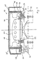
- a vehicle steering wheel gas bag module 10 is shown, which a stylized steering wheel hub 12 is attached.
- the gas bag module 10 has a pot-shaped module housing, consisting of an openable Front wall 14 and a rear protruding from the front wall 14 Circumferential wall 16.
- the module housing takes one gas bag 18 and one Gas generator 20 on.
- a base plate 22 made of die-cast aluminum or magnesium serves as a generator support, since the gas generator 20 on the base plate 22 is screwed tight.
- the bottom plate 22 is with the peripheral wall 16 by several on the circumference evenly distributed snap-in connections connected and closes the module housing back.
- the snap connections consist of snap hooks 24 on lower edge of the peripheral wall 16 through openings 26 in the bottom plate protrude and engage behind the edge of the openings 26 locking.
- the bottom plate 22 has in addition to its section lying radially inward of the peripheral wall 16 still radially outward of the openings 26 parallel to one another upward Circumferential wall 16 extending portion 28 which surrounds the circumferential wall 16 and is integrally connected to a front edge 36 which is a side Continuation of the front wall 14 forms.
- the anti-lock device is by a portion of the edge 30 of the Openings 26 formed, which provided with a bead 32 projecting downward is.
- the bead stands when the module housing is placed on the base plate 22 32, as shown on the left half of Figure 1 with broken lines, axially downwards.
- the openings 26 are thus large enough to pass through Allow snap hooks 24.
- bead-like edge 30 plastically deformed radially outwards, e.g. by Calking so that the cross section of each opening 26 is sufficiently reduced is to exclude an unlatching of the snap hook 24.
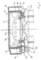
- FIG. 2 essentially corresponds to that in FIG. 1 shown, so that already introduced reference numerals for functionally identical parts to be kept.
- the release lock is in the embodiment of Figure 2 not by reshaping the edge of the Openings 26 formed.
- one is near the bottom plate 22 provided part in the form of a horn plate 50 in the area below each Opening 26 is provided with an extension 52 projecting into opening 26, which extends the Cross-section of the associated opening 26 is reduced so that it as an unlocking device serves and excludes unlatching of the associated snap hook 24.
- the horn plate 50 is otherwise module-proof, i.e. together with the module movable.
- a horn contact provided on the underside of the horn plate 50 54 comes down with one when pressing the module in the axial direction second horn contact 56 contacts a circuit for horn actuation close.
Landscapes
- Engineering & Computer Science (AREA)
- Mechanical Engineering (AREA)
- Air Bags (AREA)
- Steering Controls (AREA)
Abstract
Description
- Figur 1 eine Querschnittsansicht einer Ausführungsform de s erfindungsgemäßen Gassackmoduls und
- Figur 2 eine Querschnittsansicht einer zweiten Ausführungs form des erfindungsgemäßen Gassackmoduls.
Claims (7)
- Gassackmodul, mitgekennzeichnet durcheinem topfförmigen Modulgehäuse, das eine öffnenbare Vorderwand (14) und eine rückseitig abstehende Umfangswand (16) aufweist, sowiemit einer Bodenplatte (22), die an der Umfangswand (16) durch wenigstens einen in eine Öffnung (26) einrastbaren Schnapphaken (24) befestigt ist,eine Entrastsicherung, die den Querschnitt der Öffnung (26) nach dem Einrasten so verringert, daß ein Entrasten verhindert wird.
- Gassackmodul nach Anspruch 1, dadurch gekennzeichnet, daß die Entrastsicherung durch einen plastisch in Richtung Schnapphaken (24) verformten Abschnitt des Randes (30) der Öffnung (26) gebildet ist.
- Gassackmodul nach Anspruch 2, dadurch gekennzeichnet, daß der Rand (30) zur Bildung der Entrastsicherung einen plastisch verformten Wulst (32) aufweist.
- Gassackmodul nach Anspruch 1, dadurch gekennzeichnet, daß am Gassackmodul nahe der Bodenplatte (22) ein Bauteil mit einem als Entrastsicherung fungierenden Fortsatz (52) vorgesehen ist, der in die Öffnung (26) ragt und deren Querschnitt reduziert.
- Gassackmodul nach Anspruch 4, dadurch gekennzeichnet, daß es ein Lenkradmodul ist und das Bauteil ein mit einem Hupenkontakt (54) versehene, modulfeste Hupenplatte (50) ist.
- Gassackmodul nach einem der vorhergehenden Ansprüche, gekennzeichnet durch einen Gasgenerator (20), der an der als Generatorträger fungierenden Bodenplatte (22) befestigt ist.
- Gassackmodul nach einem der vorhergehenden Ansprüche, dadurch gekennzeichnet, daß die Bodenplatte (22) ein Aluminium- oder Magnesium-Druckgußteil ist.
Applications Claiming Priority (2)
| Application Number | Priority Date | Filing Date | Title |
|---|---|---|---|
| DE20106693U DE20106693U1 (de) | 2001-04-18 | 2001-04-18 | Gassackmodul |
| DE20106693U | 2001-04-18 |
Publications (3)
| Publication Number | Publication Date |
|---|---|
| EP1251045A2 true EP1251045A2 (de) | 2002-10-23 |
| EP1251045A3 EP1251045A3 (de) | 2003-12-03 |
| EP1251045B1 EP1251045B1 (de) | 2006-03-29 |
Family
ID=7955886
Family Applications (1)
| Application Number | Title | Priority Date | Filing Date |
|---|---|---|---|
| EP02007386A Expired - Lifetime EP1251045B1 (de) | 2001-04-18 | 2002-04-09 | Gassackmodul |
Country Status (4)
| Country | Link |
|---|---|
| US (1) | US6921103B2 (de) |
| EP (1) | EP1251045B1 (de) |
| DE (2) | DE20106693U1 (de) |
| ES (1) | ES2261544T3 (de) |
Cited By (1)
| Publication number | Priority date | Publication date | Assignee | Title |
|---|---|---|---|---|
| WO2019154894A1 (en) * | 2018-02-07 | 2019-08-15 | Autoliv Development Ab | Airbag module, method for manufacturing an airbag module and steering wheel |
Families Citing this family (8)
| Publication number | Priority date | Publication date | Assignee | Title |
|---|---|---|---|---|
| DE102004051434A1 (de) | 2004-02-18 | 2005-09-15 | Takata-Petri Ag | Gehäuse für ein Gassackmodul |
| CN100441446C (zh) * | 2004-02-18 | 2008-12-10 | 高田-彼得里公开股份有限公司 | 用于气囊组件的外壳 |
| WO2005080143A1 (de) * | 2004-02-18 | 2005-09-01 | Takata-Petri Ag | Gehäuse für ein gassackmodul |
| DE102004015529B4 (de) * | 2004-03-30 | 2009-08-27 | Key Safety Systems, Inc., Sterling Heights | Lenkrad für ein Fahrzeug |
| US7293794B2 (en) * | 2005-03-31 | 2007-11-13 | Tk Holdings Inc. | Cover attachment |
| US8491003B2 (en) | 2010-02-23 | 2013-07-23 | Judco Manufacturing, Inc. | Airbag frame apparatus |
| US8939466B2 (en) | 2010-02-23 | 2015-01-27 | Judco Partnership, Llc | Airbag frame apparatus |
| DE102017119335A1 (de) * | 2017-08-24 | 2019-02-28 | Trw Automotive Safety Systems Gmbh | Gassackmodul für ein fahrzeuglenkrad |
Family Cites Families (24)
| Publication number | Priority date | Publication date | Assignee | Title |
|---|---|---|---|---|
| US5388858A (en) * | 1991-02-25 | 1995-02-14 | Trw, Inc. | Air bag module structure and method of assembly |
| JPH04115968U (ja) * | 1991-03-28 | 1992-10-15 | 日本精工株式会社 | エアバツグカバーとハウジングとの連結構造 |
| DE4134673C1 (de) | 1991-10-19 | 1993-04-01 | Dr.Ing.H.C. F. Porsche Ag, 7000 Stuttgart, De | |
| DE69219996T2 (de) * | 1991-10-28 | 1998-01-08 | Toyoda Gosei Kk | Lenkrad mit einbegriffener Luftsackeinheit |
| US5280946A (en) * | 1992-06-01 | 1994-01-25 | Morton International, Inc. | Cover for air bag installation |
| US5354093A (en) * | 1993-04-05 | 1994-10-11 | General Motors Corporation | Air bag module having integral cover attachment |
| US5378013A (en) * | 1993-08-06 | 1995-01-03 | Ford Motor Company | Cover retainer assembly for inflatable restraint air bag |
| GB2290268B (en) * | 1994-06-07 | 1998-02-18 | Autoliv Dev | Improvements in or relating to a safety arrangement |
| GB2290267B (en) * | 1994-06-07 | 1998-02-04 | Autoliv Dev | Improvements in or relating to a safety arrangement |
| US5508482A (en) * | 1994-10-11 | 1996-04-16 | General Motors Corporation | Horn activation and steering wheel assembly |
| JP3431349B2 (ja) * | 1995-03-15 | 2003-07-28 | 株式会社東海理化電機製作所 | エアバッグカバーの保持構造 |
| DE19516255C2 (de) * | 1995-04-26 | 2000-09-21 | Petri Ag | Airbagmodul |
| DE19614276C1 (de) * | 1996-04-11 | 1997-08-28 | Autoliv Dev | Airbag-Anordnung |
| US5873596A (en) * | 1996-05-10 | 1999-02-23 | Toyoda Gosei Co., Ltd. | Air bag device having horn switch |
| US5762364A (en) * | 1996-08-01 | 1998-06-09 | Trw Inc. | Vehicle steering wheel including inflation fluid tank structure |
| JP3276581B2 (ja) * | 1996-09-27 | 2002-04-22 | 日本プラスト株式会社 | ステアリングホイール |
| US5738369A (en) * | 1996-10-09 | 1998-04-14 | Breed Automotive Technology, Inc. | Snap-on air bag and horn switch module |
| US6079737A (en) * | 1997-01-16 | 2000-06-27 | Toyoda Gosei Co., Ltd. | Steering wheel and horn switch assembly for the steering wheel |
| US6050597A (en) * | 1997-03-04 | 2000-04-18 | Trw Inc. | Horn switch for air bag module |
| GB2339408B (en) | 1998-07-10 | 2002-03-27 | Autoliv Dev | Improvements in or relating to an airbag |
| DE19837899A1 (de) | 1998-08-20 | 2000-02-24 | Takata Europ Gmbh | Gassackmodul |
| US6719323B2 (en) * | 1999-08-06 | 2004-04-13 | Honda Giken Kogyo Kabushiki Kaisha | Air bag apparatus and steering wheel |
| JP2001146142A (ja) * | 1999-11-19 | 2001-05-29 | Tokai Rika Co Ltd | エアバッグ装置 |
| JP4538956B2 (ja) * | 2000-03-17 | 2010-09-08 | タカタ株式会社 | エアバッグ装置 |
-
2001
- 2001-04-18 DE DE20106693U patent/DE20106693U1/de not_active Expired - Lifetime
-
2002
- 2002-04-09 DE DE50206184T patent/DE50206184D1/de not_active Expired - Lifetime
- 2002-04-09 ES ES02007386T patent/ES2261544T3/es not_active Expired - Lifetime
- 2002-04-09 EP EP02007386A patent/EP1251045B1/de not_active Expired - Lifetime
- 2002-04-12 US US10/122,440 patent/US6921103B2/en not_active Expired - Fee Related
Non-Patent Citations (1)
| Title |
|---|
| None |
Cited By (1)
| Publication number | Priority date | Publication date | Assignee | Title |
|---|---|---|---|---|
| WO2019154894A1 (en) * | 2018-02-07 | 2019-08-15 | Autoliv Development Ab | Airbag module, method for manufacturing an airbag module and steering wheel |
Also Published As
| Publication number | Publication date |
|---|---|
| ES2261544T3 (es) | 2006-11-16 |
| US20020153708A1 (en) | 2002-10-24 |
| EP1251045B1 (de) | 2006-03-29 |
| US6921103B2 (en) | 2005-07-26 |
| EP1251045A3 (de) | 2003-12-03 |
| DE20106693U1 (de) | 2001-08-23 |
| DE50206184D1 (de) | 2006-05-18 |
Similar Documents
| Publication | Publication Date | Title |
|---|---|---|
| DE2936468C2 (de) | Vorrichtung zur Befestigung eines Instruments in einer Vertiefung der Armaturentafel eines Kraftfahrzeugs | |
| EP0668195B1 (de) | Abdeckung für ein Gassack-Rückhaltesystem in Fahrzeugen | |
| US7320157B2 (en) | Resilient clip fastener | |
| DE19720867C1 (de) | Verfahren zum Verbinden eines mit einer Montage- oder Verbindungsöffnung versehenen Bauteils mit einem Trägerelement eines Kraftfahrzeugs, sowie eine nach dem Verfahren hergestellte Verbindung | |
| DE19522313C2 (de) | Airbagsicherheitsvorrichtung | |
| DE202018106381U1 (de) | Behälter mit Deckel | |
| EP2057043A1 (de) | Vorrichtung zur befestigung einer airbageinheit in einer baugruppe eines kraftfahrzeugs, insbesondere in einem lenkrad, durch verrasten | |
| EP2121390A2 (de) | Folienplakette für eine airbagabdeckung | |
| EP1251043A1 (de) | Baueinheit aus Gassackmodul und Fahrzeuglenkrad | |
| US5971686A (en) | Retained fastener | |
| DE10297288T5 (de) | Lasche zur Einstellung der Z-Höhe eines Airbagmoduls | |
| DE19521937A1 (de) | Sicherheitsvorrichtung | |
| EP1251042B1 (de) | Gassack-Modul | |
| EP1251045B1 (de) | Gassackmodul | |
| US4356592A (en) | Vehicle assist strap | |
| DE102009059996A1 (de) | Fußstütze für ein Fahrzeug | |
| DE19911930B4 (de) | Airbagmodul | |
| EP1426248B1 (de) | Gassackmodul | |
| EP0974757B1 (de) | Befestigungsvorrichtung für flächige Bauteile | |
| EP1452404B1 (de) | Gassackmodul für Lenkrad | |
| EP1544029A2 (de) | An einem Fahrzeugboden anbringbare Fussstütze | |
| DE19850463A1 (de) | Luftsackmodul und Verfahren zu dessen Herstellung | |
| DE60111890T2 (de) | Verriegelungselemente zum Halten eines Zubehörteiles an der Tragstruktur eines Kraftfahrzeuges | |
| DE3308817A1 (de) | Integrale befestigung zugbelasteter bauteile mit direkter kraftuebertragung | |
| EP1108625B1 (de) | Gassack-Modul mit Rastverbindung und nabentopfförmigem Aufnahmekörper |
Legal Events
| Date | Code | Title | Description |
|---|---|---|---|
| PUAI | Public reference made under article 153(3) epc to a published international application that has entered the european phase |
Free format text: ORIGINAL CODE: 0009012 |
|
| AK | Designated contracting states |
Kind code of ref document: A2 Designated state(s): AT BE CH CY DE DK ES FI FR GB GR IE IT LI LU MC NL PT SE TR |
|
| AX | Request for extension of the european patent |
Free format text: AL;LT;LV;MK;RO;SI |
|
| PUAL | Search report despatched |
Free format text: ORIGINAL CODE: 0009013 |
|
| AK | Designated contracting states |
Kind code of ref document: A3 Designated state(s): AT BE CH CY DE DK ES FI FR GB GR IE IT LI LU MC NL PT SE TR |
|
| AX | Request for extension of the european patent |
Extension state: AL LT LV MK RO SI |
|
| 17P | Request for examination filed |
Effective date: 20040513 |
|
| AKX | Designation fees paid |
Designated state(s): DE ES FR GB IT |
|
| 17Q | First examination report despatched |
Effective date: 20050103 |
|
| RBV | Designated contracting states (corrected) |
Designated state(s): DE ES FR GB IT |
|
| GRAP | Despatch of communication of intention to grant a patent |
Free format text: ORIGINAL CODE: EPIDOSNIGR1 |
|
| GRAS | Grant fee paid |
Free format text: ORIGINAL CODE: EPIDOSNIGR3 |
|
| GRAA | (expected) grant |
Free format text: ORIGINAL CODE: 0009210 |
|
| RAP1 | Party data changed (applicant data changed or rights of an application transferred) |
Owner name: TRW AUTOMOTIVE SAFETY SYSTEMS GMBH |
|
| AK | Designated contracting states |
Kind code of ref document: B1 Designated state(s): DE ES FR GB IT |
|
| PG25 | Lapsed in a contracting state [announced via postgrant information from national office to epo] |
Ref country code: GB Free format text: LAPSE BECAUSE OF FAILURE TO SUBMIT A TRANSLATION OF THE DESCRIPTION OR TO PAY THE FEE WITHIN THE PRESCRIBED TIME-LIMIT Effective date: 20060329 |
|
| REG | Reference to a national code |
Ref country code: GB Ref legal event code: FG4D Free format text: NOT ENGLISH |
|
| PGFP | Annual fee paid to national office [announced via postgrant information from national office to epo] |
Ref country code: FR Payment date: 20060403 Year of fee payment: 5 |
|
| PGFP | Annual fee paid to national office [announced via postgrant information from national office to epo] |
Ref country code: ES Payment date: 20060424 Year of fee payment: 5 |
|
| REF | Corresponds to: |
Ref document number: 50206184 Country of ref document: DE Date of ref document: 20060518 Kind code of ref document: P |
|
| ET | Fr: translation filed | ||
| GBV | Gb: ep patent (uk) treated as always having been void in accordance with gb section 77(7)/1977 [no translation filed] |
Effective date: 20060329 |
|
| REG | Reference to a national code |
Ref country code: ES Ref legal event code: FG2A Ref document number: 2261544 Country of ref document: ES Kind code of ref document: T3 |
|
| PLBE | No opposition filed within time limit |
Free format text: ORIGINAL CODE: 0009261 |
|
| STAA | Information on the status of an ep patent application or granted ep patent |
Free format text: STATUS: NO OPPOSITION FILED WITHIN TIME LIMIT |
|
| 26N | No opposition filed |
Effective date: 20070102 |
|
| PGFP | Annual fee paid to national office [announced via postgrant information from national office to epo] |
Ref country code: IT Payment date: 20070529 Year of fee payment: 6 |
|
| REG | Reference to a national code |
Ref country code: ES Ref legal event code: FD2A Effective date: 20070410 |
|
| PG25 | Lapsed in a contracting state [announced via postgrant information from national office to epo] |
Ref country code: FR Free format text: LAPSE BECAUSE OF NON-PAYMENT OF DUE FEES Effective date: 20070430 |
|
| PG25 | Lapsed in a contracting state [announced via postgrant information from national office to epo] |
Ref country code: ES Free format text: LAPSE BECAUSE OF NON-PAYMENT OF DUE FEES Effective date: 20070410 |
|
| PG25 | Lapsed in a contracting state [announced via postgrant information from national office to epo] |
Ref country code: IT Free format text: LAPSE BECAUSE OF NON-PAYMENT OF DUE FEES Effective date: 20080409 |
|
| PGFP | Annual fee paid to national office [announced via postgrant information from national office to epo] |
Ref country code: DE Payment date: 20190430 Year of fee payment: 18 |
|
| REG | Reference to a national code |
Ref country code: DE Ref legal event code: R119 Ref document number: 50206184 Country of ref document: DE |
|
| PG25 | Lapsed in a contracting state [announced via postgrant information from national office to epo] |
Ref country code: DE Free format text: LAPSE BECAUSE OF NON-PAYMENT OF DUE FEES Effective date: 20201103 |