EP1250212B1 - Apparatus for adhering a clamp to a hose - Google Patents
Apparatus for adhering a clamp to a hose Download PDFInfo
- Publication number
- EP1250212B1 EP1250212B1 EP01903333A EP01903333A EP1250212B1 EP 1250212 B1 EP1250212 B1 EP 1250212B1 EP 01903333 A EP01903333 A EP 01903333A EP 01903333 A EP01903333 A EP 01903333A EP 1250212 B1 EP1250212 B1 EP 1250212B1
- Authority
- EP
- European Patent Office
- Prior art keywords
- clamp
- hose assembly
- hose
- tooling
- adhesive
- Prior art date
- Legal status (The legal status is an assumption and is not a legal conclusion. Google has not performed a legal analysis and makes no representation as to the accuracy of the status listed.)
- Expired - Lifetime
Links
Images











Classifications
-
- B—PERFORMING OPERATIONS; TRANSPORTING
- B25—HAND TOOLS; PORTABLE POWER-DRIVEN TOOLS; MANIPULATORS
- B25B—TOOLS OR BENCH DEVICES NOT OTHERWISE PROVIDED FOR, FOR FASTENING, CONNECTING, DISENGAGING, OR HOLDING
- B25B25/00—Implements for fastening, connecting or tensioning of wire or strip
- B25B25/005—Implements for fastening, connecting or tensioning of wire or strip for applying wire clasps to hose couplings
-
- B—PERFORMING OPERATIONS; TRANSPORTING
- B23—MACHINE TOOLS; METAL-WORKING NOT OTHERWISE PROVIDED FOR
- B23P—METAL-WORKING NOT OTHERWISE PROVIDED FOR; COMBINED OPERATIONS; UNIVERSAL MACHINE TOOLS
- B23P19/00—Machines for simply fitting together or separating metal parts or objects, or metal and non-metal parts, whether or not involving some deformation; Tools or devices therefor so far as not provided for in other classes
- B23P19/04—Machines for simply fitting together or separating metal parts or objects, or metal and non-metal parts, whether or not involving some deformation; Tools or devices therefor so far as not provided for in other classes for assembling or disassembling parts
- B23P19/08—Machines for placing washers, circlips, or the like on bolts or other members
- B23P19/084—Machines for placing washers, circlips, or the like on bolts or other members for placing resilient or flexible rings, e.g. O-rings, circlips
-
- F—MECHANICAL ENGINEERING; LIGHTING; HEATING; WEAPONS; BLASTING
- F16—ENGINEERING ELEMENTS AND UNITS; GENERAL MEASURES FOR PRODUCING AND MAINTAINING EFFECTIVE FUNCTIONING OF MACHINES OR INSTALLATIONS; THERMAL INSULATION IN GENERAL
- F16L—PIPES; JOINTS OR FITTINGS FOR PIPES; SUPPORTS FOR PIPES, CABLES OR PROTECTIVE TUBING; MEANS FOR THERMAL INSULATION IN GENERAL
- F16L33/00—Arrangements for connecting hoses to rigid members; Rigid hose-connectors, i.e. single members engaging both hoses
- F16L33/02—Hose-clips
-
- Y—GENERAL TAGGING OF NEW TECHNOLOGICAL DEVELOPMENTS; GENERAL TAGGING OF CROSS-SECTIONAL TECHNOLOGIES SPANNING OVER SEVERAL SECTIONS OF THE IPC; TECHNICAL SUBJECTS COVERED BY FORMER USPC CROSS-REFERENCE ART COLLECTIONS [XRACs] AND DIGESTS
- Y10—TECHNICAL SUBJECTS COVERED BY FORMER USPC
- Y10T—TECHNICAL SUBJECTS COVERED BY FORMER US CLASSIFICATION
- Y10T29/00—Metal working
- Y10T29/49—Method of mechanical manufacture
- Y10T29/49826—Assembling or joining
- Y10T29/49885—Assembling or joining with coating before or during assembling
-
- Y—GENERAL TAGGING OF NEW TECHNOLOGICAL DEVELOPMENTS; GENERAL TAGGING OF CROSS-SECTIONAL TECHNOLOGIES SPANNING OVER SEVERAL SECTIONS OF THE IPC; TECHNICAL SUBJECTS COVERED BY FORMER USPC CROSS-REFERENCE ART COLLECTIONS [XRACs] AND DIGESTS
- Y10—TECHNICAL SUBJECTS COVERED BY FORMER USPC
- Y10T—TECHNICAL SUBJECTS COVERED BY FORMER US CLASSIFICATION
- Y10T29/00—Metal working
- Y10T29/49—Method of mechanical manufacture
- Y10T29/49826—Assembling or joining
- Y10T29/49908—Joining by deforming
- Y10T29/49925—Inward deformation of aperture or hollow body wall
-
- Y—GENERAL TAGGING OF NEW TECHNOLOGICAL DEVELOPMENTS; GENERAL TAGGING OF CROSS-SECTIONAL TECHNOLOGIES SPANNING OVER SEVERAL SECTIONS OF THE IPC; TECHNICAL SUBJECTS COVERED BY FORMER USPC CROSS-REFERENCE ART COLLECTIONS [XRACs] AND DIGESTS
- Y10—TECHNICAL SUBJECTS COVERED BY FORMER USPC
- Y10T—TECHNICAL SUBJECTS COVERED BY FORMER US CLASSIFICATION
- Y10T29/00—Metal working
- Y10T29/51—Plural diverse manufacturing apparatus including means for metal shaping or assembling
- Y10T29/5136—Separate tool stations for selective or successive operation on work
- Y10T29/5137—Separate tool stations for selective or successive operation on work including assembling or disassembling station
-
- Y—GENERAL TAGGING OF NEW TECHNOLOGICAL DEVELOPMENTS; GENERAL TAGGING OF CROSS-SECTIONAL TECHNOLOGIES SPANNING OVER SEVERAL SECTIONS OF THE IPC; TECHNICAL SUBJECTS COVERED BY FORMER USPC CROSS-REFERENCE ART COLLECTIONS [XRACs] AND DIGESTS
- Y10—TECHNICAL SUBJECTS COVERED BY FORMER USPC
- Y10T—TECHNICAL SUBJECTS COVERED BY FORMER US CLASSIFICATION
- Y10T29/00—Metal working
- Y10T29/51—Plural diverse manufacturing apparatus including means for metal shaping or assembling
- Y10T29/5147—Plural diverse manufacturing apparatus including means for metal shaping or assembling including composite tool
-
- Y—GENERAL TAGGING OF NEW TECHNOLOGICAL DEVELOPMENTS; GENERAL TAGGING OF CROSS-SECTIONAL TECHNOLOGIES SPANNING OVER SEVERAL SECTIONS OF THE IPC; TECHNICAL SUBJECTS COVERED BY FORMER USPC CROSS-REFERENCE ART COLLECTIONS [XRACs] AND DIGESTS
- Y10—TECHNICAL SUBJECTS COVERED BY FORMER USPC
- Y10T—TECHNICAL SUBJECTS COVERED BY FORMER US CLASSIFICATION
- Y10T29/00—Metal working
- Y10T29/53—Means to assemble or disassemble
- Y10T29/53313—Means to interrelatedly feed plural work parts from plural sources without manual intervention
-
- Y—GENERAL TAGGING OF NEW TECHNOLOGICAL DEVELOPMENTS; GENERAL TAGGING OF CROSS-SECTIONAL TECHNOLOGIES SPANNING OVER SEVERAL SECTIONS OF THE IPC; TECHNICAL SUBJECTS COVERED BY FORMER USPC CROSS-REFERENCE ART COLLECTIONS [XRACs] AND DIGESTS
- Y10—TECHNICAL SUBJECTS COVERED BY FORMER USPC
- Y10T—TECHNICAL SUBJECTS COVERED BY FORMER US CLASSIFICATION
- Y10T29/00—Metal working
- Y10T29/53—Means to assemble or disassemble
- Y10T29/53657—Means to assemble or disassemble to apply or remove a resilient article [e.g., tube, sleeve, etc.]
Definitions
- This invention relates to apparatus and method to be utilized by an operator in an automated process of adhering a clamp, normally a circular metal clamp, to a tubular hose.
- a clamp normally a circular metal clamp
- scrub/roughen e. g. prepare
- a spot on the end region of the hose to which a clamp will be secured place a metered amount of quick-setting adhesive on that region, move a clamp into precise position spaced from the adhesive and then press the clamp into position while the adhesive sets.
- the apparatus for accomplishing these steps must be precise, simple to use (e. g. to load and unload the clamps and hose), and have capability to accommodate a substantial variety of hose pieces and clamps with simple change of type specific tooling.
- United States Patent No. 5,145,218 discloses a hose construction and a method according to the preamble of claim 8.
- a toggle clamping means is directly glued to the hose by a single spot of adhesive disposed between the clamping means and the hose.
- Japanese patent number 58211836 discloses an apparatus according to the preamble of claim 1.
- An apparatus for precisely locating a uniquely shaped hose assembly for attachment of a clamp thereto at a predetermined attachment location on the hose assembly comprises clamp tooling adapted to orient a hose clamp including means for receiving a hose clamp and presenting the clamp in a predetermined attachment position, a mounting device for receiving said clamp tooling, cooperating hose positioning tooling adapted to support a unique hose assembly properly aligned with a clamp presented at the predetermined attachment position, said hose positioning tooling being designed to locate the hose assembly with its attachment location aligned with a clamp in said clamp tooling, and means for pressing together the clamp and the hose assembly at the attachment location while the adhesive sets, characterized in that the apparatus further includes means for scrubbing the attachment location on the hose assembly, means for depositing a measured quantity of adhesive to the attachment location, and means associated with said clamp tooling for moving a clamp therein into engagement with the deposited adhesive at the attachment location on the supported hose assembly.
- a length of shaped tubing is fitted with metal clamp(s) 12 at predetermined spacings from one or more of its opposite ends 14.
- the invention is applicable to hose or tubing of various sizes, shapes and materials (hereinafter identified as a hose assembly), may include branches so an assembly has more than two ends, and the clamps may be metallic or other equivalent material, and may be fitted to one or more ends of the hose assembly.
- the clamps 10 illustrated are of a well known pre-tensioned type which are latched in an open position prior to attachment to the hose.
- clamps are usually released in later assembly operations when the ends of the tubing and clamp assembly are placed on ferrules or other connectors, so as to clamp the hose in that end position.
- other types of clamps can be fitted to hose assemblies with the apparatus of this invention.
- the tubing or hose can have various inner and outer diameters, and various bends or curves which are unique to the intended installation of the completed hose assembly with attached clam. It is important that the clamps be properly spaced at a predetermined distance from the end of the hose to which it is attached, and that the clamp be in proper circular orientation with respect to the shape of the hoses or tubes making up the assembly. This assures that the clamp will be positioned over a ferrule or connector, and at a predetermined angular orientation, when it is installed in its intended environment to allow convenient release or operation of the clamp mechanism.
- each hose and clamp assembly has a unique set of parameters for the alignment of clamp and hose before the clamp is adhered to the hose end
- a table 20 has a top 22 and a lower shelf 24.
- the table is preferably of a somewhat wedge shape in plan view, with the forward end 25 of top 22 located at an operator's station S.
- a tool holder 30 which is adapted to receive various tooling which locates and supports a ring-like clamp to be attached, and also defines the receptor and indexer for a hose end. Typical such tooling is shown in Figs. 4-6.
- a hose locating tool 26 (Fig. 2) which is a part of the interchangeable tooling, and comprising an index base 27 secured to top 22, an upward extending stand 28, and a hose receptor 29.
- Parts 28 and 29 are of unique shape and dimension according to the size, shape, and predetermined positioning of the hose in the apparatus.
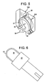
- Fig. 5 shows the opposing sections 32A and 32B of a clamp receiver and carrier 34 which is supported on a movable plate 35 (Figs. 4A & B), and defines through the middle of carrier 34 a central cylindrical opening 36 having a counterbored opening 37 for receiving the periphery of a clamp such as shown in Fig. 1, and having upper and lower gaps 38 to embrace the clamp.
- Plate 35 is part of the tooling support and actuation shown in Figs. 4A & 4B as viewed from the back and side of table 20.
- Fig. 6 illustrates the mandrel 40 and its surrounding stop ring 42 which mounts upon, and extends forward from, the rear vertical post 45 projecting upward from the base plate 46 of the tooling support structure, which base plate is secured to table top 22.
- the nose 43 of mandrel 40 receives the open end of a hose and stop ring 42 defines an index point for positioning the hose end along its length, that is, along the Z axis of the hose end, by pushing the hose end against the stop ring.
- a horizontal positioning mechanism is supported on post 45, and includes a pair of guided slide rods 48 and a pneumatic cylinder 52.
- the rod 50 of cylinder 52 and the slide rods all extend forward to, and terminate in, the rear of a horizontally movable block 56. Together these parts are the major parts of a reciprocating mechanism 54 carrying the main support plate 57 which extends upward above (and free from) base plate 46.
- Block 56 is fastened to the back of a horizontally movable plate 57 of the clamping mechanism 60 which carries movable plate 35.
- a bracket 58 at the top of plate 35 provides the attachment and support for the sections 32A, 32B of the clamp receiver with openings 36, 37 surrounding mandrel 40.
- the clamping mechanism 60 comprises the front plate 35, which is attached to a vertically acting pneumatic cylinder 65 having its rod ends 66 connected between upper and lower brackets 62 projecting forward from plate 57.
- the body of cylinder 65 is attached to front plate 35. Actuation of cylinder 65 causes limited vertical motion of plate 35 and the attached sections 32A, 32B of the clamp receiver 32, between an upper position clear of the end of a hose on mandrel 40 (before a spot of adhesive is applied to the hose end), and a lower clamping position wherein the clamp is pressed against the glue spot on the hose end.
- the sections 32A, 32B have a clamping action against the hose end, and the mandrel 40 functions as an anvil supporting the inner portion of the hose end.
- Air under pressure is supplied to the pneumatic cylinder 52 through ports connections 52A, 52B to pressurize and/or vent the opposite chambers of the cylinder and produce the forward/rearward motion of the tooling. Similarly, air under pressure is supplied to the appropriate chambers of cylinder 65 to produce the up/down action of the tooling.
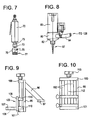
- the scrubbing tool is shown as a conventional in-line rotary pneumatic driver 70 having a collet 72 on its drive shaft 73 to hold the scrubbing tool 75.
- This tool comprises a base 76 and a frusto-conical wheel array of fibers 77.
- the fibers are formed of carbon impregnated silicone strands.
- Fig. 8 shows the adhesive dispenser, in the form of a cylindrical body 80 with a cup-like part 82 at its bottom connected to an adhesive supply tube 84 extending from a source of adhesive under pressure (later described).
- a solenoid operated valve 85 controls flow from tube 84 into part 82, which in turn is fitted with a tapered nozzle 87 (preferably replaceable) from which a controlled quantity of adhesive is dispensed onto the end of a hose supported on mandrel 40.
- the scrubbing tool and the adhesive dispenser are supported on a horizontally extending slide way 90 (Figs. 2 & 3) above and extending transversely to mandrel 40.
- a pair of separate but similar support brackets 91 and 92 are mounted upon a slide way 94 (Fig. 3), spaced apart a predetermined distance such that one or the other can be located over the center of the clamp tooling, or at a center location where each is located on opposite sides of that center.
- the support brackets 91, 92 each include a vertically extending back plate 95 and an arm 96 extending rearward and downward of plate 95 and having a horizontally extending slide 97 at its bottom, spaced rearwardly of plate 95.
- the lower portion of plate 95 and the bottom of slide 97 are mounted to slide way 90.
- Upper and lower blocks 100 and 101 extend forward from plate 95 and carry between them spaced apart vertically arranged rods 102 which form a guide for an L-shaped carrier bracket 105 which has a receiving/mounting aperture 106 in its horizontal section 107 that embraces and holds the dispenser body 80 (on one bracket) and the body 70 of the scrubber driver (in the other bracket).
- the vertical section 108 of the carrier bracket has spaced apart cross-bars 110 which have appropriate holes for receiving rods 102 and forming a vertically adjustable restraint for bracket 105.
- a threaded rod 112 with an adjustment knob 113 extends through block 100 and is seated in block 101, and has a treaded connection to internal threads in one or both of cross-bars 110.
- Rotation of knob 113 will cause raising or lowering of bracket 105 to set the operating level of the scrubbing tool 75 and the level of the adhesive dispensing nozzle 87.
- an enclosed adhesive reservoir 120 (Figs. 2,3,11 & 12).
- This reservoir acts as the supply source for liquid adhesive, and comprises a closed body 122 including a removable cover 124 held in sealed relation to the body by several screw-type clamps 125.
- a compressed air fitting 126 is fitted to cover 124 to allow pressurizing the reservoir interior, and cover 124 includes a depending intake tube (not shown) which is connected to the bottom of an adhesive outlet fitting 127 and has a ferrule at it exterior for attachment of an adhesive supply tube 128 which leads to the dispenser body 80.
- the adhesive storage include an open top pot (not shown) set within reservoir body 122, into which the intake tube descends. Normal operating pressure in reservoir 120 is in the order of 5 p. s. I (35 100 N/m 2 ).
- Fig. 13 illustrates schematically the pneumatics of the apparatus.
- the compressed air supply may be from any suitable source; in a manufacturing environment this often a"shop air"connection which supplies compressed air in sufficient volume at a pressure in the order of 90 p. s. i. (6,33.10 5 N/m 2 ).
- the inlet air is routed through a filter and pressure regulator module, and then to the adhesive (glue) reservoir 120 and through a dump valve module to a) a further regulator which has its output connected through an oiler to the buffer motor 70 and to the various pneumatic cylinders (previously described) including the clamping head.
- the apparatus is semi-automated under the control of a digital microprocessor.
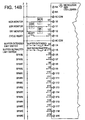
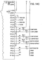
- a digital microprocessor In an actual embodiment, an Allen-Bradley Micrologix 1000 microprocessor is employed, as shown in Fig. 14.
- a power supply control circuit including manually operated Right & Left optical switches (LOS & ROS) which must be actuated simultaneously to initiate an operating cycle.
- the physical spaced apart location of these is shown in Figs. 2 and 3.
- LOS & ROS Right & Left optical switches
- the angularly mounted box 130 to the left and behind slide way 90, houses the manually operated switches marked control power ON, power OFF, and cycle reset CR.
- the hand (palm) actuated switch ER is an emergency stop switch that, when actuated by the operator, causes all air pressure in the system to be dumped, immediately disabling and stopping the apparatus.
- Fig. 14 also illustrates (right side) the pin connections for the microprocessor, and the related notations identify the mechanical functions of the apparatus which are under this control.
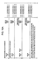
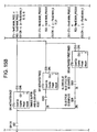
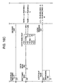
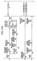
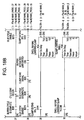
- Figs. 15-19 together illustrate sequential step-by-step control functions of the processor. The notations on these drawings provide a full description of the control system in detail which is sufficient to fully describe the same in detail sufficient to allow one skilled in this art to reproduce the system.
- the height of glue nozzle is adjusted to assure the glue "spot" will be properly placed on the end of the hose, and the scrubber functions is visibly checked for accuracy of its alignment and action on the hose end where the "spot" is to be placed.
- the processor is adjusted for the desired time the clamping action is maintained, and for the response time of the emergency stop (air pressure dump) operation. Once these adjustments are complete, the operator may begin assembly operation.
- a fully automatic mode to run the desired quantity of a job order the operator has only to supply a hose and a clamp into the tooling (alignment is assured by the placement of the tooling), initiate the operating cycle using the two optical switches, and remove the hose-clamp assembly when the cycle is finished.
- the system is also capable of operating in a semi-automatic mode, wherein the operation of glue spot deposit is controlled by a foot treadle actuated switch TS (Figs. 2 & 3) which is then connected independently of the automatic cycle controller. In that case, the apparatus functions up to the point where the control is ready to actuate the glue spot valve, and then halts. When the operator actuates the treadle switch, the solenoid valve 80 opening is initiated, and the apparatus completes the cycle.
Landscapes
- Engineering & Computer Science (AREA)
- Mechanical Engineering (AREA)
- General Engineering & Computer Science (AREA)
- Lining Or Joining Of Plastics Or The Like (AREA)
Description
Claims (10)
- Apparatus for precisely locating a uniquely shaped hose assembly (10) for attachment of a clamp (12) thereto at a predetermined attachment location on the hose assembly (10), said apparatus comprising clamp tooling (34) adapted to orient a hose clamp (12) including means (37) for receiving a hose clamp (12) and presenting the clamp (12) in a predetermined attachment position, a mounting device (35) for receiving said clamp tooling (34), cooperating hose positioning tooling (26) adapted to support a unique hose assembly (10) properly aligned with a clamp (12) presented at the predetermined attachment position, said hose positioning tooling (26) being designed to locate the hose assembly (10) with its attachment location aligned with a clamp (12) in said clamp tooling (34), and means for pressing together the clamp (12) and the hose assembly (10) at the attachment location while the adhesive sets, characterized in that the apparatus further includes
means for scrubbing (75) the attachment location on the hose assembly (10),
means for depositing (80, 82, 84, 87) a measured quantity of adhesive to the attachment location, and
means associated with said clamp tooling (34) for moving a clamp (12) therein into engagement with the deposited adhesive at the attachment location on the supported hose assembly (10). - Apparatus as defined in claim 1, further including a control system for operating the actions of said clamp tooling (34), said hose assembly positioning means (26), said adhesive depositing means (80, 82, 84, 87), and said pressing means, so as to automatically perform the joining of a hose assembly (10) and a clamp (12) once they are loaded into the apparatus.
- Apparatus as defined in claim 1 further including a control for all said means including a programmable processor to operate said means through a cycle initiated after loading of a clamp (12) and hose assembly (10) and finished when the clamp (12) is attached to the hose assembly (10) and prepared for unloading from the apparatus.
- Apparatus as defined in claim 3, wherein the cycle is interrupted at the point where adhesive is to be applied, that function then initiated by an operator, and thereafter the cycle is completed by the control
- Apparatus as defined in any preceding claim, wherein said hose assembly positioning tooling (26) includes a unique receptor (40) matched to the hose assembly (10),
a mount (42) for said receptor (40) adapted to locate the attachment location of each hose assembly (10) placed therein into predetermined alignment with a clamp (12) in said clamp tooling (34). - Apparatus as defined in any preceding claim, wherein said scrubbing means (75) is movably supported adjacent said clamp tooling (34), and comprising
an abrading tool (77) in said scrubbing means (75) for preparing an attachment location on the positioned hose assembly (10),
means for moving (70) said abrading tool (77) between a retracted position spaced from the hose assembly (10) and a scrubbing position in contact with the attachment location of the hose assembly (10). - Apparatus as defined in any preceding claim, wherein said adhesive depositing means (80, 82, 84, 87) is movably supported adjacent said clamp tooling (34),
a nozzle (87) connected to a supply of adhesive for applying a selected amount of adhesive to the attachment location on the positioned hose assembly (10),
means for moving said adhesive depositing means (80, 82, 84, 87) between a retracted position spaced from the hose assembly (10) and an application position in which said nozzle (87) is closely spaced from the attachment location of the hose assembly (10). - A method of attaching a clamp (12) to a defined attachment location on a uniquely shaped hose assembly (10) comprisinga) placing a clamp (12) and a corresponding hose assembly (10) into tooling receptors (34) which align those parts in a unified apparatus andb) pressing and holding the clamp (12), adhesive, and the attachment location of the hose assembly (10) together for a period sufficient to allow the adhesive to set, characterized in that the method further includes the step ofc) scrubbing an attachment location on the hose assembly (10),d) then placing a predetermined quantity of adhesive on that attachment location, ande) bringing the clamp (12) into position surrounding the hose assembly (10) at the attachment location.
- The method of claim 8, wherein step (a) further includes the steps of placing the clamp (12) and hose assembly (10) in cooperating tooling (34) which includes the receptor and which is opened prior to the loading, and opening the tooling (34) to allow removal of the finished part and loading of another clamp (12) and hose into the tooling (34).
- The method of claim 8 or 9, wherein all the steps are performed under the control of a programmable processor to perform the method through a cycle initiated after loading of a clamp (12) and hose assembly (10) and finished when the clamp (12) is attached to the hose assembly (10).
Applications Claiming Priority (4)
| Application Number | Priority Date | Filing Date | Title |
|---|---|---|---|
| US17859000P | 2000-01-28 | 2000-01-28 | |
| US178590P | 2000-01-28 | ||
| PCT/US2001/002535 WO2001054859A1 (en) | 2000-01-28 | 2001-01-26 | Apparatus for adhering a clamp to a hose |
| US10/182,171 US7111389B2 (en) | 2000-01-28 | 2001-01-26 | Apparatus for adhering a clamp to a hose |
Publications (2)
| Publication Number | Publication Date |
|---|---|
| EP1250212A1 EP1250212A1 (en) | 2002-10-23 |
| EP1250212B1 true EP1250212B1 (en) | 2004-03-24 |
Family
ID=22653147
Family Applications (1)
| Application Number | Title | Priority Date | Filing Date |
|---|---|---|---|
| EP01903333A Expired - Lifetime EP1250212B1 (en) | 2000-01-28 | 2001-01-26 | Apparatus for adhering a clamp to a hose |
Country Status (6)
| Country | Link |
|---|---|
| US (1) | US7111389B2 (en) |
| EP (1) | EP1250212B1 (en) |
| CA (1) | CA2396790C (en) |
| DE (1) | DE60102445T2 (en) |
| MX (1) | MXPA02007315A (en) |
| WO (1) | WO2001054859A1 (en) |
Cited By (1)
| Publication number | Priority date | Publication date | Assignee | Title |
|---|---|---|---|---|
| CN110370214A (en) * | 2019-06-21 | 2019-10-25 | 江苏卓玉智能科技有限公司 | A kind of battery O-ring installing mechanism |
Families Citing this family (10)
| Publication number | Priority date | Publication date | Assignee | Title |
|---|---|---|---|---|
| FR2831641B1 (en) * | 2001-10-30 | 2004-02-27 | C F Gomma Barre Thomas | CLAMPING DEVICE FOR PIPES, OR THE LIKE, AND ITS MANUFACTURING METHOD |
| DE10222732A1 (en) | 2002-05-23 | 2003-12-18 | Rasmussen Gmbh | Clamp for clamping a hose on a pipe by means of a spring band, the end sections of which can be locked in the expanded state, and unlocking device for the clamp |
| US20040134586A1 (en) * | 2003-01-08 | 2004-07-15 | Cook Lawrence J. | Pneumatically actuated assembly apparatus and method of assembly |
| US20080319007A1 (en) * | 2007-06-21 | 2008-12-25 | Protia, Llc | Deuterium-enriched montelukast |
| CN104002136B (en) * | 2014-06-11 | 2016-08-24 | 佛山市谱乐飞电器实业有限公司 | A kind of multifunction machine |
| RU2728701C9 (en) | 2015-07-22 | 2020-10-15 | Конинклейке Филипс Н.В. | Bronchoscope guide for non-invasive artificial ventilation and method |
| US10584815B2 (en) | 2016-03-31 | 2020-03-10 | Cooper-Standard Automotive Inc. | Clamping arrangement with elastomeric retaining member |
| CN109262536A (en) * | 2018-11-16 | 2019-01-25 | 宁波智能制造技术研究院有限公司 | A kind of horizontal circumference special-shaped shell body protective materials semi-automatic assembling device |
| CN113134802A (en) * | 2020-01-17 | 2021-07-20 | 鸿富锦精密电子(成都)有限公司 | Twisting jig and glue dispensing mechanism adopting same |
| CN111300039B (en) * | 2020-04-03 | 2024-09-20 | 四川省胜顺鸿兴模具有限公司 | A clamp, hose, joint installation machine and installation process |
Family Cites Families (10)
| Publication number | Priority date | Publication date | Assignee | Title |
|---|---|---|---|---|
| US3360846A (en) * | 1965-03-15 | 1968-01-02 | Herman J. Schellstede | Method of securing a collar on a pipe |
| US3406905A (en) * | 1966-09-21 | 1968-10-22 | United Shoe Machinery Corp | Apparatus for atomizing and spraying thermoplastic materials |
| DE2339838C2 (en) * | 1973-08-07 | 1983-11-17 | Fichtel & Sachs Ag, 8720 Schweinfurt | Attachment of an elastic tubular body on a cylindrical component |
| US4122733A (en) * | 1977-08-01 | 1978-10-31 | Punch-Lok Company | Hose clamp applying and removing machine |
| JPS58211836A (en) | 1982-06-01 | 1983-12-09 | Toyoda Autom Loom Works Ltd | Automatic mounting device of clamp metallic fitting |
| US4899428A (en) * | 1989-08-01 | 1990-02-13 | Hsu Kuo H | Golf club handle sleeve assembling mechanism |
| US5145218A (en) * | 1990-05-30 | 1992-09-08 | Dayco Products, Inc. | Hose construction and method of making the same with adhesively bonded clamp |
| JPH08132324A (en) | 1994-11-08 | 1996-05-28 | Nissan Motor Co Ltd | Hose clamp automatic assembly device |
| JP3567036B2 (en) | 1995-12-19 | 2004-09-15 | 山口工業株式会社 | Clip assembling machine |
| US5675871A (en) * | 1996-10-10 | 1997-10-14 | Acd Tridon Inc. | Hose clamp location device |
-
2001
- 2001-01-26 MX MXPA02007315A patent/MXPA02007315A/en active IP Right Grant
- 2001-01-26 CA CA002396790A patent/CA2396790C/en not_active Expired - Lifetime
- 2001-01-26 EP EP01903333A patent/EP1250212B1/en not_active Expired - Lifetime
- 2001-01-26 US US10/182,171 patent/US7111389B2/en not_active Expired - Lifetime
- 2001-01-26 DE DE60102445T patent/DE60102445T2/en not_active Expired - Lifetime
- 2001-01-26 WO PCT/US2001/002535 patent/WO2001054859A1/en not_active Ceased
Cited By (1)
| Publication number | Priority date | Publication date | Assignee | Title |
|---|---|---|---|---|
| CN110370214A (en) * | 2019-06-21 | 2019-10-25 | 江苏卓玉智能科技有限公司 | A kind of battery O-ring installing mechanism |
Also Published As
| Publication number | Publication date |
|---|---|
| WO2001054859A1 (en) | 2001-08-02 |
| DE60102445D1 (en) | 2004-04-29 |
| EP1250212A1 (en) | 2002-10-23 |
| US20040025318A1 (en) | 2004-02-12 |
| US7111389B2 (en) | 2006-09-26 |
| MXPA02007315A (en) | 2003-10-06 |
| CA2396790C (en) | 2008-06-17 |
| DE60102445T2 (en) | 2005-01-20 |
| CA2396790A1 (en) | 2001-08-02 |
Similar Documents
| Publication | Publication Date | Title |
|---|---|---|
| CA2396790C (en) | Apparatus for adhering a clamp to a hose | |
| CN100411795C (en) | Automatic electrode replacing device for fine hole electric discharge machine | |
| CN104051927A (en) | Electric wire terminal processing device | |
| CN112791913A (en) | Mobile phone camera cable dispensing equipment | |
| CN108777226A (en) | High-frequency inductor coil installs equipment | |
| CN118739754B (en) | Magnetic steel gluing assembly station for new energy motor and production process of magnetic steel gluing assembly station | |
| CN215612783U (en) | Mobile phone camera winding displacement dispensing equipment | |
| US5027636A (en) | Feeder mechanism for applicator die | |
| CN110625218A (en) | An automatic wire welding machine for earphone plugs and its working method | |
| US5648025A (en) | Method for making light cured ophthalmic lens blocks | |
| CN214291862U (en) | An electric wheel hub fixing nut assembly machine | |
| CN119703758A (en) | Automatic assembly machine for fuel pump accessories | |
| CN115194438A (en) | Rubber-insulated-wire lamp encapsulation equipment | |
| CN219708291U (en) | Contact pin feeding device | |
| CN218821929U (en) | Dart automatic assembly device and dart automatic production equipment | |
| CN118951466A (en) | An assembly equipment for high temperature sensor production | |
| CN218289388U (en) | Feeding and discharging device of pipe cutting machine | |
| CN214080152U (en) | Inner support mounting machine for neon lamp forming | |
| CN212886125U (en) | Assembly machine with automatic discharge function | |
| CN209335054U (en) | A kind of objective lens assembly equipment | |
| CN214347549U (en) | A semi-automatic dispensing machine with a predetermined dispensing trajectory | |
| CN111739720B (en) | Transformer production equipment | |
| CN211578788U (en) | Full-automatic plane IC die bonder | |
| CN208628836U (en) | Automobile pendulum kludge | |
| EP0360069A2 (en) | Method and apparatus for bonding pairs of mold shells into molds |
Legal Events
| Date | Code | Title | Description |
|---|---|---|---|
| PUAI | Public reference made under article 153(3) epc to a published international application that has entered the european phase |
Free format text: ORIGINAL CODE: 0009012 |
|
| 17P | Request for examination filed |
Effective date: 20020809 |
|
| AK | Designated contracting states |
Kind code of ref document: A1 Designated state(s): AT BE CH CY DE DK ES FI FR GB GR IE IT LI LU MC NL PT SE TR |
|
| 17Q | First examination report despatched |
Effective date: 20030114 |
|
| GRAP | Despatch of communication of intention to grant a patent |
Free format text: ORIGINAL CODE: EPIDOSNIGR1 |
|
| GRAS | Grant fee paid |
Free format text: ORIGINAL CODE: EPIDOSNIGR3 |
|
| GRAA | (expected) grant |
Free format text: ORIGINAL CODE: 0009210 |
|
| AK | Designated contracting states |
Kind code of ref document: B1 Designated state(s): DE FR GB |
|
| REG | Reference to a national code |
Ref country code: GB Ref legal event code: FG4D |
|
| REG | Reference to a national code |
Ref country code: IE Ref legal event code: FG4D |
|
| REF | Corresponds to: |
Ref document number: 60102445 Country of ref document: DE Date of ref document: 20040429 Kind code of ref document: P |
|
| ET | Fr: translation filed | ||
| PLBE | No opposition filed within time limit |
Free format text: ORIGINAL CODE: 0009261 |
|
| STAA | Information on the status of an ep patent application or granted ep patent |
Free format text: STATUS: NO OPPOSITION FILED WITHIN TIME LIMIT |
|
| 26N | No opposition filed |
Effective date: 20041228 |
|
| REG | Reference to a national code |
Ref country code: FR Ref legal event code: PLFP Year of fee payment: 16 |
|
| REG | Reference to a national code |
Ref country code: FR Ref legal event code: PLFP Year of fee payment: 17 |
|
| REG | Reference to a national code |
Ref country code: FR Ref legal event code: PLFP Year of fee payment: 18 |
|
| PGFP | Annual fee paid to national office [announced via postgrant information from national office to epo] |
Ref country code: GB Payment date: 20190128 Year of fee payment: 19 Ref country code: DE Payment date: 20190129 Year of fee payment: 19 Ref country code: FR Payment date: 20190125 Year of fee payment: 19 |
|
| REG | Reference to a national code |
Ref country code: DE Ref legal event code: R119 Ref document number: 60102445 Country of ref document: DE |
|
| GBPC | Gb: european patent ceased through non-payment of renewal fee |
Effective date: 20200126 |
|
| PG25 | Lapsed in a contracting state [announced via postgrant information from national office to epo] |
Ref country code: GB Free format text: LAPSE BECAUSE OF NON-PAYMENT OF DUE FEES Effective date: 20200126 Ref country code: FR Free format text: LAPSE BECAUSE OF NON-PAYMENT OF DUE FEES Effective date: 20200131 Ref country code: DE Free format text: LAPSE BECAUSE OF NON-PAYMENT OF DUE FEES Effective date: 20200801 |