EP1249989A2 - Ändern von Adresseninformationen der Netzvorrichtungen - Google Patents
Ändern von Adresseninformationen der Netzvorrichtungen Download PDFInfo
- Publication number
- EP1249989A2 EP1249989A2 EP02252275A EP02252275A EP1249989A2 EP 1249989 A2 EP1249989 A2 EP 1249989A2 EP 02252275 A EP02252275 A EP 02252275A EP 02252275 A EP02252275 A EP 02252275A EP 1249989 A2 EP1249989 A2 EP 1249989A2
- Authority
- EP
- European Patent Office
- Prior art keywords
- fibre channel
- address settings
- network device
- channel controller
- settings
- Prior art date
- Legal status (The legal status is an assumption and is not a legal conclusion. Google has not performed a legal analysis and makes no representation as to the accuracy of the status listed.)
- Withdrawn
Links
- 239000000835 fiber Substances 0.000 claims abstract description 82
- 238000004891 communication Methods 0.000 claims abstract description 12
- 239000004744 fabric Substances 0.000 claims description 28
- 238000000034 method Methods 0.000 claims description 28
- 230000008859 change Effects 0.000 claims description 16
- 238000004590 computer program Methods 0.000 claims 1
- 230000006870 function Effects 0.000 description 7
- 238000010586 diagram Methods 0.000 description 6
- 230000008569 process Effects 0.000 description 5
- 230000003287 optical effect Effects 0.000 description 4
- 238000012986 modification Methods 0.000 description 3
- 230000004048 modification Effects 0.000 description 3
- 238000005516 engineering process Methods 0.000 description 2
- 239000013307 optical fiber Substances 0.000 description 2
- RYGMFSIKBFXOCR-UHFFFAOYSA-N Copper Chemical compound [Cu] RYGMFSIKBFXOCR-UHFFFAOYSA-N 0.000 description 1
- 230000002457 bidirectional effect Effects 0.000 description 1
- 230000000903 blocking effect Effects 0.000 description 1
- 229910052802 copper Inorganic materials 0.000 description 1
- 239000010949 copper Substances 0.000 description 1
- 230000006855 networking Effects 0.000 description 1
- 239000004065 semiconductor Substances 0.000 description 1
Images






Classifications
-
- H—ELECTRICITY
- H04—ELECTRIC COMMUNICATION TECHNIQUE
- H04L—TRANSMISSION OF DIGITAL INFORMATION, e.g. TELEGRAPHIC COMMUNICATION
- H04L61/00—Network arrangements, protocols or services for addressing or naming
- H04L61/50—Address allocation
- H04L61/5038—Address allocation for local use, e.g. in LAN or USB networks, or in a controller area network [CAN]
Definitions
- the present invention relates to networks, such as Local Area Networks (LAN's), for example, and, in particular, to systems and methods for providing addresses to fibre channel devices of networks.
- LAN Local Area Networks
- Embodiments of the invention permit a fibre channel deferred setup.
- network devices such as servers and workstations, for example, typically communicate by utilizing a network protocol, e.g ., IP.
- other network devices such as storage; for example, typically communicate by utilizing the small computer system interface (SCSI) protocol.
- SCSI small computer system interface
- channels which provide a direct or switched point-to-point connection, for communicating with storage, and networks for linking servers and workstations. Utilization of the aforementioned channels and networks, however, tends to reduce the potential performance capabilities of the various intercommunicating network devices. Therefore, in an effort to increase the efficiency of operation of network devices, a communications standard known as "Fibre Channel" is being developed.
- a network may utilize both SCSI and networking protocols to facilitate intercommunication among the various devices of the network. Since many legacy storage devices employ the SCSI protocol, networks utilizing fibre channel typically interface with these legacy storage devices by utilizing a fibre channel to SCSI bridge. As utilized herein, the term "fibre channel to SCSI bridge" may also be referred to as a "fiber channel controller.” Typically, such a fiber channel controller stores information for facilitating network interoperability. For example, a fibre channel controller may store an arbitrated loop physical address (ALPA), with the ALPA being changeable by a user via a front panel, which is used to interface with the fibre channel controller.
- ALPA arbitrated loop physical address
- current fibre channel controllers typically do not allow ALPA to be changed when the network device with which it is associated is connected to a fiber channel fabric topology and/or when the device is not connected to a network topology.
- a preferred embodiment of the invention may be construed as a system for changing address information utilized by a network device.
- the system includes a control system that is configured to receive information corresponding to desired address settings of the network device.
- the control system is able to store information corresponding to the desired address settings of the network device and replace the current address settings with the desired address settings of the network device.
- a communications port associated with the network device may be recognized by the network as being associated with the current address.
- Some embodiments of the invention may be construed as providing methods for changing address information utilized by a fibre channel controller.
- a fibre channel controller is associated with a port of a network device.
- the method includes the steps of: (1) facilitating utilization of current address settings of a fibre channel controller for the network device; (2) receiving information corresponding to desired address settings of the network device; (3) storing information corresponding to the desired address settings of the network device; and (4) replacing the current address settings with the stored, desired address settings of the network device.
- Embodiments of the invention also may be embodied on computer readable media and/or may be implemented via a graphical user interface(s).
- FIG. 1 is a schematic diagram depicting representative fibre channel ports interconnected in a point-to-point configuration.
- FIG. 2 is a schematic diagram depicting representative fibre channel ports interconnected in an arbitrated loop configuration.
- FIG. 3 is a schematic diagram depicting representative fibre channel ports interconnected to a fabric.
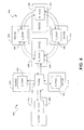
- FIG. 4 is a schematic diagram depicting representative communication devices and their associated fibre channel ports, with one of the communications devices being reassigned from a fabric configuration to an arbitrated loop configuration as facilitated by the control system of the present invention.
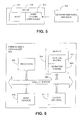
- FIG. 5 is a schematic diagram depicting a network communication device communicating with a network resource manager for implementing preferred functionality of the present invention.
- FIG. 6 is schematic diagram depicting a computer or processor-based system which may implement functionality of a preferred embodiment of the present invention.
- FIG. 7 is a flowchart depicting functionality of an embodiment of the control system of FIG. 6.
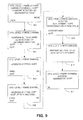
- FIG. 8 is a flowchart depicting functionality of an embodiment of the control system of FIG. 6.
- FIG. 9 depicts representative screens of a graphical user interface, which may be displayed to an operator when utilizing the control system of FIG. 6.
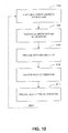
- FIG. 10 is a flowchart depicting functionality of an embodiment of the control system of FIG. 6.
- FIG. 11 depicts representative screens of a graphical user interface, which may be displayed to an operator when utilizing the control system of FIG. 6.
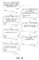
- FIG. 12 depicts representative screens of a graphical user interface, which may be displayed to an operator when utilizing the control system of FIG. 6.
- FIG. 13 depicts representative screens of a graphical user interface, which may be displayed to an operator when utilizing the control system of FIG. 6.
- FIG. 14 depicts representative screens of a graphical user interface, which may be displayed to an operator when utilizing the control system of FIG. 6.
- FIG. 15 depicts representative screens of a graphical user interface, which may be displayed to an operator when utilizing the control system of FIG. 6.
- fibre channel may support various topologies of intercommunicating network devices, with interconnections of the various devices being facilitated by ports.
- a representative point to point topology may be supported. More specifically, port 112 of a first communications device (not shown) communicates with port 114 of a second communications device (not shown) via link 116.
- Link 116 includes two unidirectional fibres, 118 and 120 respectively, which transmit in opposite directions, as well as their associated receivers and transmitters (not shown).
- fibres may comprise optical fiber and/or copper communications media.
- loop 200 includes ports, ports 212, 214, 216 and 218, that are serially interconnected via bidirectional fibres, e . g ., fibres 220, 222, 224, and 226.
- ports configured for being arranged in a arbitrated loop configuration are known as L_ports.
- FIG. 3 is representative of a fabric configuration.
- fabric configuration 300 includes ports, e.g., ports 312, 314, 316, and 318, which communicate with a fabric 320 via respective links, e.g., links 322, 324, 326, and 328.
- Fabric 320 is a non-blocking switch(es) that enables full communications connectivity between the various ports. From the perspective of one of the network devices, connectivity to one of the various ports of the fabric is a point-to-point connection, much like the connectivity depicted in FIG. 1. Therefore, ports connected to a fabric typically can be referred to as N_ports.
- FIG. 4 depicts a representative example of how the present invention may facilitate the multiple topology support characteristics of fibre channel.
- Port 406 is configured as an NL_port, which is adaptable for intercommunicating with network devices of either an arbitrated loop or a fabric, although other port types may be utilized.
- port 406 and its associated network device 408 are configured as part of fabric 402.
- network device 408 may communicate with devices 410, 412, and 414 via fabric 416. More specifically, device 410 is interconnected to the fabric via port 420, device 412 is interconnected to the fabric via port 422, and device 414 is interconnected to the fabric via port 424.
- arbitrated loop 404 which includes network devices 430, 432, and 434.
- the devices of the loop are interconnected via their respective ports 440, 442, and 444.
- device 408 currently is not communicatively coupled to the devices of the arbitrated loop 404.
- device 408 utilizes SCSI, e.g ., the device is a legacy storage device.
- Interfacing of device 408 with loop 404 is facilitated by a fibre channel controller (not shown).
- a fibre channel controller (not shown).
- each device is assigned an address, e.g., an arbitrated loop physical address (ALPA) which comprises an 8 bit value.
- ALPA arbitrated loop physical address
- Assignment of the ALPA associated with device 408 is facilitated by its fibre channel controller.
- the fibre channel controller utilizes the ALPA as the current ALPA of the device.
- Establishing the current ALPA is facilitated by address settings or ALPA settings of the fibre channel controller, with the ALPA settings corresponding to the preferred value for ALPA.
- the ALPA settings of the fibre channel controller become effective at power up and/or reset, thereby enabling the stored ALPA settings to influence the current ALPA only at either power up or reset.
- This methodology becomes problematic, however, when an operator desires to change the ALPA settings without performing a power up or reset of the fibre channel controller, as such a power up/reset may disrupt communications among other devices of the loop, for instance.
- preferred embodiments of the control system of the present invention substantially alleviate the aforementioned shortcoming of typically requiring that an operator perform a power up/reset of a fibre channel controller when changing ALPA settings.
- other enhancements also are provided, such as by enabling ALPA to be changed when a device is connected to a fabric topology.
- some previous methodologies incorrectly assume that the addressing mode of the fibre channel controller, i.e., hard, soft, or auto-assign, is not applicable to fabric and, therefore, does not provide for changing of the addressing mode while connected to fabric.
- an operator may be enabled to change ALPA even though no link is present. This functionality preferably is enabled while the operator is provided with an indication that the change was successfully accomplished. This is in direct contrast to some previous methodologies that report the absence of a link as a failure during the ALPA change procedure.
- the control system of the present invention preferably facilitates changing of ALPA settings at virtually anytime and in virtual disregard of the link state or topology of the fibre channel controller of the device.
- changing of ALPA of device 408 typically is required if that device is to be reassigned from fabric 402 to loop 404, for instance.
- fibre channel controller 500 of device 408 may be interfaced with a network management resource 502, which enables an operator to communicate with the fibre channel controller.
- network management resource 502 may include a computer or processor-based system (such a system is described in detail hereinafter) that, through the use of a graphical user interface (GUI), for example, enables information corresponding to the fibre channel controller to be viewed and/or changed by the operator.
- GUI graphical user interface
- resource manager 502 may include a display device for displaying the GUI and any associated information to the operator.
- control system of the present invention resides in fiber channel controller 500, although in other embodiments, the control system may reside on any other device or apparatus which may communicate with the fibre channel controller of interest.
- control system may, in some embodiments, be implemented by the network resource manager 502 (FIG. 5), for example.
- Control systems of the present invention may be implemented in hardware, software, firmware, or a combination thereof.
- the control system is implemented as a software package, which can be adaptable to run on different platforms and operating systems as shall be described further herein.
- a preferred embodiment of the control system which comprises an ordered listing of executable instructions for implementing logical functions, can be embodied in any computer-readable medium for use by or in connection with an instruction execution system, apparatus, or device, such as a computer-based system, processor-containing system, or other system that can fetch the instructions from the instruction execution system, apparatus, or device, and execute the instructions.
- any such instruction execution system, apparatus, or device can have a distributed architecture, where various components are situated remote from one another, but can intercommunicate so as to provide the required functionality.
- the control system also may be implemented with a distributed architecture, even when implemented as a software package.
- a "computer-readable medium" can be any means that can contain, store, communicate, propagate or transport the program for use by or in connection with the instruction execution system, apparatus, or device.
- the computer readable medium can be, for example, but is not limited to, an electronic, magnetic, optical, electro-magnetic, infrared, or semi-conductor system, apparatus, device, or propagation medium. More specific examples (a non-exhaustive list) of the computer-readable medium would include the following: an electrical connection (electronic) having one or more wires, a portable computer diskette (magnetic), a random access memory (RAM) (magnetic), a read-only memory (ROM) (magnetic), an erasable, programmable, read-only memory (EPROM or Flash memory) (magnetic), an optical fiber (optical), and a portable compact disk read-only memory (CDROM) (optical).
- an electrical connection electronic having one or more wires
- a portable computer diskette magnetic
- RAM random access memory
- ROM read-only memory
- EPROM or Flash memory erasable, programmable, read-only memory
- CDROM portable compact disk read-only memory
- the computer-readable medium could even be paper or another suitable medium upon which the program is printed, as the program can be electronically captured, via for instance, optical scanning of the paper or other medium, then compiled, interpreted, or otherwise processed in a suitable manner, if necessary, and then stored in a computer memory.
- control system 100 can implemented with any or a combination of the following technologies, which are each well known in the art: a discrete logic circuit(s) having logic gates for implementing logic functions upon data signals, an application specific integrated circuit (ASIC) having appropriate combinational logic gates, a programmable gate array(s) (PGA), a field programmable gate array (FPGA), etc.
- ASIC application specific integrated circuit
- PGA programmable gate array
- FPGA field programmable gate array
- FIG. 6 illustrates a computer or processor-based system 600 that may implement the control system 100 of the present invention.
- a computer system 500 generally comprises a processor 602 and a memory 604 with an operating system 606.
- the memory 604 may include volatile and/or nonvolatile memory elements, such as random access memory or read only memory.
- the processor 602 accepts instructions and data from memory 604 over a local interface 608, such as a bus(es).
- the system also includes an input device(s) 610 and an output device(s) 612. Examples of input devices may include, but are not limited to, a serial port, a scanner, or a local access network connection.
- Examples of output devices may include, but are not limited to, a video display, a Universal Serial Bus, or a printer port.
- this system may run any of a number of different platforms and operating systems, including, but not limited to, HP-uxTM, LinuxTM, UnixTM, Sun SolarisTM or Windows NTTM operating systems.
- the control system 100 of the present invention resides in memory 604 and is executed by the processor 602.
- each block of the flowchart represents a module segment or portion of code which comprises one or more executable instructions for implementing the specified logical function or functions.
- the functions noted in the various blocks may occur out of the order depicted in FIG. 7.
- two blocks shown in succession in FIG. 7 may, in fact, be executed substantially concurrently where the blocks may sometimes be executed in the reverse order depending upon the functionality involved.
- control system or method 100 of the present invention may be construed as beginning at block 702 where utilization of current address settings of a fibre channel device(s) is facilitated.
- information corresponding to desired address settings of one or more of the fibre channel devices is received.
- information corresponding to the desired address settings of the fibre channel devices is stored.
- a determination is made as to whether the board is being powered up. If it is determined that the board is being powered up, the process preferably proceeds to block 710 where the current address settings are replaced with the desired address settings of the fibre channel devices that previously were stored. Thereafter, the process may return to block 702, and then proceed as described hereinbefore.
- the process may continue to block 712 where a determination may be made as to whether a request for a change to the desired address settings has been received.
- the request may be in the form of an operator initiated reset of the board or other form of reinitialization of the fibre channel controller, e.g., warm boot, etc.. If it is determined that a request for changing to the desired address settings is received, the process may proceed to block 710 as described hereinbefore. If, however, a request for changing to the desired address settings is not received, the process may return to block 708.
- control systems of the present invention preferably distinguish between current ALPA and ALPA settings. Therefore, in contrast to previous methods, the present invention may enable a user to change ALPA settings without having to immediately reset the fiber controller of the device associated with those ALPA settings.
- Embodiments of the present invention may facilitate the functionality depicted in FIG. 8. Such functionality may be utilized, for example, when a device is connected to a loop topology.
- the functionality depicted in FIG. 8 may provide information in various modes, e.g ., a configure fiber channel information mode, a view fiber channel information mode, etc .
- the functionality depicted in FIG. 8 maybe representative of a preferred configure fiber channel information mode of operation.
- control system or method 100 depicted in FIG. 8 may be construed as beginning at block 802 where current address information may be provided to a user, such as via a display device. Such current address information may include current topology, current address, and current addressing mode of the fibre channel controller of interest. As depicted in block 804, address setting information also may be provided, e.g., address setting, addressing mode setting, etc. Thereafter, such as in block 806, an operator may be enabled to change the address setting information. After the operator approves of the address setting information, a determination may be made as to whether the address setting information previously provided in block 806 is to be utilized upon a current board reset or upon a next power cycle (block 808). Thereafter, such as depicted in block 810, the address setting information may be adopted as the current address upon reset, or, such as depicted in block 812, upon the next power cycle.
- information pertaining to the control system or method 100 depicted in FIG. 8 may be provided to an operator via a graphical user interface that provides one or more screens of information to the operator via a display device.
- the information provided by the various screens may be associated with one or more of the function blocks depicted in FIG. 8.
- information depicted in block (screen) 902 corresponds to block 802
- block 904 corresponds to block 804
- blocks 906 and 908 correspond to block 806,
- blocks 906 - 910 correspond to blocks 808 - 812.
- information provided to an operator via the GUI may be provided in various formats and/or in various configurations. For instance, in some embodiments, at least some of the information presented in the accompanying figures may not be provided to the operator, whereas, in other embodiments, other information may be provided. It is intended that all such embodiments be considered within the scope of the present invention.
- the method 100 may be construed as beginning at block 1002 where an operator may be provided with current address information. More specifically, when in a loop-connected configuration, for example, such current address information may include current link state, current topology, current address, and current addressing mode. Thereafter, such as depicted in block 1004, the operator may be provided with address setting information, such as address setting, and addressing mode setting. As depicted in blocks 1006 - 1008, additional information such as node, port, and board type information may be provided to the operator.
- the aforementioned information provided to an operator may be presented in a screen format via a display device.
- the representative screens 1102 - 1110 each relate to a corresponding block depicted in FIG. 10, i . e ., blocks 1002 - 1010.
- the functionality depicted therein also may be utilized, for example, when a device is connected to a fabric topology (when in configure fiber channel information mode).
- the current address information provided to the operator in block 802 preferably includes current topology and current address of the fibre channel controller of interest.
- the address setting information (block 804) provided preferably includes address setting and addressing mode setting.
- an operator may be enabled to change the address setting information. After the operator approves of the address setting information, a determination may be made as to whether the address setting information previously provided in block 806 is to be utilized upon a current board reset or upon a next power cycle (block 808). Thereafter, such as depicted in block 810, the address setting information may be adopted as the current address upon reset, or, such as depicted in block 812, upon the next power cycle.
- FIG. 12 Representative screens of information which correspond to the functionality described in relation to the fabric-connected configuration is shown in FIG. 12.
- block (screen) 1202 corresponds to block 802
- screen 1204 corresponds to block 804
- screens 1206 and 1208 correspond to block 806
- screen 1210 corresponds to blocks 808 and 812
- blocks 1212 and 1214 correspond to blocks 808 and 810.
- an attempt to change the addressing mode is recognized by the present invention.
- the present invention allows ALPA to be changed when the device is connected to fabric topologies.
- an operator may be provided with current address information (block 1002). More specifically, when in a fabric-connected configuration, for example, such current address information may include current link state, current topology, and current address. Thereafter, such as depicted in block 1004, the operator may be provided with address setting information, such as address setting, and addressing mode setting. As depicted in blocks 1006 - 1008, additional information such as node, port, and board type information may be provided to the operator.
- FIG. 13 Representative screens of information which correspond to the functionality described in relation to the fabric-connected configuration (when in view fiber channel information mode) is shown in FIG. 13. As depicted therein, the representative screens 1302 - 1310 each relate to a corresponding block depicted in FIG. 10, i.e., blocks 1002 - 1010.
- the functionality depicted therein also may be utilized, for example, when a device is not connected to a fibre channel topology (when in configure fiber channel information mode).
- the current address information provided to the operator in block 802 preferably includes current topology, current address, and current addressing mode of the fibre channel controller of interest.
- the address setting information (block 804) provided preferably includes address setting and addressing mode setting.
- an operator may be enabled to change the address setting information (block 806).
- FIG. 14 Representative screens of information which correspond to the functionality described in relation to the fabric-connected configuration is shown in FIG. 14.
- block (screen) 1402 corresponds to block 802
- screen 1404 corresponds to block 804
- screens 1406 and 1408 correspond to block 806
- screen 1410 corresponds to blocks 808 and 812
- blocks 1412 and 1414 correspond to blocks 808 and 810.
- screen 1410 and 1414 attempt to change the addressing mode and the ALPA, respectively, do not show the operator a failure merely because the device is not connected to a fabric topology.
- an operator may be provided with current address information (block 1002). More specifically, when in a non-connected configuration, for example, such current address information may include current link state, current topology, current address; and addressing mode. Thereafter, such as depicted in block 1004, the operator may be provided with address setting information, such as address setting, and addressing mode setting. As depicted in blocks 1006 - 1008, additional information such as node, port, and board type information may be provided to the operator.
- FIG. 15 Representative screens of information which correspond to the functionality described in relation to the fabric-connected configuration (when in view fiber channel information mode) is shown in FIG. 15. As depicted therein, the representative screens 1502 - 1510 each relate to a corresponding block depicted in FIG. 10, i . e ., blocks 1002 - 1010.
Landscapes
- Engineering & Computer Science (AREA)
- Computer Networks & Wireless Communication (AREA)
- Signal Processing (AREA)
- Small-Scale Networks (AREA)
- Bus Control (AREA)
Applications Claiming Priority (2)
| Application Number | Priority Date | Filing Date | Title |
|---|---|---|---|
| US834824 | 2001-04-13 | ||
| US09/834,824 US20020152308A1 (en) | 2001-04-13 | 2001-04-13 | Fibre channel deferred setup |
Publications (2)
| Publication Number | Publication Date |
|---|---|
| EP1249989A2 true EP1249989A2 (de) | 2002-10-16 |
| EP1249989A3 EP1249989A3 (de) | 2003-03-05 |
Family
ID=25267899
Family Applications (1)
| Application Number | Title | Priority Date | Filing Date |
|---|---|---|---|
| EP02252275A Withdrawn EP1249989A3 (de) | 2001-04-13 | 2002-03-27 | Ändern von Adresseninformationen der Netzvorrichtungen |
Country Status (3)
| Country | Link |
|---|---|
| US (1) | US20020152308A1 (de) |
| EP (1) | EP1249989A3 (de) |
| JP (1) | JP2002344461A (de) |
Families Citing this family (3)
| Publication number | Priority date | Publication date | Assignee | Title |
|---|---|---|---|---|
| US7596653B2 (en) * | 2004-11-08 | 2009-09-29 | Intel Corporation | Technique for broadcasting messages on a point-to-point interconnect |
| US7804822B2 (en) * | 2005-09-21 | 2010-09-28 | At&T Intellectual Property Ii, L.P. | Method and apparatus for detecting subscriber service address change |
| CN115632706B (zh) * | 2022-12-01 | 2023-03-14 | 苏州浪潮智能科技有限公司 | 一种fc链路管理方法、装置、设备及可读存储介质 |
Citations (1)
| Publication number | Priority date | Publication date | Assignee | Title |
|---|---|---|---|---|
| EP0713307A2 (de) * | 1994-11-08 | 1996-05-22 | Hewlett-Packard Company | Verfahren und Vorrichtung zur Struktur-Konfiguration in einem Lichtwellenleitersystem |
Family Cites Families (7)
| Publication number | Priority date | Publication date | Assignee | Title |
|---|---|---|---|---|
| US5954796A (en) * | 1997-02-11 | 1999-09-21 | Compaq Computer Corporation | System and method for automatically and dynamically changing an address associated with a device disposed in a fire channel environment |
| US6014383A (en) * | 1997-02-10 | 2000-01-11 | Compaq Computer Corporation | System and method for controlling multiple initiators in a fibre channel environment |
| US5944798A (en) * | 1997-02-19 | 1999-08-31 | Compaq Computer Corp. | System and method for arbitrated loop recovery |
| US6081847A (en) * | 1998-02-27 | 2000-06-27 | Lsi Logic Corporation | System and method for efficient initialization of a ring network |
| US6470026B1 (en) * | 1998-10-30 | 2002-10-22 | Agilent Technologies, Inc. | Fibre channel loop map initialization protocol implemented in hardware |
| US6167463A (en) * | 1999-04-08 | 2000-12-26 | Hewlett-Packard Company | Firm addressing for devices on a fibre channel arbitrated loop |
| US20030236745A1 (en) * | 2000-03-03 | 2003-12-25 | Hartsell Neal D | Systems and methods for billing in information management environments |
-
2001
- 2001-04-13 US US09/834,824 patent/US20020152308A1/en not_active Abandoned
-
2002
- 2002-02-26 JP JP2002049714A patent/JP2002344461A/ja not_active Withdrawn
- 2002-03-27 EP EP02252275A patent/EP1249989A3/de not_active Withdrawn
Patent Citations (1)
| Publication number | Priority date | Publication date | Assignee | Title |
|---|---|---|---|---|
| EP0713307A2 (de) * | 1994-11-08 | 1996-05-22 | Hewlett-Packard Company | Verfahren und Vorrichtung zur Struktur-Konfiguration in einem Lichtwellenleitersystem |
Also Published As
| Publication number | Publication date |
|---|---|
| JP2002344461A (ja) | 2002-11-29 |
| EP1249989A3 (de) | 2003-03-05 |
| US20020152308A1 (en) | 2002-10-17 |
Similar Documents
| Publication | Publication Date | Title |
|---|---|---|
| US11394607B2 (en) | Method and system for network configuration | |
| US6498598B2 (en) | Imaging device system, control method for the system, imaging device, control device, control method for the imaging device, control method for the control device, and storage medium | |
| US6925492B2 (en) | Method and apparatus for automatic configuration of a cluster of computers | |
| US8171179B2 (en) | Apparatus supporting plurality of interfaces and method of setting up network connection of the same | |
| US11989100B2 (en) | Information backup method and related device | |
| GB2363040A (en) | Automatic negotiation of data rates in a Fibre Channel Arbitrated Loop (FCAL) | |
| JP2000269990A (ja) | 通信制御装置 | |
| EP1249989A2 (de) | Ändern von Adresseninformationen der Netzvorrichtungen | |
| US6738843B2 (en) | Method and system for generating multiple self-ID packets on the 1394 bus using a standard PHY chip | |
| JP2021019348A (ja) | ユーザの要求に基づいて効率的にネットワークを管理するためのトラフィック管理方法及び装置 | |
| CN113220613B (zh) | WiFi无线网络适配器及其控制方法 | |
| CN112953824B (zh) | 一种链路聚合的配置方法及装置 | |
| CN113163403B (zh) | WiFi无线网络适配器及其控制方法 | |
| US7454513B2 (en) | Interface link layer device for long delay connections | |
| US20240214308A1 (en) | Data Transmission Method, System, and Apparatus | |
| KR100346683B1 (ko) | Ieee1394를지원하는컴퓨터에서의주변기기연결장치및그방법 | |
| EP1033658A2 (de) | Übertragungsvorrichtung mit Mittel zur Zuweisung von einer alternativen Bestimmungsinformation zu jeder Funktionseinheit, und Übertragungssystem mit zwei solchen Übertragungsvorrichtungen | |
| CN1609819B (zh) | 一种计算机外围设备接口的测试方法 | |
| CN101159558B (zh) | 一种获取单板标识的方法和装置以及一种单板 | |
| JPH01135150A (ja) | ネットワークのノードアドレス設定方式 | |
| EP4117233B1 (de) | Netzwerkkonfigurationsverfahren, endgerät, system und speichermedium | |
| US20060271706A1 (en) | Method, apparatus, and computer program product for requesting deterministic virtual address identifiers for nodes in a fibre channel network | |
| JP2891956B2 (ja) | Atmネットワークシステム | |
| CN108132900A (zh) | 转接设备、远程通信系统以及数据传输方法 | |
| CN120281724A (zh) | 传输协议的传输单元大小调整方法、装置、设备及介质 |
Legal Events
| Date | Code | Title | Description |
|---|---|---|---|
| PUAI | Public reference made under article 153(3) epc to a published international application that has entered the european phase |
Free format text: ORIGINAL CODE: 0009012 |
|
| AK | Designated contracting states |
Kind code of ref document: A2 Designated state(s): AT BE CH CY DE DK ES FI FR GB GR IE IT LI LU MC NL PT SE TR |
|
| AX | Request for extension of the european patent |
Free format text: AL;LT;LV;MK;RO;SI |
|
| PUAL | Search report despatched |
Free format text: ORIGINAL CODE: 0009013 |
|
| AK | Designated contracting states |
Kind code of ref document: A3 Designated state(s): AT BE CH CY DE DK ES FI FR GB GR IE IT LI LU MC NL PT SE TR Designated state(s): AT BE CH CY DE DK ES FI FR GB GR IE IT LI LU MC NL PT SE TR |
|
| AX | Request for extension of the european patent |
Extension state: AL LT LV MK RO SI |
|
| 17P | Request for examination filed |
Effective date: 20030728 |
|
| AKX | Designation fees paid |
Designated state(s): DE FR GB |
|
| 17Q | First examination report despatched |
Effective date: 20031113 |
|
| STAA | Information on the status of an ep patent application or granted ep patent |
Free format text: STATUS: THE APPLICATION IS DEEMED TO BE WITHDRAWN |
|
| 18D | Application deemed to be withdrawn |
Effective date: 20050404 |