EP1249982A2 - Vorrichtung und Verfahren zur Datenkommunikation, insbesondere zur Parametrisierung und Fernüberwachung von Heizungsanlagen - Google Patents
Vorrichtung und Verfahren zur Datenkommunikation, insbesondere zur Parametrisierung und Fernüberwachung von Heizungsanlagen Download PDFInfo
- Publication number
- EP1249982A2 EP1249982A2 EP02004209A EP02004209A EP1249982A2 EP 1249982 A2 EP1249982 A2 EP 1249982A2 EP 02004209 A EP02004209 A EP 02004209A EP 02004209 A EP02004209 A EP 02004209A EP 1249982 A2 EP1249982 A2 EP 1249982A2
- Authority
- EP
- European Patent Office
- Prior art keywords
- data
- protocol
- system computer
- protocol converter
- connection
- Prior art date
- Legal status (The legal status is an assumption and is not a legal conclusion. Google has not performed a legal analysis and makes no representation as to the accuracy of the status listed.)
- Withdrawn
Links
Images

Classifications
-
- H—ELECTRICITY
- H04—ELECTRIC COMMUNICATION TECHNIQUE
- H04L—TRANSMISSION OF DIGITAL INFORMATION, e.g. TELEGRAPHIC COMMUNICATION
- H04L69/00—Network arrangements, protocols or services independent of the application payload and not provided for in the other groups of this subclass
- H04L69/08—Protocols for interworking; Protocol conversion
-
- H—ELECTRICITY
- H04—ELECTRIC COMMUNICATION TECHNIQUE
- H04L—TRANSMISSION OF DIGITAL INFORMATION, e.g. TELEGRAPHIC COMMUNICATION
- H04L12/00—Data switching networks
- H04L12/28—Data switching networks characterised by path configuration, e.g. LAN [Local Area Networks] or WAN [Wide Area Networks]
- H04L12/2803—Home automation networks
- H04L12/283—Processing of data at an internetworking point of a home automation network
- H04L12/2836—Protocol conversion between an external network and a home network
-
- H—ELECTRICITY
- H04—ELECTRIC COMMUNICATION TECHNIQUE
- H04L—TRANSMISSION OF DIGITAL INFORMATION, e.g. TELEGRAPHIC COMMUNICATION
- H04L43/00—Arrangements for monitoring or testing data switching networks
-
- H—ELECTRICITY
- H04—ELECTRIC COMMUNICATION TECHNIQUE
- H04L—TRANSMISSION OF DIGITAL INFORMATION, e.g. TELEGRAPHIC COMMUNICATION
- H04L51/00—User-to-user messaging in packet-switching networks, transmitted according to store-and-forward or real-time protocols, e.g. e-mail
- H04L51/06—Message adaptation to terminal or network requirements
- H04L51/066—Format adaptation, e.g. format conversion or compression
-
- H—ELECTRICITY
- H04—ELECTRIC COMMUNICATION TECHNIQUE
- H04L—TRANSMISSION OF DIGITAL INFORMATION, e.g. TELEGRAPHIC COMMUNICATION
- H04L67/00—Network arrangements or protocols for supporting network services or applications
- H04L67/01—Protocols
- H04L67/12—Protocols specially adapted for proprietary or special-purpose networking environments, e.g. medical networks, sensor networks, networks in vehicles or remote metering networks
-
- H—ELECTRICITY
- H04—ELECTRIC COMMUNICATION TECHNIQUE
- H04L—TRANSMISSION OF DIGITAL INFORMATION, e.g. TELEGRAPHIC COMMUNICATION
- H04L69/00—Network arrangements, protocols or services independent of the application payload and not provided for in the other groups of this subclass
- H04L69/16—Implementation or adaptation of Internet protocol [IP], of transmission control protocol [TCP] or of user datagram protocol [UDP]
-
- H—ELECTRICITY
- H04—ELECTRIC COMMUNICATION TECHNIQUE
- H04L—TRANSMISSION OF DIGITAL INFORMATION, e.g. TELEGRAPHIC COMMUNICATION
- H04L9/00—Cryptographic mechanisms or cryptographic arrangements for secret or secure communications; Network security protocols
- H04L9/40—Network security protocols
-
- H—ELECTRICITY
- H04—ELECTRIC COMMUNICATION TECHNIQUE
- H04M—TELEPHONIC COMMUNICATION
- H04M11/00—Telephonic communication systems specially adapted for combination with other electrical systems
- H04M11/06—Simultaneous speech and data transmission, e.g. telegraphic transmission over the same conductors
-
- H—ELECTRICITY
- H04—ELECTRIC COMMUNICATION TECHNIQUE
- H04L—TRANSMISSION OF DIGITAL INFORMATION, e.g. TELEGRAPHIC COMMUNICATION
- H04L12/00—Data switching networks
- H04L12/28—Data switching networks characterised by path configuration, e.g. LAN [Local Area Networks] or WAN [Wide Area Networks]
- H04L12/2803—Home automation networks
- H04L2012/2847—Home automation networks characterised by the type of home appliance used
- H04L2012/285—Generic home appliances, e.g. refrigerators
-
- H—ELECTRICITY
- H04—ELECTRIC COMMUNICATION TECHNIQUE
- H04L—TRANSMISSION OF DIGITAL INFORMATION, e.g. TELEGRAPHIC COMMUNICATION
- H04L51/00—User-to-user messaging in packet-switching networks, transmitted according to store-and-forward or real-time protocols, e.g. e-mail
-
- H—ELECTRICITY
- H04—ELECTRIC COMMUNICATION TECHNIQUE
- H04L—TRANSMISSION OF DIGITAL INFORMATION, e.g. TELEGRAPHIC COMMUNICATION
- H04L69/00—Network arrangements, protocols or services independent of the application payload and not provided for in the other groups of this subclass
- H04L69/30—Definitions, standards or architectural aspects of layered protocol stacks
- H04L69/32—Architecture of open systems interconnection [OSI] 7-layer type protocol stacks, e.g. the interfaces between the data link level and the physical level
- H04L69/322—Intralayer communication protocols among peer entities or protocol data unit [PDU] definitions
- H04L69/329—Intralayer communication protocols among peer entities or protocol data unit [PDU] definitions in the application layer [OSI layer 7]
Definitions
- the invention relates to a device and a method for data communication between a system computer and building technology equipment for flexible and convenient parameterization and remote monitoring of the facilities, whereby an existing communication infrastructure can be used, to reduce the wiring effort.
- Modern heating systems require a variety of parameters for their operation, which are set when the system is started up and monitored during operation Need to become.
- large heating systems in particular there is a large number from different facilities, for example on a company site distributed across different locations.
- the data from burners, Heat pumps, heat meters and a variety of temperature sensors for the Control of a heating system Usually for the data transmission connection all of these facilities use a house or field bus.
- Such a bus system which is installed, for example, within a building is necessary for the automatic control of a heating system Data is transferred between the various facilities of the plant.
- a large number of such, mostly manufacturer-dependent bus systems are known.
- a house bus system for example for networking a multi-boiler system, is required also special wiring, which is usually a considerable effort the building installation means. Furthermore, special maintenance and configuration terminals required for connection to the respective house bus system. By the large number of different house bus systems can be a great deal of extra work in the cabling and in the devices to be kept ready. On the other Side is already a communication infrastructure in most office and company buildings, mostly in the form of telephone and data transmission cabling, available.
- An object of the present invention is an apparatus and a method for data communication between facilities, especially heating, Air conditioning and / or cooling systems, and a system computer to create a flexible and convenient maintenance, parameterization and remote monitoring of the facilities allows.
- facilities especially heating, Air conditioning and / or cooling systems, and a system computer to create a flexible and convenient maintenance, parameterization and remote monitoring of the facilities allows.
- an existing communication infrastructure should be used can be used to make the effort for the to reduce the cabling required and cost-effective data communication to enable.
- a device for data communication in particular for parameterization and remote monitoring of heating systems, a system computer, at least one building technology facility, a protocol converter and have a bus system.
- a system computer at least one building technology facility, a protocol converter and have a bus system.
- the system computer is for the transmission of data according to a first data transmission protocol suitable.
- the system computer can use software for parameterization and have remote monitoring of the facilities.
- the system computer can be in a central control center for the monitoring and remote maintenance of heating systems be arranged. However, it can also be a mobile device that is used on site for parameterization and maintenance of a heating system.
- the software used on the system computer, the user interface for the Operation and the type of data transmission can be the same in both cases his.
- the devices are for the transmission of data according to a second data transmission protocol suitable. By transferring data between facilities and the system computer, the devices can be parameterized and be monitored.
- the devices of the device can be spatially integrated, for example, be arranged in a built-in frame or a built-in cabinet or they can be in different locations, for example in a building distributed, located. There will be a variety of different facilities can be parameterized and monitored in this way.
- the protocol converter converts data from the first data transmission protocol into Data of the second data transmission protocol and vice versa. He is with the system computer connected for example via a data transmission connection.
- the Protocol converter converts the data received from the system computer of the first Data transmission protocol in data of the second data transmission protocol around. On the other hand, the protocol converter converts from the facilities received data of the second data transmission protocol in data of the first Data transfer protocol.
- the protocol converter can be spatially independent Be device or with other devices of the device in a mounting frame or built-in wardrobe.
- the protocol converter connects this Bus system with the system computer and takes the electrical and logical adaptation between the bus system and the data transmission connection to the system computer in front.
- the protocol converter can be used for a variety of different purposes Bus systems and data transmission connections can be designed. It enables a simple, flexible and modular connection of the system computer to different Facilities and bus systems and allows a uniform structure of the system computer and its software.
- the bus system connects the devices of the device and the protocol converter.
- the bus system can transfer data between the individual devices the building technology with each other and to the protocol converter.
- the bus participants can, for example, transmit measured values, commands for Control and regulation of the systems exchange and messages for diagnostic purposes to ship.
- the devices that can be connected to the bus system can Heating, air conditioning and / or cooling systems.
- heat meters and / or temperature sensors can be connected to the bus system.
- the one at that Devices connected to the bus system can be easily and conveniently operated parameterized, monitored and / or maintained on the system computer.
- the special and locally limited bus system can easily convert protocol converters Way to be connected to the general communication infrastructure.
- a special cabling between the devices or the bus system and the System computer that is located, for example, far from the heating systems in a central control center is not necessary.
- Through the protocol conversion can the system computer with different bus systems and different Facilities are operated.
- the structure and function of the system computer can be the same for different heating systems, for example.
- the bus system can be a house or field bus in various designs his.
- the second data transmission protocol can be a LON protocol.
- the LON bus participants can communicate with each other and exchange data.
- a protocol converter according to the invention can also include additional analog or digital ones Inputs and outputs for direct connection of devices without the bus system exhibit.
- the digital inputs can, for example, state yon connected devices.
- the analog inputs can preferably be used for Acquisition of measured values, e.g. by connecting temperature sensors his.
- Through the outputs, for example relay outputs, can be connected Devices are controlled.
- Through the direct inputs and outputs of the protocol converter can devices that do not have a bus interface from the invention Device for data communication monitored and controlled become.
- the protocol converter can function as a virtual one on the bus system affiliated facility take over like the other facilities is remotely monitored, parameterized and controlled by the system computer.
- the first data transmission protocol can be a protocol based on the Internet protocol Be IP.
- the Simple Network Management Protocol SNMP the Hypertext Transport Protocol HTTP, the Transport Control Protocol TCP or the LonWorks Network Protocol possible as transport protocols.
- SNMP Simple Network Management Protocol
- HTTP Hypertext Transport Protocol
- TCP Transport Control Protocol
- LonWorks Network Protocol possible as transport protocols.
- the protocol converter can be predetermined at predetermined time intervals Query data from the facilities, save, send to the system computer and / or have it ready to be queried by the system computer.
- the predetermined data and the specified time intervals for querying them during configuration of the protocol converter system-specific by the system builder or - operator can be set. For example, when configuring the protocol converter a list of the facilities and data to be queried is created. This data can include system data such as the setting of the loading service and configuration data of the devices, fault messages, process data, Maintenance data and / or measurement data from, for example, heat meters.
- the Protocol converter can save the requested data and, for example, for Have the query ready from the system computer.
- the protocol converter can also work independently Send data to the system computer without being prompted by the system computer waiting.
- the facilities can also send messages to the protocol converter independently, which are forwarded from the protocol converter to the system computer or temporarily stored and be kept ready for inquiry by the system computer.
- the protocol converter serves to connect all units connected to the bus system with the system computer. It collects those sent from the facilities or queried data, evaluates it and forwards it to the system computer.
- the protocol converter can store the data requested by the devices or have sent data. For example, in this memory the configuration data and operating states of the facilities, maintenance, Fault or diagnostic messages can be saved. The stored data are available for a query from the system computer. The ones requested by the system computer Data can thus be transferred directly to the system computer, without first asking the appropriate institution to determine the desired data must be done. The individual data can also be combined and in larger data packets are transferred to the system computer, which increases efficiency the data transmission to the system computer increases and the costs for the data transmission can reduce.
- the protocol converter can receive data received from the system computer for a certain device are determined, via the bus system to the corresponding Send facility.
- the protocol converter receives commands, for example for a heating system and forwards it to the appropriate facility.
- commands can advantageously also be in one data packet the first data transmission protocol together from the system computer to the Protocol converter are transmitted.
- the protocol converter can do the different Separate commands of the received data packet and send them to the forward individual facilities. In the opposite direction, for example many individual measured values from different devices to a data packet be combined and via the first data transfer protocol from the protocol converter be transferred to the system computer. In this way, the Effort for data transmission between the system computer and protocol converter reduce significantly.
- the data transmission between the protocol converter and the system computer can, for example secured against unauthorized eavesdropping using data encryption become. It can also query data and transmit commands by exchanging keys or access codes against unauthorized use be secured. Furthermore, only one can access, for example determined system computer specified when configuring the protocol converter, be allowed on the protocol converter. That way you can only registered and authorized systems or users have access to the facilities gain.
- the protocol converter can activate a predetermined connection and / or send a specified message if one of the devices or maintenance message.
- the protocol converter can send a fax, an email, an SMS message or a voice message to a predetermined Send recipient. If one of the facilities malfunctions or Maintenance message requested from or received by the protocol converter the protocol converter can try to connect to the system computer to build up to forward the message. This is for various reasons not possible, for example because of the system computer or the data transmission connection to the system computer has failed or has a fault the protocol converter a predetermined after a certain number of attempts Activate emergency connection.
- the protocol converter can, for example Establish a connection to another system computer or a given fax, send an email, a voice message or an SMS message.
- This message can be used by the operating personnel responsible for reporting the fault Establishment and / or the malfunction of the data transmission connection or the malfunction of the system computer in the control center. Can also by one Fax, email or text message a predetermined user from that Be informed of the problem. This is especially true for the operators of smaller ones Systems that do not have a control center permanently staffed are interesting.
- the operating personnel can be inexpensive and simple, for example at home, be alerted.
- the connection between the protocol converter and the system computer can according to the invention via an analog and / or digital telephone connection.
- the connection can be, for example, an analog modem, a GSM modem or have an ISDN modem.
- the data transmission connection can be made via a private and / or a public network is inexpensive.
- the connection between the protocol converter and the system computer can exist permanently or set up and taken down as required.
- the establishment and dismantling of the connection can be done both from the protocol converter and from the system computer.
- the modem of the protocol converter dials a local dial-in number of an Internet provider and provides one temporary internet connection to the system computer. That way you can arbitrarily arranged systems (protocol converter and facilities) inexpensive communicate with the system computer and is monitored and controlled by it become. The connection costs when operating from across the globe Investments can be reduced in this way.
- the protocol converter asks the facilities at predetermined times Distances and determines the predetermined data for transmission to the System computer. After all predetermined data have been determined, the Protocol converter establish a connection to the system computer, the data transmit together and terminate the connection to the system computer. On the on the other hand, the system computer can also connect to the protocol converter establish, query the required data from it and terminate the connection.
- connection from the system computer to the protocol converter can also be used a call-back procedure.
- the system computer sends a short signal or a callback request to the protocol converter if he wants to transfer or query from this data.
- the protocol converter then calls back a specified callback number to establish a data transmission connection to build up to the system computer. Because the actual data transfer connection always set up from the protocol converter to the system computer a foreign system cannot transfer data to the protocol converter or query from this. Unauthorized access to the protocol converter is prevented and the security of the device for data communication is elevated.
- the protocol converter and the system computer for example, have one or more RS-232 interfaces. In this way can simply use analog or ISDN modems to set up the data transmission connection used between the protocol converter and the system computer become.
- Protocol converters and system computers can also use a null modem cable or via an optical interface, in particular an Optolink interface, can be directly connected to each other. This is especially true for one On-site diagnosis and maintenance by customer service are an advantage.
- the system computer For example, a suitable portable computer that is nearby the heating system is connected to a protocol converter.
- the invention Device can be used both in the control center and on the portable Computer on site the same software for parameterization and monitoring used by heating systems.
- Another possibility for the data transmission connection between system computers and protocol converter consists in the direct connection of both devices a data network LAN.
- the protocol converter can use a LAN couplers can be connected to an Ethernet.
- the system computer can a standard Ethernet network connection is connected to the data transmission network become. This enables a simple and inexpensive connection via one possibly already existing data transmission network.
- the system computer can connect to at predetermined time intervals build up the protocol converter and query predetermined data.
- the predetermined Data was previously requested from the facilities by the protocol converter and cached.
- the system computer can in this way by a only query a larger amount of data all over the bus system with that Record devices connected to the protocol converter. Establishing a connection to every single facility is not necessary. In this way, the data transfer costs reduced and the structure of the system computer can be simplified.
- the connection can also be established using the callback procedure, in which the Protocol converter after receiving a callback message a given callback number selects and establishes the connection to the system computer.
- the system computer can establish a connection to the protocol converter and Send data to the protocol converter for a specific device. The connection can then be dismantled immediately.
- the protocol converter evaluates the received data and forwards commands to the corresponding ones Facilities continue.
- the system computer can also connect to the protocol converter build and data from a particular facility from that Query / receive protocol converter.
- the protocol converter can, if the requested Data does not already exist in the memory, the appropriate facility Contact via the bus system, determine the requested data and send it to the Transfer system computer.
- the protocol converter enables a logical connection between the facilities of the dss bus system and the system computer.
- the Data communication takes place between the facilities and the system computer via the protocol converter instead.
- the protocol converter can access the Regulate facility data, distribute or bundle / combine data and commands and control the connection to the system computer.
- the system computer can also establish connections to several protocol converters and transmit and receive data to and from multiple devices. It can send data for certain devices to the respective protocol converter send and / or data from certain facilities by the respective protocol converters receive. For this purpose, the system computer sends data for, for example a specific device to the protocol converter connected to the same bus system how the particular facility is connected.
- the system computer can have a database which contains the configuration, commissioning, Maintenance and operating data of facilities and / or protocol converters contains.
- fault and maintenance messages in the Database can be saved.
- the database can, for example, control, configuration and operating data of the individual facilities. Can continue Process and measurement data, for example from heat meters or temperature sensors, to be recorded.
- the database can also advantageously contain system data the protocol converter, such as the type of connected Bus system, a list of connected devices and / or information about used modem types and their control configurations.
- system data the protocol converter such as the type of connected Bus system, a list of connected devices and / or information about used modem types and their control configurations.
- the database can, for example, show the current state of the monitoring heating systems included. The operating personnel can check the current Check condition and, if necessary, measures to remedy faults initiate. Furthermore, the database can reference data and / or commissioning or Service logs for the monitored equipment (facilities) included.
- the system computer can send a predetermined message if from a the equipment has a specific fault or maintenance message.
- the system computer can send a fax, a voice message, an email or a SMS message to another system computer, for example in another Control center, and / or send to one or more predetermined operators, to inform them of the receipt of a fault or maintenance message.
- the forwarding of the messages can be carried out according to a specified processing plan, in which the corresponding services are entered.
- the machining plan can be time and system specific for each facility or for a group of Facilities include a duty and / or service plan that indicates what type by notification at what time for which facility for a specific action leads, e.g. forward as SMS message.
- the actions to be carried out can simply adapted to the duty rosters of the operating personnel through the processing plan become.
- the system computer can also carry out predefined tasks according to a Execute definable time schedule, for example, to determine specific plant values Monitor heating systems.
- the database of the system computer can be accessed via an Internet server and / or a WAP server. You can use the data on the system computer a WAP-enabled mobile phone or a conventional Internet browser accessed via the Internet from a suitably equipped personal computer become. For example, the operating and maintenance status of the monitoring devices on a web server for querying via the Internet to be provided. This is especially true for the operating personnel of smaller ones Systems that are not always in the control center are an advantage. The responsible one Maintenance personnel can, for example, send an SMS message a particular disorder is made known. Correcting this problem can be accessed by operating personnel from home via the Internet and the web server or a WAP-compatible mobile phone. A nightly arrival of the operating staff to the control center can be avoided.
- control centers and several system computers each have connections to the Set up protocol converters and / or receive data from the protocol converters or send data to the protocol converter.
- the system computers can communicate with each other over the Internet. That way it can be easy a distributed system with several system computers can be realized.
- the system computers can be arranged in several control centers, for example. Can too a system computer can be arranged in a control center and another system computer in the form of a portable computer for on-site diagnosis.
- the system computers can be connected via the Internet and messages change.
- One of the system computers can have a central database.
- the other system computers can report data changes to this central database and / or compare their own database with the central database. This is particularly so for a large system with several system computers in a large control center or advantageous for several control centers and can be used for data backup and / or Maintaining data consistency when multiple users / systems access the same data are used.
- the system computer which is the central database can automatically compare the databases of the individual Activate system computer.
- a method for data communication can be at least one of the following Have steps: transmission of data according to a first data transmission protocol between a system computer and a protocol converter; conversion the data of the first data transmission protocol in data of the second data transmission protocol and vice versa to the protocol converter; and transmission of data according to the second data transmission protocol between the protocol converter and at least one facility.
- the device according to the invention and the method according to the invention for data communication between a system computer and at least one facility via a protocol converter enables simple and flexible setup of complex heating, air conditioning and cooling systems.
- the parameterization and Remote monitoring of the facilities can be done in the same way from a system computer carried out in the control center or a mobile system computer on site become.
- the protocol converter enables the use of a wide variety of bus systems for networking the facilities and for operating a data transmission connection to the system computer via a possibly already existing one Communications infrastructure. By caching the data in the Protocol converters can be used in the case of a telephone dial-up connection to the system computer the connection costs are kept low.
- the database of the system computer enables the operating personnel to have immediate access to current ones Operating and configuration data of the facilities to be managed.
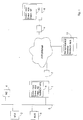
- the facility to be monitored are in this embodiment is a first heating system HZ-A 2, a second heating system HZ-B 3 and a heat meter WZ 4.
- the devices 2, 3, 4 are connected to the bus system 5.
- the bus system 5 is For example, a LON house bus that is used in a building to control the Building technology is installed.
- the protocol converter 1 is both with the bus system 5 and with a modem 7 connected.
- the protocol converter can, for example, a LON bus interface, an optical interface (Optolink interface) and an RS-232 interface exhibit.
- the modem 7 can be an analog telephone modem or an ISDN modem.
- the modem 7 is via standard telephone wiring connected to a private or public telephone network. Instead of a wired connection, a wireless connection can also be used be provided via a GSM modem.
- the modem 7 is controlled by the protocol converter 1.
- the protocol converter 1 also has a memory 6 for storing queried data from the connected devices 2, 3, 4 and for storing received messages from devices 2, 3, 4 on.
- a protocol converter 1 can also have additional analog or digital inputs and outputs for the direct connection of devices without a bus interface. For example, the states of connected devices can be entered through the inputs or measured values are recorded. The outputs, e.g. Relay outputs can be used Control of connected devices can be used. This enables operation of relatively simple devices such as temperature sensors that do not have their own bus interface exhibit. Through the inputs and outputs of the protocol converter 1 can these devices from the inventive device for data communication be monitored and controlled. The protocol converter 1 takes over Function of a virtual device, like the other devices from the system computer 8 is monitored, parameterized and set and the control of the directly connected devices.
- the protocol converter 1 asks predetermined time intervals Data from the devices 2, 3, 4 connected via the bus system 5 from and stores them in the memory 6 provided for this purpose.
- the memory shown in FIG Examples were data from the first heating system HZ-A 2, the second heating system HZ-B 3 and the heat meter WZ 4 queried and saved.
- the Cyclic data requests can take place every 10 minutes, for example.
- the queried Data can include, for example, the operating and configuration states of the queried Facilities included. In the example shown in Fig. 1, these were Data queried by facilities 2, 3, 4, for example, at 7.55 a.m.
- the saved Data is saved by the protocol converter 1 in the memory 6 for querying kept ready by the system computer 8.
- the system computer 8 for example, connects to the every hour Protocol converter 1 and causes the transfer of the protocol converter 1 stored data.
- an analog to this or an ISDN modem 9 connected to the system computer 8 and the telephone network.
- a system computer 8 can also have several modems 9 in order to maintain several connections to protocol converters at the same time.
- the system computer 8 causes modem 9, for example, to make a dial-up connection to the Build modem 7 and protocol converter 1. This can be done in predetermined at intervals or as required.
- the callback procedure can also be used to establish a secure connection can be used between protocol converter 1 and system computer 8.
- the connection can be used as a direct modem connection between modems 7, 9 (e.g. via the V.34 or V.90 standard) as well as via an internet connection respectively.
- the modem 7 dials a local dial-in number, for example Internet providers and connects to the system computer 8, the is connected to the Internet via modem 9 or a LAN connection.
- the data stored in the protocol converter 1 transferred to the system computer 8 and stored there in a database 10.
- Termination of data transmission can reduce the connection costs be dismantled.
- connection is established by the system computer 8 to the protocol converter 1, for example at hourly intervals.
- the Data stored in the database 10 were, for example, at 8:00 a.m. Transfer protocol converter 1 to system computer 8.
- the protocol converter 1 has these data are queried by the devices 2, 3, 4, for example, at 7.55 a.m.
- a next regular data transfer between protocol converter 1 and System computer 8 would take place at 9:00 a.m. in the example shown.
- the protocol converter 1 Upon receipt of one According to the invention, the protocol converter 1 should immediately report a fault Message to the system computer 8 are transmitted and not on the next query the data are maintained by the system computer 8. In the example shown the next data transmission initiated by the system computer 8 would be at 9 a.m. occur.
- the protocol converter 1 controls the modem 7 for a connection to build up to the system computer 8 and forward the received message. This connection between protocol converter 1 and system computer 8 cannot can be set up, the protocol converter 1 can, for example, after elapse attempts to establish a connection to a predetermined time other system computers to send the received message to a system computer forward.
- the system computer 8 can receive the message according to the processing plan, for example in the form of a fax, an email or forward an SMS message to the operating personnel when the control center goes to Time of receipt of the message is not busy. This connection comes the protocol converter 1 also fails in the further attempts a given message.
- the fax machine 11 can, for example in a control center or at home with a responsible operator. The In this way, the responsible person can be immediately informed of the disturbance received be notified in one of the facilities, although none at this time Connection between protocol converter 1 and system computer 8 is possible.
- protocol converter 1 and system computer 8 can be used for many others Species are linked together and exchange data. For example can both be connected directly to a computer network (LAN) or they can be connected to each other directly via a null modem. There are other embodiments are also conceivable in which the Internet or other data transmission media can be used.
- the operating and configuration data of the devices 2, 3, 4 can be obtained from the operating personnel in the control center directly by accessing the database 10 of the system computer 8 checked and checked without permanent There is a connection to the facilities 2, 3, 4 to be maintained and monitored got to.
- the given in this example are given Time intervals are only one possible example of a configuration of the invention Device and can be adapted to the requirements become.
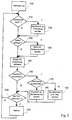
- a step 100 the stored system configuration of the Protocol converter evaluated and the protocol converter is initialized.
- a connected modem can be configured and the house bus system being checked.
- step 110 it is checked whether commands of the system computer 8 for the Protocol converter 1 connected devices 2, 3, 4 were received. in the If such commands are received, they are processed in a step 120 and forwarded to the corresponding devices via the bus system 5.
- commands that are connected to all are also possible Devices must be forwarded via the bus system 5 (broadcast).
- the system computer 8 can of course also send commands to the protocol converter 1 send yourself. These are to be evaluated by the protocol converter 1. Examples. for example, the telephone number to be dialed for an emergency connection can be dialed in this way to be changed.
- step 130 the protocol converter 1 checks whether there is a data request from the system computer 8 is present. There is a request for data from connected facilities before, the requested data are sent to the system computer 8 in step 140. If no data is to be sent to the system computer 8, the method goes directly to step 150 branched.
- step 150 the predetermined ones set in the configuration data are Data queried by a device 2, 3, 4.
- a corresponding command is used for this according to the second data transmission protocol to device 2, 3, 4 sent over the bus system 5.
- the facility mentioned reports with the requested data back via the bus system 5.
- the received in this way Data are stored in the memory 6 of the protocol converter 1.
- step 160 it is checked whether on the basis of the received data or on the basis of received messages from the devices to be monitored 2, 3, 4 a Emergency message to be sent to the system computer 8.
- step 170 tries to establish a connection to the system computer 8. Possibly is an attempt to establish a connection after a specified time Repeat several times (e.g. 10 times). You can also try a connection to build another system computer 8.
- the Protocol converter 1 in step 180 according to the first data transmission protocol a message, e.g. an emergency message of the appropriate content to the system computer 8.
- This emergency message can be the received message from the malfunctioning facility and / or the reason why the emergency message was sent.
- the data transmission to the system computer 8 can be carried out using an acknowledgment process be carried out in which the respective receiving side receives a Message acknowledged.
- Step 170 branches to step 190.
- the protocol converter 1 a predetermined emergency connection is activated and a predetermined message, for example a fax sent.
- This fax can be the reason for the emergency notification and a description of the present fault in the connection to the system computer 8 contain.
- step 200 it is checked whether the determined data from all devices to be queried 2, 3, 4 already exist. If data from facilities 2, 3, 4 in This cycle is to be queried, the method branches back to step 110 and proceeded to the next facility. Are all already on the bus system 5 connected devices 2, 3, 4 are queried, so with step 210 continued.
- step 210 a predetermined time is waited before a new polling cycle is started. After 10 minutes, for example, the process proceeds to step 110 and the query of the first device to be queried continues.
- the chronological order The devices 2, 3, 4 to be queried can be configured in the protocol converter 1 can be set arbitrarily.
- step 300 the data of the devices 2, 3, 4 to be monitored from the first protocol converter 1 queried.
- the system computer 8 connects to the protocol converter 1, i.e. for example, the modem 9 is controlled so that a dial-up connection over a private or public telephone network to the modem 7 and the protocol converter 1 is created.
- the connection establishment can also be carried out using a call-back procedure, in which the connection is always received by the protocol converter after receiving a callback request 1 is built.
- the system computer 8 sends appropriate commands to the protocol converter 1, which in turn sends the requested data to the system computer 8 sends. Following the data exchange, in the event of a Dial-up connection cleared this.
- both the system computer 8 and the protocol converter 1 are connected to a data transmission network with fixed connections, for example a LAN there is no temporary dial-up connection. It will only a logical connection between system computer 8 and protocol converter 1 set up for data transmission. This can be done, for example, by using it of sockets for the TCP happen. Of course, connectionless transmission protocols, such as UDP.
- the received data is stored in step 310 in the database 10 of the system computer 8 entered. Based on the data available in the database 10 an operator at any time the state of the devices to be monitored 2, 3, 4 Check without first connecting to the individual facilities 2, 3, 4 established and the data must be queried.
- step 320 the received data are evaluated. For example, a exceptional operating condition of a device 2, 3, 4 can be determined. Measured values received, for example from heat meters or Temperature sensors to be analyzed. In step 330 it is determined whether based on a message is to be sent to an operator of the evaluated data.
- such a message is sent in step 340.
- a responsible operator of an exceptional condition for example, the presence of a malfunction in a facility be set.
- the message can, for example, be in the form of an SMS message the operator's cell phone is sent. The operator can do so be alerted easily at any time and anywhere.
- step 350 it is checked whether all of the system's protocol converters have already been queried were. If there are more protocol converters to query, go back to Step 300 branches and there with the query of the next protocol converter continued.
- the order of the query of the protocol converter can be arbitrary be set and can be stored in the system computer 8.
- step 360 Waited time before starting a new run for a new cycle becomes.
- the specified waiting time can meet the corresponding system requirements can be set accordingly flexibly.
- a message from a protocol converter 1 arrive.
- the processing of these messages will not shown here and can be done, for example, by an interrupt routine.
- special processing steps initiated by the user are not mentioned here received.
- the user can update the at any time request available data.
- the system computer 8 creates an unscheduled one Query of the requested data from the protocol converter 1 started.
- the user can issue commands for certain facilities at any time Enter 8 on the control console of the system computer. These commands will be then from the system computer 8 to the corresponding protocol converter 1 transferred and forwarded there to the desired facility 2, 3, 4.
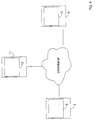
- FIG. 4 schematically shows an illustration of an embodiment with two system computers 8, 11, which are directly connected to a LAN.
- Both system computers 8, 11 each have a database 10, 12 for storing configuration, Maintenance and operating data from connected to the protocol converter 1 Facilities (not shown).
- the system computer 8, the a central database 10 is located in the control center, for example.
- the system computer 11 is a portable system computer in the form a notebook with which, for example, a customer service or maintenance technician can carry out diagnostics and maintenance of heating systems on site.
- the Maintenance technicians can use the heating system using the mobile system computer 11 configure and maintain.
- the current Configuration data from the database 12 to the central database 10 transmitted. In this way, the consistency of the databases 10, 12 can be ensured become.
- the connection and communication between the two system computers 8, 11 can be easily via the LAN or the Internet e.g. by the Internet Protocol IP.
- the plant operator leads, for example simple maintenance tasks themselves and leaves more complicated maintenance and Diagnostic tasks for the service personnel of the system manufacturer.
- the operator's control center is only partially staffed.
- remote monitoring is carried out by another control center.
- This can be a service center of the system manufacturer, for example, the central maintenance and remote monitoring of systems of many of its customers performs.
- By using the Internet to communicate between the Individual system computers 8, 11 can do such a distributed parameterization and Remote monitoring of facilities 2, 3, 4 enables in a cost-effective manner become.
- Passwords may be provided. Only registered and authorized users and systems can gain access to system computers 8, 11 and protocol converter 1. For example, an operator of a plant can contact the central customer service the system manufacturer's access rights to his protocol converter 1 and system computer Allow 8, 11. Furthermore, the data traffic between the individual Components of the device are encrypted.
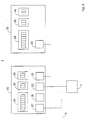
- FIG. 5 shows a schematic illustration of a possible exemplary embodiment a protocol converter according to the invention.
- the protocol converter 1 shown can advantageously consist of a basic module 20 and an expansion module 21 can be constructed.
- the basic module 20 has one Modem interface 22 according to the RS 232 specification with V.24 levels and with LED displays for selection and connection.
- the modem interface 22 will with a serial connection cable with the protocol converter modem 7 connected.
- the basic module 20 and the expansion module 21 each have an interface 23, for example an I2C bus interface.
- Basic module 20 and expansion module 21 can be easily connected to each other via the I 2 C bus. In this way, a flexible construction of a protocol converter 1 can be achieved. If required, additional expansion modules can be connected via the I 2 C bus, and an expanded protocol converter 1 with additional connection options can be created flexibly.
- Both basic module 20 and expansion module 21 can be digital or analog Have inputs and outputs. These can be used for a direct connection from further devices can be provided to the protocol converter 1.
- basic module 20 and expansion module 21 each have one digital input device 24 with eight digital inputs.
- the digital Inputs are suitable, for example, for recording operating states.
- base module 20 and expansion module 21 each have an analog one Input device 25 on.
- Each analog input device 25 has two analog ones Inputs for connecting measuring devices such as temperature sensors, for example on.
- the analog inputs are provided with analog / digital converters that simple acquisition of measured values and transmission of the digitized measured values enable to the system computer 8.
- the analog / digital converters have, for example an accuracy of 8 bits.
- Basic module 20 and expansion module 21 are each with an output device provided that have relay outputs for switching loads.
- the relay outputs can be used, for example, to switch devices on and off directly be provided.
- the basic module 20 can also have a LON interface 27 for connecting a Have LON bus system 5 to which the devices 2, 3, 4 are connected.
- the basic module 20 can have an Optolink interface 28.
- This Optical interface can be used for the trouble-free connection of a mobile system computer 8 be provided for maintenance and diagnosis on site.
- the protocol converter 1 have operating and display elements such as operating and fault displays. A corresponding power supply must also be provided.
- the embodiment of a protocol converter 1 shown in FIG. 5 enables one flexible structure.
- the inventive Protocol converter 1 consist solely of the basic module 20. Because of the engagement of one or more expansion modules 21, the protocol converter 1 can be expanded flexibly, and additional facilities can be easily added Connected to protocol converter 1 for remote maintenance, parameterization and control become.
- the protocol converter 1 is used by the system computer 8 a device connected to the bus system 5 treats and can itself be a receiver of messages and commands with which the directly connected Devices can be queried or influenced.
Abstract
Description
Claims (19)
- Vorrichtung, insbesondere zur Parametrierung und Fernüberwachung von Heizungsanlagen, mit
einem Systemrechner (8), der zur Übertragung von Daten nach einem ersten Datenübertragungsprotokoll geeignet ist,
mindestens einer Einrichtung (2, 3, 4), die zur Übertragung von Daten nach einem zweiten Datenübertragungsprotokoll geeignet ist,
einem Protokollkonverter (1), der mit dem Systemrechner (8) verbunden ist und der Daten des ersten Datenübertragungsprotokolls in Daten des zweiten Datenübertragungsprotokolls und umgekehrt konvertiert, und
einem Bussystem (5), an das die Einrichtungen (2, 3, 4) und der Protokollkonverter (1) anschließbar sind. - Vorrichtung nach Anspruch 1, wobei die an das Bussystem (5) anschließbaren Einrichtungen (2, 3, 4) Heizungs-, Klima- und/oder Kühlanlagen und/oder Meß- oder Steuereinrichtungen für den Betrieb von Heizungs-, Klimaund/oder Kühlanlagen sind.
- Vorrichtung nach Anspruch 1 oder 2, wobei das Bussystem (5) ein Haus- oder Feldbus ist und/oder das zweite Datenübertragungsprotokoll ein LON-Protokoll ist.
- Vorrichtung nach zumindest einem der Ansprüche 1 bis 3, wobei das erste Datenübertragungsprotokoll ein Protokoll auf der Basis des Internet Protocols IP, insbesondere das Simple Network Management Protocol SNMP, das Hypertext Transport Protocol HTTP, das Transport Control Protocol TCP oder das LonWorks Network Protocol, ist.
- Vorrichtung nach zumindest einem der Ansprüche 1 bis 4, wobei der Protokollkonverter (1) vorbestimmte Daten in vorgegebenen zeitlichen Abständen von den Einrichtungen (2, 3, 4) abfragt, speichert, an den Systemrechner (8) sendet und/oder zur Abfrage vom Systemrechner (8) bereit hält.
- Vorrichtung nach zumindest einem der Ansprüche 1 bis 5, wobei der Protokollkonverter (1) einen Speicher (6) für die Speicherung der von den Einrichtungen abgefragten Daten aufweist.
- Vorrichtung nach zumindest einem der Ansprüche 1 bis 6, wobei der Protokollkonverter (1) vom Systemrechner (8) empfangene Daten, die für eine bestimmte Einrichtung (2, 3, 4) bestimmt sind, über das Bussystem (5) an die entsprechende Einrichtung (2, 3, 4) sendet.
- Vorrichtung nach zumindest einem der Ansprüche 1 bis 7, wobei der Protokollkonverter (1) eine vorbestimmte Verbindung aktiviert, wenn von einer der Einrichtungen (2, 3, 4) eine Störungs- oder Wartungsmeldung vorliegt.
- Vorrichtung nach zumindest einem der Ansprüche 1 bis 8, wobei der Protokollkonverter (1) eine vorgegebene Nachricht, insbesondere ein Fax, eine Sprachnachricht, eine Email oder eine SMS-Nachricht, versendet, wenn von einer der Einrichtungen (2, 3, 4) eine Störungs- oder Wartungsmeldung vorliegt und die Verbindung zum Systemrechner (8) gestört ist.
- Vorrichtung nach zumindest einem der Ansprüche 1 bis 9, wobei die Verbindung zwischen dem Protokollkonverter (1) und dem Systemrechner (8) über eine analoge und/oder digitale Telefonverbindung erfolgt und ein analoges Modem, ein GSM-Modem oder ein ISDN-Modem (7, 9) aufweist.
- Vorrichtung nach Anspruch 10, wobei die Verbindung zwischen dem Protokollkonverter (1) und dem Systemrechner (8) über ein Rückrufverfahren aufgebaut wird.
- Vorrichtung nach zumindest einem der Ansprüche 1 bis 11, wobei der System rechner (8) in vorgegebenen zeitlichen Abständen eine Verbindung zu dem Protokollkonverter (1) aufbaut und vorbestimmte Daten abfragt, die der Protokollkonverter (1) zuvor von den Einrichtungen (2, 3, 4) abgefragt und zwischengespeichert hat.
- Vorrichtung nach zumindest einem der Ansprüche 1 bis 12, wobei der Systemrechner (8) eine Verbindung zu dem Protokollkonverter (1) aufbaut und/oder Daten für eine bestimmte Einrichtung (2, 3, 4) an den Protokollkonverter (1) sendet und/oder Daten von einer bestimmten Einrichtung (2, 3, 4) von dem Protokollkonverter (1) empfängt.
- Vorrichtung nach zumindest einem der Ansprüche 1 bis 13, wobei der Systemrechner (8) eine Datenbank (10) aufweist, die die Konfigurations-, Inbetriebnahme-, Wartungs- und/oder Betriebsdaten von Einrichtungen (2, 3, 4) und/oder dem Protokollkonverter (1), insbesondere Störungs- und Wartungsmeldungen, enthält.
- Vorrichtung nach Anspruch 14, wobei der Systemrechner einen Internetund/oder WAP-Server zum Zugriff auf die Datenbank (10) aufweist.
- Vorrichtung nach zumindest einem der Ansprüche 1 bis 15, wobei der Systemrechner (8) eine vorbestimmte Nachricht, insbesondere ein Fax, eine Sprachnachricht, eine Email oder eine SMS-Nachricht, versendet, wenn von einer der Einrichtungen (2, 3, 4) eine bestimmte Störungs- oder Wartungsmeldung vorliegt.
- Vorrichtung nach zumindest einem der Ansprüche 1 bis 16, wobei mehrere Systemrechner (8, 11) Verbindungen zu Protokollkonvertern (1) aufbauen und/oder Daten von den Protokollkonvertern (1) empfangen und/oder Daten an die Protokollkonverter (1) senden, wobei die Systemrechner (8, 11) über das Internet miteinander verbindbar sind.
- Vorrichtung nach Anspruch 17, wobei einer der Systemrechner (8) eine zentrale Datenbank (10) aufweist, an die die anderen Systemrechner (11) Datenänderungen melden und/oder mit der die Datenbanken (12) der anderen Systemrechner (11) abgeglichen werden.
- Verfahren, insbesondere zur Parametrierung und Fernüberwachung von Heizungsanlagen, mit den folgenden Schritten:Übertragung von Daten nach einem ersten Datenübertragungsprotokoll zwischen einem Systemrechner (8) und einem Protokollkonverter (1), Konvertierung der Daten des ersten Datenübertragungsprotokolls in Daten eines zweiten Datenübertragungsprotokolls und umgekehrt in dem Protokollkonverter (1), undÜbertragung von Daten nach dem zweiten Datenübertragungsprotokoll zwischen dem Protokollkonverter (1) und mindestens einer Einrichtung (2, 3, 4).
Applications Claiming Priority (2)
| Application Number | Priority Date | Filing Date | Title |
|---|---|---|---|
| DE10109196A DE10109196B4 (de) | 2001-02-26 | 2001-02-26 | Vorrichtung und Verfahren zur Fernüberwachung und Parametrierung von Einrichtungen, insbesondere von Heizungsanlagen |
| DE10109196 | 2001-02-26 |
Publications (2)
| Publication Number | Publication Date |
|---|---|
| EP1249982A2 true EP1249982A2 (de) | 2002-10-16 |
| EP1249982A3 EP1249982A3 (de) | 2006-01-04 |
Family
ID=7675520
Family Applications (1)
| Application Number | Title | Priority Date | Filing Date |
|---|---|---|---|
| EP02004209A Withdrawn EP1249982A3 (de) | 2001-02-26 | 2002-02-25 | Vorrichtung und Verfahren zur Datenkommunikation, insbesondere zur Parametrisierung und Fernüberwachung von Heizungsanlagen |
Country Status (4)
| Country | Link |
|---|---|
| US (1) | US7158525B2 (de) |
| EP (1) | EP1249982A3 (de) |
| CA (1) | CA2372825C (de) |
| DE (1) | DE10109196B4 (de) |
Families Citing this family (67)
| Publication number | Priority date | Publication date | Assignee | Title |
|---|---|---|---|---|
| US9210052B2 (en) * | 2002-06-17 | 2015-12-08 | Siemens Industry, Inc. | Streaming graphic method and arrangement data for building control systems |
| WO2004010645A1 (de) * | 2002-07-18 | 2004-01-29 | Vega Grieshaber Kg | Busstation mit integrierter busmonitorfunktion |
| DE10243781A1 (de) | 2002-09-20 | 2004-03-25 | Sick Ag | Elektronische Vorrichtung für ein Bussystem |
| DE10243783A1 (de) | 2002-09-20 | 2004-03-25 | Sick Ag | Elektronische Vorrichtung für ein Bussystem |
| DE10243782A1 (de) * | 2002-09-20 | 2004-03-25 | Sick Ag | Parametrier-/Diagnosesystem für Feldgeräte |
| US7480915B2 (en) * | 2002-10-03 | 2009-01-20 | Nokia Corporation | WV-IMS relay and interoperability methods |
| DE10307650A1 (de) | 2003-02-21 | 2004-09-02 | Endress + Hauser Gmbh + Co. Kg | Verfahren zum Übertragen von Daten über einen Feldbus der Prozessautomatisierungstechnik |
| DE20307101U1 (de) * | 2003-05-07 | 2003-07-10 | Siemens Ag | Automatisierungssystem mit vereinfachter Diagnose und Fehlerbehebung |
| DE10329871B4 (de) * | 2003-07-02 | 2017-12-28 | Volkswagen Ag | Verfahren und System zur telemetrischen Diagnose elektronischer Einrichtungen eines Fahrzeugs |
| WO2005041490A1 (de) * | 2003-09-25 | 2005-05-06 | Siemens Aktiengesellschaft | Nutzung von diensten innerhalb eines kommunikationsnetzes mit internetmechanismen und eines automatisierungssystems |
| US7949726B2 (en) * | 2004-03-12 | 2011-05-24 | Ocean And Coastal Environmental Sensing, Inc. | System and method for delivering information on demand |
| US20050228509A1 (en) * | 2004-04-07 | 2005-10-13 | Robert James | System, device, and method for adaptively providing a fieldbus link |
| KR100621571B1 (ko) * | 2004-06-25 | 2006-09-14 | 삼성전자주식회사 | 네트워크 중계장치 및 중계 방법 |
| KR100722271B1 (ko) | 2005-03-15 | 2007-05-28 | 엘지전자 주식회사 | 빌딩관리시스템 |
| DE102006006039A1 (de) * | 2006-02-09 | 2007-08-16 | Siemens Ag | Verfahren zum Überwachen und Steuern von für eine Elektroinstallation an einen Bus angeschlossenen Busteilnehmern |
| US7675935B2 (en) | 2006-05-31 | 2010-03-09 | Honeywell International Inc. | Apparatus and method for integrating wireless or other field devices in a process control system |
| US7965664B2 (en) * | 2006-05-31 | 2011-06-21 | Honeywell International Inc. | Apparatus and method for integrating wireless field devices with a wired protocol in a process control system |
| US7889747B2 (en) | 2006-05-31 | 2011-02-15 | Honeywell International Inc. | Apparatus, system, and method for integrating a wireless network with wired field devices in a process control system |
| US8266602B2 (en) * | 2006-05-31 | 2012-09-11 | Honeywell International Inc. | Apparatus and method for converting between device description languages in a process control system |
| US7876722B2 (en) * | 2006-05-31 | 2011-01-25 | Honeywell International Inc. | System and method for wireless communication between wired field devices and control system components |
| FR2902597B1 (fr) * | 2006-06-15 | 2008-09-12 | Elm Leblanc Sas Soc Par Action | Dispositif de communication a emission de rapport de panne pour chaudiere individuelle ou collective |
| US7735459B2 (en) * | 2006-06-23 | 2010-06-15 | Westcast, Inc. | Modular boiler control |
| US7953862B2 (en) * | 2007-01-16 | 2011-05-31 | Sony Ericsson Mobile Communications Ab | Methods for accessing a phone-based web server with a private IP address and related electronic devices and computer program products |
| KR100896996B1 (ko) * | 2007-02-02 | 2009-05-14 | 엘지전자 주식회사 | 멀티에어컨의 통합관리 시스템 및 방법 |
| DE102007010803B4 (de) | 2007-03-02 | 2009-06-04 | Viessmann Werke Gmbh & Co Kg | Vorrichtung und Verfahren zum Steuern und Überwachen von Haustechnikeinrichtungen |
| US7701970B2 (en) * | 2007-04-10 | 2010-04-20 | International Business Machines Corporation | Protocol negotiation for a group communication system |
| US8570922B2 (en) * | 2007-04-13 | 2013-10-29 | Hart Communication Foundation | Efficient addressing in wireless hart protocol |
| US8356431B2 (en) * | 2007-04-13 | 2013-01-22 | Hart Communication Foundation | Scheduling communication frames in a wireless network |
| US8406248B2 (en) | 2007-04-13 | 2013-03-26 | Hart Communication Foundation | Priority-based scheduling and routing in a wireless network |
| US8325627B2 (en) * | 2007-04-13 | 2012-12-04 | Hart Communication Foundation | Adaptive scheduling in a wireless network |
| US8230108B2 (en) * | 2007-04-13 | 2012-07-24 | Hart Communication Foundation | Routing packets on a network using directed graphs |
| US7627700B2 (en) * | 2007-06-05 | 2009-12-01 | Texas Instruments Incorporated | Expanded memory for communications controller |
| US7703202B2 (en) * | 2008-01-18 | 2010-04-27 | Inventec Corporation | Method for manufacturing a transmission line equalizer |
| US8213085B2 (en) * | 2008-01-18 | 2012-07-03 | Visera Technologies Company Limited | Image sensor device with high photosensitivity |
| US7899873B2 (en) * | 2008-05-20 | 2011-03-01 | At&T Intellectual Property I, L.P. | System and method of controlling a messaging system |
| JP2011527146A (ja) * | 2008-06-23 | 2011-10-20 | ハート コミュニケーション ファウンデーション | ワイヤレス通信ネットワークアナライザ |
| KR20100096808A (ko) * | 2009-02-25 | 2010-09-02 | 삼성전자주식회사 | 무선 통신 방법 및 장치 |
| US20100262403A1 (en) * | 2009-04-10 | 2010-10-14 | Bradford White Corporation | Systems and methods for monitoring water heaters or boilers |
| US8396203B2 (en) | 2009-10-20 | 2013-03-12 | At&T Intellectual Property I, L.P. | Automatic integrated escalation in a unified messaging system |
| US8517729B2 (en) * | 2010-03-04 | 2013-08-27 | The University of Western Ontario and Trudell Medical International | Oral mouthpiece and method for the use thereof |
| US8756412B2 (en) | 2010-04-16 | 2014-06-17 | Honeywell International Inc. | Gateway supporting transparent redundancy in process control systems and other systems and related method |
| EP2413047B2 (de) † | 2010-07-30 | 2021-11-17 | Grundfos Management A/S | Brauchwassererwärmungseinheit |
| US8498201B2 (en) | 2010-08-26 | 2013-07-30 | Honeywell International Inc. | Apparatus and method for improving the reliability of industrial wireless networks that experience outages in backbone connectivity |
| US8924498B2 (en) | 2010-11-09 | 2014-12-30 | Honeywell International Inc. | Method and system for process control network migration |
| US9239574B2 (en) | 2011-06-30 | 2016-01-19 | Honeywell International Inc. | Apparatus for automating field device operations by capturing device method execution steps for later use and related method |
| US20130085615A1 (en) * | 2011-09-30 | 2013-04-04 | Siemens Industry, Inc. | System and device for patient room environmental control and method of controlling environmental conditions in a patient room |
| US9441848B2 (en) * | 2012-05-09 | 2016-09-13 | Honeywell International Inc. | Airflow and water balancing |
| JP6053364B2 (ja) * | 2012-07-19 | 2016-12-27 | キヤノン株式会社 | 情報処理システム、サーバ装置、クライアント装置および制御方法 |
| US9762445B2 (en) | 2013-05-20 | 2017-09-12 | Trane International Inc. | Device and method for automatic switching of communication protocol of network devices based on user action |
| US9716637B1 (en) * | 2013-06-05 | 2017-07-25 | William Baker | Communication string network |
| US9191843B2 (en) | 2013-06-12 | 2015-11-17 | Honeywell International Inc. | Apparatus and method for measuring and reporting redundant wireless connectivity over time |
| US9110838B2 (en) | 2013-07-31 | 2015-08-18 | Honeywell International Inc. | Apparatus and method for synchronizing dynamic process data across redundant input/output modules |
| US9612587B2 (en) | 2014-02-11 | 2017-04-04 | Honeywell International Inc. | Mobile extension for industrial operator consoles |
| US9473876B2 (en) * | 2014-03-31 | 2016-10-18 | Blackberry Limited | Method and system for tunneling messages between two or more devices using different communication protocols |
| US9720404B2 (en) | 2014-05-05 | 2017-08-01 | Honeywell International Inc. | Gateway offering logical model mapped to independent underlying networks |
| US10042330B2 (en) | 2014-05-07 | 2018-08-07 | Honeywell International Inc. | Redundant process controllers for segregated supervisory and industrial control networks |
| US9609524B2 (en) | 2014-05-30 | 2017-03-28 | Honeywell International Inc. | Apparatus and method for planning and validating a wireless network |
| US10536526B2 (en) | 2014-06-25 | 2020-01-14 | Honeywell International Inc. | Apparatus and method for virtualizing a connection to a node in an industrial control and automation system |
| US9699022B2 (en) | 2014-08-01 | 2017-07-04 | Honeywell International Inc. | System and method for controller redundancy and controller network redundancy with ethernet/IP I/O |
| US10148485B2 (en) | 2014-09-03 | 2018-12-04 | Honeywell International Inc. | Apparatus and method for on-process migration of industrial control and automation system across disparate network types |
| US10162827B2 (en) | 2015-04-08 | 2018-12-25 | Honeywell International Inc. | Method and system for distributed control system (DCS) process data cloning and migration through secured file system |
| US10409270B2 (en) | 2015-04-09 | 2019-09-10 | Honeywell International Inc. | Methods for on-process migration from one type of process control device to different type of process control device |
| EP3385929B1 (de) * | 2015-12-29 | 2020-02-19 | Huawei Technologies Co., Ltd. | System, verfahren und vorrichtung zur informationsübertragung |
| US10296482B2 (en) | 2017-03-07 | 2019-05-21 | Honeywell International Inc. | System and method for flexible connection of redundant input-output modules or other devices |
| US10802512B2 (en) * | 2017-05-01 | 2020-10-13 | Johnson Controls Technology Company | HVAC device controller with integrated refrigeration controller interface |
| US10401816B2 (en) | 2017-07-20 | 2019-09-03 | Honeywell International Inc. | Legacy control functions in newgen controllers alongside newgen control functions |
| CN107491029A (zh) * | 2017-08-13 | 2017-12-19 | 中清源环保节能有限公司 | 一种用于集中供热的热控网通信传输平台 |
Citations (2)
| Publication number | Priority date | Publication date | Assignee | Title |
|---|---|---|---|---|
| WO2000046965A2 (de) | 1999-02-04 | 2000-08-10 | Siemens Aktiengesellschaft | Anordnung zum ineinanderübersetzen von protokolldateneinheiten inkompatible netze |
| WO2000056016A1 (de) | 1999-03-15 | 2000-09-21 | Siemens Ag Österreich | Vorrichtung zum schalten, steuern und überwachen von geräten |
Family Cites Families (7)
| Publication number | Priority date | Publication date | Assignee | Title |
|---|---|---|---|---|
| US5581478A (en) * | 1995-04-13 | 1996-12-03 | Cruse; Michael | Facility environmental control system |
| US6891838B1 (en) * | 1998-06-22 | 2005-05-10 | Statsignal Ipc, Llc | System and method for monitoring and controlling residential devices |
| DE19841476A1 (de) * | 1998-09-10 | 2000-03-30 | Electrowatt Tech Innovat Corp | Eingabesystem und Verfahren zur Eingabe von Prozeßparametern |
| US6763040B1 (en) * | 1999-04-29 | 2004-07-13 | Amx Corporation | Internet control system communication protocol and method |
| US6799202B1 (en) * | 1999-12-16 | 2004-09-28 | Hachiro Kawaii | Federated operating system for a server |
| US6606670B1 (en) * | 2000-08-16 | 2003-08-12 | Microchip Technology Incorporated | Circuit serial programming of default configuration |
| US6559783B1 (en) * | 2000-08-16 | 2003-05-06 | Microchip Technology Incorporated | Programmable auto-converting analog to digital conversion module |
-
2001
- 2001-02-26 DE DE10109196A patent/DE10109196B4/de not_active Revoked
-
2002
- 2002-02-22 CA CA002372825A patent/CA2372825C/en not_active Expired - Fee Related
- 2002-02-25 EP EP02004209A patent/EP1249982A3/de not_active Withdrawn
- 2002-02-26 US US10/085,817 patent/US7158525B2/en not_active Expired - Fee Related
Patent Citations (2)
| Publication number | Priority date | Publication date | Assignee | Title |
|---|---|---|---|---|
| WO2000046965A2 (de) | 1999-02-04 | 2000-08-10 | Siemens Aktiengesellschaft | Anordnung zum ineinanderübersetzen von protokolldateneinheiten inkompatible netze |
| WO2000056016A1 (de) | 1999-03-15 | 2000-09-21 | Siemens Ag Österreich | Vorrichtung zum schalten, steuern und überwachen von geräten |
Non-Patent Citations (1)
| Title |
|---|
| "Elektronik", 14 April 1998, WEKA FACHZEITSCHRIFTENVERLAG, article "Der Internet-Zugriff aufs LON. Weltweiter Zugriff auf die Sensorik und Aktorik von Automatisierungs-Projekten", pages: 60 |
Also Published As
| Publication number | Publication date |
|---|---|
| EP1249982A3 (de) | 2006-01-04 |
| CA2372825C (en) | 2007-04-17 |
| DE10109196B4 (de) | 2005-04-28 |
| DE10109196A1 (de) | 2002-09-12 |
| US7158525B2 (en) | 2007-01-02 |
| CA2372825A1 (en) | 2002-08-26 |
| US20020120671A1 (en) | 2002-08-29 |
Similar Documents
| Publication | Publication Date | Title |
|---|---|---|
| EP1249982A2 (de) | Vorrichtung und Verfahren zur Datenkommunikation, insbesondere zur Parametrisierung und Fernüberwachung von Heizungsanlagen | |
| EP1527554B1 (de) | Rechnernetzwerk mit diagnoserechnerknoten | |
| DE69933895T2 (de) | Funktionsblockvorrichtung zur Datenanzeige in einem Prozessteuersystem | |
| DE10222399B4 (de) | Steuerungsverfahren und System zur automatischen Vorbearbeitung von Gerätestörungen | |
| EP2118712B1 (de) | Scada-einheit | |
| DE102004055664A1 (de) | Zentrales Steuerungssystem für Klimaanlagen sowie Verfahren zum Betreiben desselben | |
| DE60113999T2 (de) | Wartungssystem für eine telekommunikationseinrichtung | |
| EP1783365A2 (de) | Verfahren zum Übertragen von Daten an eine Windenergieanlage und Windenergieanlage mit geigneter Auswerteeinrichtung | |
| DE602004001283T2 (de) | Apparat und Verfahren um separate Netzwerke zu verbinden | |
| DE102007010803B4 (de) | Vorrichtung und Verfahren zum Steuern und Überwachen von Haustechnikeinrichtungen | |
| WO2005104055A2 (de) | Verfahren und system zur fernüberwachung, fernsteuerung und/oder ferndiagnose eines gerätes | |
| WO2003094046A2 (de) | Verzeichnisdienst in einem automatisierungssystem | |
| WO2001086879A1 (de) | Verfahren zur steuerung und/oder überwachung von systemeinheiten, computernetzwerk zur durchführung des verfahrens und computerprogrammprodukt | |
| EP2054782B1 (de) | Datenaufnahmevorrichtung | |
| DE102004048394B4 (de) | Fernsteuerungssystem | |
| EP0786884B1 (de) | Verfahren zur Übertragung von Kennungen nach Anschluss eines elektrischen Gerätes an eine Busleitung | |
| WO2002103990A2 (de) | Zentrale administration eines callcenters | |
| WO2004055610A1 (de) | System und verfahren zur überwachung von technischen anlagen und objekten | |
| EP1222836B1 (de) | System zum austausch von daten | |
| DE60114350T2 (de) | Vorrichtung und Verfahren zur Abstandssteuerung von Haushaltsgeräten | |
| EP3537654A1 (de) | Verfahren und system zum ermitteln einer konfiguration einer schnittstelle | |
| DE60105400T2 (de) | Fernhilfe- und verwaltungs-system für haushaltsgeräten und insbesondere heizungskessel für heizzwecke | |
| EP1102167A1 (de) | Einrichtung und Betrieb einer Kommunikationsverbindung mit einem Steuergerät | |
| EP1195946A2 (de) | Verfahren zur Erbringung von Diensten in einem Netzwerk-Management-System mit einer offenen Systemarchitektur sowie Dienst-Objekt, Anforderungs-Objekt und Anforderungs-Manager hierzu | |
| DE10056469A1 (de) | Koppeleinrichtung und Koppelverfahren zur Kopplung von lokalen und globalen Netzwerken |
Legal Events
| Date | Code | Title | Description |
|---|---|---|---|
| PUAI | Public reference made under article 153(3) epc to a published international application that has entered the european phase |
Free format text: ORIGINAL CODE: 0009012 |
|
| AK | Designated contracting states |
Kind code of ref document: A2 Designated state(s): AT BE CH CY DE DK ES FI FR GB GR IE IT LI LU MC NL PT SE TR |
|
| AX | Request for extension of the european patent |
Free format text: AL;LT;LV;MK;RO;SI |
|
| RAP1 | Party data changed (applicant data changed or rights of an application transferred) |
Owner name: VIESSMANN WERKE GMBH & CO KG |
|
| PUAL | Search report despatched |
Free format text: ORIGINAL CODE: 0009013 |
|
| AK | Designated contracting states |
Kind code of ref document: A3 Designated state(s): AT BE CH CY DE DK ES FI FR GB GR IE IT LI LU MC NL PT SE TR |
|
| AX | Request for extension of the european patent |
Extension state: AL LT LV MK RO SI |
|
| 17P | Request for examination filed |
Effective date: 20060704 |
|
| AKX | Designation fees paid |
Designated state(s): AT BE CH CY DE DK ES FI FR GB GR IE IT LI LU MC NL PT SE TR |
|
| 17Q | First examination report despatched |
Effective date: 20100325 |
|
| GRAP | Despatch of communication of intention to grant a patent |
Free format text: ORIGINAL CODE: EPIDOSNIGR1 |
|
| STAA | Information on the status of an ep patent application or granted ep patent |
Free format text: STATUS: THE APPLICATION IS DEEMED TO BE WITHDRAWN |
|
| 18D | Application deemed to be withdrawn |
Effective date: 20120902 |