EP1249908A1 - Ensemble de montage de connecteur électrique - Google Patents
Ensemble de montage de connecteur électrique Download PDFInfo
- Publication number
- EP1249908A1 EP1249908A1 EP02290915A EP02290915A EP1249908A1 EP 1249908 A1 EP1249908 A1 EP 1249908A1 EP 02290915 A EP02290915 A EP 02290915A EP 02290915 A EP02290915 A EP 02290915A EP 1249908 A1 EP1249908 A1 EP 1249908A1
- Authority
- EP
- European Patent Office
- Prior art keywords
- support
- plate
- connector
- mounting assembly
- fixing
- Prior art date
- Legal status (The legal status is an assumption and is not a legal conclusion. Google has not performed a legal analysis and makes no representation as to the accuracy of the status listed.)
- Granted
Links
Images




Classifications
-
- H—ELECTRICITY
- H01—ELECTRIC ELEMENTS
- H01R—ELECTRICALLY-CONDUCTIVE CONNECTIONS; STRUCTURAL ASSOCIATIONS OF A PLURALITY OF MUTUALLY-INSULATED ELECTRICAL CONNECTING ELEMENTS; COUPLING DEVICES; CURRENT COLLECTORS
- H01R9/00—Structural associations of a plurality of mutually-insulated electrical connecting elements, e.g. terminal strips or terminal blocks; Terminals or binding posts mounted upon a base or in a case; Bases therefor
- H01R9/22—Bases, e.g. strip, block, panel
- H01R9/24—Terminal blocks
- H01R9/26—Clip-on terminal blocks for side-by-side rail- or strip-mounting
- H01R9/2608—Fastening means for mounting on support rail or strip
-
- Y—GENERAL TAGGING OF NEW TECHNOLOGICAL DEVELOPMENTS; GENERAL TAGGING OF CROSS-SECTIONAL TECHNOLOGIES SPANNING OVER SEVERAL SECTIONS OF THE IPC; TECHNICAL SUBJECTS COVERED BY FORMER USPC CROSS-REFERENCE ART COLLECTIONS [XRACs] AND DIGESTS
- Y10—TECHNICAL SUBJECTS COVERED BY FORMER USPC
- Y10T—TECHNICAL SUBJECTS COVERED BY FORMER US CLASSIFICATION
- Y10T403/00—Joints and connections
- Y10T403/59—Manually releaseable latch type
-
- Y—GENERAL TAGGING OF NEW TECHNOLOGICAL DEVELOPMENTS; GENERAL TAGGING OF CROSS-SECTIONAL TECHNOLOGIES SPANNING OVER SEVERAL SECTIONS OF THE IPC; TECHNICAL SUBJECTS COVERED BY FORMER USPC CROSS-REFERENCE ART COLLECTIONS [XRACs] AND DIGESTS
- Y10—TECHNICAL SUBJECTS COVERED BY FORMER USPC
- Y10T—TECHNICAL SUBJECTS COVERED BY FORMER US CLASSIFICATION
- Y10T403/00—Joints and connections
- Y10T403/60—Biased catch or latch
-
- Y—GENERAL TAGGING OF NEW TECHNOLOGICAL DEVELOPMENTS; GENERAL TAGGING OF CROSS-SECTIONAL TECHNOLOGIES SPANNING OVER SEVERAL SECTIONS OF THE IPC; TECHNICAL SUBJECTS COVERED BY FORMER USPC CROSS-REFERENCE ART COLLECTIONS [XRACs] AND DIGESTS
- Y10—TECHNICAL SUBJECTS COVERED BY FORMER USPC
- Y10T—TECHNICAL SUBJECTS COVERED BY FORMER US CLASSIFICATION
- Y10T403/00—Joints and connections
- Y10T403/60—Biased catch or latch
- Y10T403/606—Leaf spring
Definitions
- the present invention relates to a connector mounting assembly. electric comprising a longitudinal mounting plate provided with means for securing to at least one rail and hooking means arranged on the length of the plate, and at least one connector support comprising a front face, rear face, lower end and upper end, said support being provided with fixing means cooperating with the means hooking the plate to fix the support on the plate and means reception adapted to receive an appropriate connector accessible from the face before.
- This type of mounting assembly is very widely used in setting up work of distributors and sub-distributors housed in a cabinet.
- two vertical support rails are provided on which a plurality of plates are mounted horizontally.
- the mounting plates plus commonly referred to as strips, have a length practically standard 19 inch, hence the designation of 19 inch banners.
- the mounting plate or strip includes a vertical faceplate cut out of windows intended for receive electrical or optical connectors directly or indirectly, usually low voltage.
- the present invention is more particularly concerned with the case where mounting assembly includes connector brackets attached to the board mounting or strip.
- each connector support is fixed to the plate front at the reception windows.
- Connector supports can be attached directly to the edges of the window, or alternatively, the mounting plate or strip may include fixing means located on the rear face of the front plate provided with windows.
- Connector brackets can be attached to their windows either from the front face of the front plate or from its back side.
- the connector supports are reported on the front of the faceplate and therefore protrude horizontally from this front plate.
- connector supports include receiving means specific adapted to receive a particular type of electrical connectors or optics.
- the placement of connectors on such connector supports is carried out from the rear face of the connector support so as to present the connector insertion slot at the window respective formed by the mounting plate or strip.
- the mounting plate or strip is not yet attached to the vertical support rails.
- the supports of connectors can be mounted on the mounting plate or strip and the connection cables can be connected to different connectors.
- the connectors thus wired can be brought back in their connector support respective, and the mounting plate or strip thus equipped is finally attached to vertical support rails.
- the present invention aims to remedy the aforementioned drawbacks of the prior art by defining a mounting assembly to mounting plate and connector support in which the mounting of electrical or optical connectors is simplified, and does not require removal of the mounting plate for its vertical support rails.
- the present invention achieves this object by providing that the means hooks repeatedly extend substantially along a single line, and the support fixing means are located at one end of the support so that the support projects vertically from the plate, when the latter is subjected horizontally to at least one rail of vertical support.
- the front plate provided with reception windows constitutes a partition wall preventing access to connectors other than through windows
- the present invention there there is no vertical faceplate with reception windows, but at contrary to the linear plane hooking means from which the connector supports either up or down, but always vertically. Therefore, the connector supports are only maintained only by one of their ends, and preferably by their lower ends so that they protrude upward vertically from the stage.
- the mounting plate of the present invention no longer constitutes a headband in the sense of the prior art, since it no longer forms a front plate longitudinal vertical which gave the name of platinum band assembly of the prior art. In the absence of such a faceplate, it is no longer the mounting plate which constitutes the front face of the mounting assembly, but the front faces of the connector supports fixed to the mounting plate. Of this way, the mounting plate is no longer even visible once the connector supports are mounted.
- the mounting plate comprises a front side and a rear side, the front side of the connector support being located on the front side of the plate and the rear face of the support being directed towards the rear side of the plate, the connector fixing means cooperating with the means hooking the plate so that the connector support is removable from the plate by grasping the support on its front face from the side front of the plate and moving it away from the rear side of the plate.
- Each connector support can thus be removed individually from the plate with its respective connector attached without being hindered by the plate, as was the case previously in the prior art because of the front plate.
- the connector supports extend vertically upward from the mounting plate.
- the support reception means are located above the support means fixation.
- the support comprises mounting means intended to hold an accessory, said mounting means being located at level of the end opposite to that where the fixing means are located and are separated from the fixing means by the receiving means.
- the accessory mounting means are located at the top end free support directed away from the attachment means of the plate.
- the fixing means come in engagement with the attachment means during a translational movement horizontal when the plate is mounted on vertical rails.
- the supports of connectors can thus be added to or removed from the mounting plate from the front side of the stage and require no space or clearance higher or lower since the movement takes place horizontally and not vertically.
- This is indeed important, because in a distributor or a sub-distributor, there are several mounting plates arranged one above others without dividers. Therefore, it is more advantageous to be able to set up the supports with a horizontal displacement and not not vertical because it would then be necessary to remove the mounting plate located just above or below, which would cause even more work.
- the visible panel of the distributor or sub-distributor will be entirely made up of the front panels connector supports, not by the front plates of the strips of the prior art.
- the fixing means comprise latching means cooperating with the means for hooking the plate in end of translational movement.
- the fixing means form guiding elements in translation and snap-on profiles
- the attachment means form guide appendages on which the support guide elements are adapted to be engaged by sliding and retaining profiles cooperating with the latching profiles of the support.
- the means of latching include release means operable from the front face of the support.
- the unlocking means house a fixing nut for adapting a connector accessory.
- the release means are located at a base of fixing incorporating the fixing means.
- the plate comprises means for holding cables located behind the hooking means, the means of maintenance comprising cable housings intended to receive the cables of sliding way.
- the retention means cooperate with immobilizers capable of locking the cables in their housings respectively.
- the cables can thus be previously engaged in the means holding while the mounting plate is already attached to the support rails vertical.
- the supports can be mounted on the mounting plate by sliding the cables in the means holding. Once the support in place on the plate, simply immobilize the cables in their respective slots.
- the assembly assembly for electrical connectors essentially comprises two component parts, namely a mounting plate mounting 1 and one or more connector supports 2, 2 '.
- the connectors electrical or optical devices 3 and their accessories 5 are not part of assembly assembly, but are simply accessories. It is why we can say that the assembly set includes only two various components.
- This board 1 has a general configuration rather flat longitudinal, since it consists of a longitudinal base plate 10 intended to extend in a horizontal plane, once the platinum is mounted on vertical support rails.
- This base plate 10 includes two free longitudinal ends and two longitudinal edges, forming on the rear side 151 a vertical angle 15 and on the front side 111 a flap 11.
- the angle 15 on the rear side 151 forms a plurality of receiving housings 16, here twelve in number adapted to accommodate twenty-four cables of connection.
- the angle 15 forms elements of the subjection 17 adapted to cooperate with lateral consoles allowing the fixing of the plate on vertical support rails.
- the presence of the angle 15 makes it possible to strengthen the resistance of the plate to torsion.
- the flap 11 extends substantially parallel to the base plate 10 at a front edge area 101. It an intermediate space 110 is thus created between the flap 11 and the edge zone front 101.
- the flap 11 is connected to the front edge zone 101 by bridges 12 which form the front longitudinal end of the plate 1.
- bridges 12 which form the front longitudinal end of the plate 1.
- the flap 11 is made with slots 13 which extend parallel to each other from the front side 111 towards the rear side 151.
- the slots 13 are open on the front side 111 and are located between the bridges 12.
- the slots 13 are here twenty-three.
- the slots 13 thus define tongues 113 to which they are connected respectively the bridges 12.
- the slots 13 could even extend over the entire width of the flap 11 so that each tab 113 would then be individual and no longer connected together as shown in Figure 1. However, the connecting all the tabs together strengthens the holding of the tabs, and thus also the holding of the plate as a whole.
- the base plate 10 is further provided at its front edge area 101 with light 105 which forms openings through the front edge area 101. The function of these lights 105 will be given below.
- the configuration of the plate 10 at its front side 111 is at say at the level of its flap 11 and of its front edge zone 101 connected by the bridges 12, constitutes attachment means intended to cooperate with the supports of connectors for fixing these on the mounting plate.
- the arrangement of tabs 113 and bridges 12 forms a plurality of sites hooks which repeatedly extend substantially along a single line defined by the front edge of the plate 10 on the front side 111.
- the attachment means form twenty-four hanging sites arranged side by side on a single line. Indeed, all the tabs 113 are located in the same horizontal plane, while in the prior art, the front fixing face extended in a vertical plane.
- Each hanging site includes a tongue and two lights.
- the mounting assembly also includes a, and preferably several connector supports designated by the reference numeral 2 or 2 '.
- the connector 2 of the Figures 2 and 3 indeed, the connector 2 'of Figure 5 differs only in its width and the type of connectors it is intended to accommodate.
- the connector support 2 includes a base 20 located at its lower end 201 from which extends the rest of the support.
- the support defines a front face 211, a rear face 212, a lower end 201 and an upper end 221.
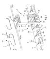
- the base 20 defines fixing means intended to cooperate with the attachment means formed by the mounting plate 1. More precisely, the base 20 forms a fixing housing 102 open towards the rear face and closed on the front face, in which a tongue 113 of the plate 10 can be sliding in a horizontal translational movement. In reality, this is the connector support that we just brought to the plate 1 in pushing the housing of the base 20 on a tongue 113. It is therefore understood easily that the connector supports are fitted on the circuit board mounting 1 from the front side 111 of the plate by moving the support towards the front side 111 of the plate in the direction of its rear side 151. The displacement is translative in a horizontal plane, i.e. in the same plane as the base plate 10 of the plate 1.
- the housing of the base 20 which serves as a guide element for the support on the tongue of the plate, extends well heard in a horizontal plane, i.e. in the same plane as the tabs 113 to be able to insert them into the housing.
- the simple commitment by force or by friction of the tongue 113 in the fixing housing 102 is sufficient to fix the support 2 on the plate 1.
- snap lugs 205 formed by the base 20 and intended to come in retaining socket in the lights 105 formed in the front edge area 101 of the base plate 10.
- the snap lugs 205 come to relax elastically in the lights 105, thus preventing the sliding removal of the plate support. And to allow the release, i.e. the removal of the pins 205 from the interior of the lights 105, provision is made for unlocking means 206 accessible from the face front 211 of the connector support. Thus, it is possible to remove the support from the plate from its front face 211 without having to access its rear face 212.
- the base 20 forms an upper plate 203 which comes place above the tongue 113 of the plate 1 which serves as an appendage of guide for the support, as can be seen in FIG. 4.
- This plate 203 forms with its lower surface the upper part of the fixing housing 202.
- the housing 202 is therefore formed just below the plate 203.
- the base 20 forms two lateral bars 204 which come lodge in the intermediate space 110 formed between the flap 11 and the edge area front 101 of 1 plate 1. The engagement of the side bars 204 in this space 110 with very little play allows to further improve the stability of the fixing the connector support 2 on the plate 1.
- the side bars 204 point backwards from front panel 211 where they connect to a actuating stirrup 209 on which the latching lugs 205 are formed.
- This actuating bracket 209 extends inside the lateral bars 204 with the core of the stirrup forming a release actuator 206 accessible from the front face 211 of the connector support.
- the binding of the stirrup 209 with the lateral bars 204 is elastic so that the moving the caliper up allows you to disengage the pins snap-fit 205 from inside the lights 105. Similarly, the elasticity of the stirrup allows the engagement of the pins 205 in the slots 105.
- the stirrup 209 when when the support is placed on the plate, the stirrup 209 is elastically deformed upward to allow the snap pins 205 to move on the front edge zone 101 up to the lights 105.
- the core of the stirrup forming the actuating member is advantageously provided with a receiving housing 107 for a nut used for fixing a mounting accessory connector, such as a duplicator.
- the base 20 also forms buttresses 208 which can serve as abutment elements against the front edge of the plate on either side of a bridge 12. These buttresses 208 extend as far as below the base plate 10 of the plate 1.
- the support 1 forms receiving means 21 intended to receive an optical or electrical connector 3 of the type suitable for connector support.
- These reception means comprise a window 213 to through which the connector housing 31 of the connector 3 is accessible from the front face 211 of the connector support.
- the means of reception are also defined by the plate 203 which serves as a support surface for the connector 3.
- the receiving means 21 may include other bars or hooking or snap-fastening elements 215 making it possible to maintain the connector on tray 203 with its receiving housing 31 inserted in the window 213. It can be said that the reception means 21 are located above the base 20 for fixing the support on the plate. The means of fixing therefore occupy the lower part of the support while the means of reception 21 are located above these fixing means.
- the support 2 also forms mounting means 22 for mounting a connector accessory, such an optical fiber coiling cassette, which is frequently associated with a optical connector.
- These mounting means define a housing for mounting 22 formed by bars or mounting elements 215 and a plate upper 221 forming the upper end of the connector.
- the support can form a panel 223 which can advantageously be used for receipt of an indication banner to identify the connectors and their attributions.
- the mounting means 22 are located on the upper floor of the connector support 2. Consequently, it can be said that the base 20 with its fixing means to the plate are located on the lower stage of the support, the receiving means 21 in the intermediate position and the mounting means 22 to the upper floor. There is thus a connector support arranged vertically, and no longer horizontally as was the case in art prior.
- Figure 4 shows a connector support as described above mounted on a mounting plate as described above. You can see that the connector support projects upwards from plate 1: Indeed, only the base is fixed to the plate, with the plate 203 located just above of the tongue 113 and the release member 206 accessible on the front face. From this tray 203, the support 2 is completely independent of the plate 1 and therefore extends freely upwards to define the means of reception 21 and the mounting means 22.
- the support 2 ′ has a pitch equal to the double that of connector 2.
- the pitch of the mounting assembly is defined by the gap between the slots 13 which corresponds approximately to the width of the tabs 113.
- the connector support 2 is provided with a connector 3 engaged in the receiving means 21 so as to present the plug-in housing 31 at the window 213.
- the connector 3 is connected to a connection cable 4 which passes through a housing 16 formed by the angle 15 of the plate 10.
- the cable 4 is blocked in the housing 16 by an immobilizing member 21 which blocks the cable 4 in position in the housing 16.
- This immobilizing member 161 can for example be made of a flexible material which exerts pressure and also force friction on the cable 4 which allows to immobilize it in the housing 16.
- an optical fiber coiling cassette 5 is placed in the mounting means 22.
- This coiling cassette is an accessory commonly used in combination with an optical connector which can example be received in the connector support 2 '. We can see that the cassette coiling 5 is inserted in the mounting means 22 but also takes presses on the angle 15, which provides very good stability for accessory 5.
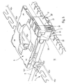
- FIGS. 7 and 8 it can be seen how the base 20 of the connector supports 2 and 2 'cooperate with the plate 1 for fixing them.
- the side bars 204 are engaged between the flap 11 and the front edge region 101 of the base plate 10 with the release 206 located just in front of bridge 12 and platform 203 just extends above the flap 11.
- FIG. 8 one can clearly see a tongue 213 engaged in the housing 202 of the support 2 and two tabs 213 engaged in the fixing housing 202 'of the support 2'.
Landscapes
- Connector Housings Or Holding Contact Members (AREA)
- Light Guides In General And Applications Therefor (AREA)
Abstract
Description
- la figure 1 est une vue en perspective d'une platine de montage selon l'invention,
- les figures 2 et 3 sont des vues en perspective avec des angles différents d'un support de connecteurs selon l'invention,
- la figure 4 est une vue en perspective du support de connecteurs des figures 2 et 3 monté sur la platine de montage de la figure 1,
- la figure 5 est une vue en perspective d'un ensemble de montage de l'invention équipé de connecteurs et d'un accessoire de connecteurs,
- la figure 6 est une vue en perspective de dessous des supports de connecteurs de la figure 5 montés sur la platine de montage, et
- les figures 7 et 8 sont des vues en coupe transversale verticale selon deux axes perpendiculaires à travers l'ensemble de montage de la figure 6.
Claims (14)
- Ensemble de montage de connecteur électrique comprenant :caractérisé en ce que les moyens d'accrochage (113 ; 105) s'étendent de manière répétée sensiblement le long d'une seule ligne, et les moyens de fixation (202, 205) du support sont situés au niveau d'une extrémité du support de sorte que le support fait saillie verticalement à partir de la platine, lorsque cette dernière est assujettie à un rail de support vertical.une platine de montage longitudinale (1) pourvue de moyens d'assujettissement (17) à au moins un rail et de moyens d'accrochage (113) disposés sur la longueur de la platine, etau moins un support de connecteur (2) comprenant une face avant (211), une face arrière (212), une extrémité inférieure (201) et une extrémité supérieure (221), ledit support étant pourvu de moyens de fixation (202, 205) coopérant avec les moyens d'accrochage (113, 105) de la platine pour fixer le support sur la platine et de moyens de réception (21) adaptés à recevoir un connecteur approprié (3) accessible depuis la face avant,
- Ensemble de montage selon la revendication 1, dans lequel les moyens de fixation (202, 205) du support sont situés au niveau de l'extrémité inférieure (201) du support de sorte qu'il fait saillie vers le haut à partir de la platine.
- Ensemble de montage selon la revendication 2, dans lequel les moyens de réception (21) du support sont situés au-dessus des moyens de fixation (202, 205).
- Ensemble de montage selon la revendication 3, dans lequel le support comprend des moyens de montage (22) destinés à maintenir un accessoire (5), lesdits moyens de montage (22) étant situés au niveau de l'extrémité opposée (221) à celle où sont situés les moyens de fixation et sont séparés des moyens de fixation (202, 205) par les moyens de réception (21).
- Ensemble de montage selon la revendication 4, dans lequel les moyens de montage d'accessoire (22) sont situés au niveau de l'extrémité supérieure libre (221) du support dirigée en éloignement des moyens d'accrochage (113, 105) de la platine.
- Ensemble de montage selon l'une quelconque des revendications précédentes, dans lequel les moyens de fixation (202, 205) viennent en prise avec les moyens d'accrochage (113, 105) lors d'un déplacement translatif horizontal lorsque la platine est montée sur des rails verticaux.
- Ensemble de montage selon la revendication 6, dans lequel les moyens de fixation comprennent des moyens d'encliquetage (205) coopérant avec les moyens d'accrochage (105) de la platine en fin de déplacement translatif.
- Ensemble de montage selon la revendication 6 ou 7, dans lequel les moyens de fixation forment des éléments de guidage (202) en translation et des profils d'encliquetage (205), et les moyens d'accrochage forment des appendices de guidage (113) sur lesquels les éléments de guidage du support sont adaptés à être engagés par coulissement et des profils de retenue (105) coopérant avec les profils d'encliquetage du support.
- Ensemble de montage selon la revendication 7 ou 8, dans lequel les moyens d'encliquetage (205) comprennent des moyens de désencliquetage (206) actionnables depuis la face avant (211) du support.
- Ensemble de montage selon la revendication 9, dans lequel les moyens de désencliquetage (206) abritent un écrou de fixation pour l'adaptation d'un accessoire de connecteur.
- Ensemble de montage selon la revendication 9 ou 10, dans lequel les moyens de désencliquetage (206) sont situés au niveau d'une embase de fixation (20) intégrant les moyens de fixation.
- Ensemble de montage selon l'une quelconque des revendications précédentes, dans lequel la platine comprend des moyens de maintien de câbles situés en arrière des moyens d'accrochage (113, 105), les moyens de maintien comprenant des logements de câbles (16) destinés à recevoir les câbles de manière coulissante.
- Ensemble de montage selon la revendication 12, dans lequel les moyens de rétention (16) coopèrent avec des organes d'immobilisation (161) aptes à bloquer les câbles dans leurs logements respectifs.
- Ensemble de montage selon l'une quelconque des revendications précédentes, dans lequel la platine de montage comprend un côté avant (111) et un côté arrière (151), la face avant (211) du support de connecteur étant situé du côté avant (111) de la platine et la face arrière (212) du support étant dirigée vers le côté arrière (151) de la platine, les moyens de fixation (202, 205) du connecteur coopérant avec les moyens d'accrochage (113, 105) de la platine de manière à ce que le support de connecteur est retirable de la platine en saisissant le support par sa face avant à partir du côté avant de la platine et en le déplaçant en éloignement du côté arrière de la platine.
Applications Claiming Priority (2)
| Application Number | Priority Date | Filing Date | Title |
|---|---|---|---|
| FR0105086A FR2823602B1 (fr) | 2001-04-12 | 2001-04-12 | Ensemble de montage de connecteur electrique |
| FR0105086 | 2001-04-12 |
Publications (2)
| Publication Number | Publication Date |
|---|---|
| EP1249908A1 true EP1249908A1 (fr) | 2002-10-16 |
| EP1249908B1 EP1249908B1 (fr) | 2011-11-16 |
Family
ID=8862322
Family Applications (1)
| Application Number | Title | Priority Date | Filing Date |
|---|---|---|---|
| EP02290915A Expired - Lifetime EP1249908B1 (fr) | 2001-04-12 | 2002-04-12 | Ensemble de montage de connecteur électrique |
Country Status (4)
| Country | Link |
|---|---|
| US (1) | US6848854B2 (fr) |
| EP (1) | EP1249908B1 (fr) |
| ES (1) | ES2375949T3 (fr) |
| FR (1) | FR2823602B1 (fr) |
Families Citing this family (13)
| Publication number | Priority date | Publication date | Assignee | Title |
|---|---|---|---|---|
| DE102004060583B4 (de) * | 2004-12-16 | 2009-03-05 | Siemens Ag | Stromschiene für ein Flachmodul |
| WO2007089682A2 (fr) * | 2006-01-31 | 2007-08-09 | Commscope Inc. Of North Carolina | Ensembles panneaux de communication et leurs procedes de fixation |
| US7815152B2 (en) * | 2007-02-21 | 2010-10-19 | Adc Telecommunications, Inc. | Coupler for cable trough |
| JP5451274B2 (ja) * | 2009-09-11 | 2014-03-26 | 矢崎総業株式会社 | ワイヤハーネス配索装置 |
| CN102548263A (zh) * | 2010-12-15 | 2012-07-04 | 鸿富锦精密工业(深圳)有限公司 | 电子装置壳体 |
| US9381869B2 (en) | 2010-12-17 | 2016-07-05 | Southern Audio Services, Inc. | Accessory mounting assembly |
| US9381870B2 (en) | 2010-12-17 | 2016-07-05 | Southern Audio Services, Inc. | Accessory mounting assembly |
| US9050936B2 (en) | 2010-12-17 | 2015-06-09 | Southern Audio Services, Inc. | Accessory mounting assembly |
| JP5644644B2 (ja) * | 2011-04-11 | 2014-12-24 | 株式会社オートネットワーク技術研究所 | 配線モジュール |
| WO2014176029A1 (fr) * | 2013-04-22 | 2014-10-30 | Southern Audio Services, Inc. | Ensemble de montage d'accessoire |
| USD772169S1 (en) * | 2015-07-17 | 2016-11-22 | Conrad Louis Chompff | Cable/wire organizer |
| DE102016201425B4 (de) * | 2016-01-29 | 2026-02-05 | Eaton Intelligent Power Limited | Befestigungsvorrichtung |
| JP7588031B2 (ja) * | 2021-05-19 | 2024-11-21 | 日立Astemo株式会社 | 電子制御装置 |
Citations (2)
| Publication number | Priority date | Publication date | Assignee | Title |
|---|---|---|---|---|
| FR2688354A3 (en) * | 1992-03-09 | 1993-09-10 | Mod Tap W Corp | Connectors for screened cables |
| EP0762586A1 (fr) * | 1995-08-29 | 1997-03-12 | Legrand | Coffret, notamment pour appareils électriques |
Family Cites Families (3)
| Publication number | Priority date | Publication date | Assignee | Title |
|---|---|---|---|---|
| US6003804A (en) * | 1994-10-18 | 1999-12-21 | Vara; James E. | Enhanced storage system for electrical appliances, powercords and adapters |
| US6170784B1 (en) * | 1998-06-18 | 2001-01-09 | Polygon Wire Management, Inc. | Cable management device |
| US6403885B1 (en) * | 1999-12-02 | 2002-06-11 | Avaya Technology Corp. | Integral cable retention device |
-
2001
- 2001-04-12 FR FR0105086A patent/FR2823602B1/fr not_active Expired - Fee Related
-
2002
- 2002-04-11 US US10/119,831 patent/US6848854B2/en not_active Expired - Fee Related
- 2002-04-12 ES ES02290915T patent/ES2375949T3/es not_active Expired - Lifetime
- 2002-04-12 EP EP02290915A patent/EP1249908B1/fr not_active Expired - Lifetime
Patent Citations (2)
| Publication number | Priority date | Publication date | Assignee | Title |
|---|---|---|---|---|
| FR2688354A3 (en) * | 1992-03-09 | 1993-09-10 | Mod Tap W Corp | Connectors for screened cables |
| EP0762586A1 (fr) * | 1995-08-29 | 1997-03-12 | Legrand | Coffret, notamment pour appareils électriques |
Also Published As
| Publication number | Publication date |
|---|---|
| US20020171339A1 (en) | 2002-11-21 |
| US6848854B2 (en) | 2005-02-01 |
| ES2375949T3 (es) | 2012-03-07 |
| FR2823602A1 (fr) | 2002-10-18 |
| FR2823602B1 (fr) | 2003-10-17 |
| EP1249908B1 (fr) | 2011-11-16 |
Similar Documents
| Publication | Publication Date | Title |
|---|---|---|
| EP1249908B1 (fr) | Ensemble de montage de connecteur électrique | |
| EP1127394B1 (fr) | Dispositif de fixation d'un fil sur un element porteur muni d'au moins une ouverture et ensemble porteur pour chemin de cables comportant au moins un tel dispositif | |
| EP1192693A1 (fr) | Accessoire de fixation pour chemin de cables en fils, et chemin de cables en fils equipe au moins d'un tel accessoire | |
| FR2531576A1 (fr) | Bati de raccordement et d'interface opto-electronique | |
| BE1005298A5 (fr) | Systeme adaptatif de montage de cartes. | |
| US20030103730A1 (en) | Optical splitter module | |
| EP0542594B1 (fr) | Ensemble électronique modulaire | |
| FR2499613A1 (fr) | Grille pour plafond suspendu et procede de fabrication | |
| FR2558678A1 (fr) | Coffret pour equipement electronique | |
| EP0838700A1 (fr) | Dispositif d'épissurage mécanique multivoies pour câbles à fibres optiques | |
| EP0237410A1 (fr) | Coffret de logement d'appareillages électriques | |
| FR2953655A1 (fr) | Dispositif de fixation destine a la fixation d'un accessoire sur un chemin de cables en fils | |
| FR2738445A1 (fr) | Accessoire de support pour l'assujettissement d'un barreau a un autre element de chassis, notamment pour le support d'appareils electriques | |
| JP3304461B2 (ja) | 照明器具のカバー係止装置 | |
| EP1542329A1 (fr) | Console de montage pour chemins de câbles | |
| EP0675230B1 (fr) | Dispositif de verrouillage d'une grille sur un châssis ou analogue | |
| EP0243227A1 (fr) | Dispositif de fixation de panneaux de revêtement de murs et de plafonds | |
| JP2000039525A (ja) | スプライス棚 | |
| EP1191657B1 (fr) | Dispositif de fixation d'une goulotte sur un support décalé par rapport à un mur | |
| EP0848470B1 (fr) | Goulotte de distribution électrique et utilisation d'une telle goulotte | |
| FR2818818A1 (fr) | Console pour le support d'un chemin de cable ou analogues forme d'une succession de goulottes en tole | |
| FR2719736A1 (fr) | Dispositif de montage pour plastron à rapporter sur deux montants, notamment pour coffret ou autre armoire électrique, et plastron et coffret correspondants. | |
| FR2804547A1 (fr) | Support d'appareillages electriques et chemin de cable comportant un tel support | |
| FR2773855A1 (fr) | Dispositif de fixation d'elements a fixer | |
| FR3056373A1 (fr) | Equipement pour maintenir un composant a l'interieur d'un boitier d'ordinateur |
Legal Events
| Date | Code | Title | Description |
|---|---|---|---|
| PUAI | Public reference made under article 153(3) epc to a published international application that has entered the european phase |
Free format text: ORIGINAL CODE: 0009012 |
|
| AK | Designated contracting states |
Kind code of ref document: A1 Designated state(s): AT BE CH CY DE DK ES FI FR GB GR IE IT LI LU MC NL PT SE TR |
|
| AX | Request for extension of the european patent |
Free format text: AL;LT;LV;MK;RO;SI |
|
| 17P | Request for examination filed |
Effective date: 20030414 |
|
| AKX | Designation fees paid |
Designated state(s): AT BE CH CY DE LI |
|
| RBV | Designated contracting states (corrected) |
Designated state(s): BE ES FR GB IT |
|
| RIN1 | Information on inventor provided before grant (corrected) |
Inventor name: MASSE,DOMINIQUE |
|
| REG | Reference to a national code |
Ref country code: DE Ref legal event code: 8566 |
|
| GRAP | Despatch of communication of intention to grant a patent |
Free format text: ORIGINAL CODE: EPIDOSNIGR1 |
|
| GRAS | Grant fee paid |
Free format text: ORIGINAL CODE: EPIDOSNIGR3 |
|
| GRAA | (expected) grant |
Free format text: ORIGINAL CODE: 0009210 |
|
| AK | Designated contracting states |
Kind code of ref document: B1 Designated state(s): BE ES FR GB IT |
|
| REG | Reference to a national code |
Ref country code: GB Ref legal event code: FG4D Free format text: NOT ENGLISH |
|
| RAP2 | Party data changed (patent owner data changed or rights of a patent transferred) |
Owner name: INFRAPLUS |
|
| REG | Reference to a national code |
Ref country code: ES Ref legal event code: FG2A Ref document number: 2375949 Country of ref document: ES Kind code of ref document: T3 Effective date: 20120307 |
|
| REG | Reference to a national code |
Ref country code: GB Ref legal event code: 732E Free format text: REGISTERED BETWEEN 20120322 AND 20120328 |
|
| PLBE | No opposition filed within time limit |
Free format text: ORIGINAL CODE: 0009261 |
|
| STAA | Information on the status of an ep patent application or granted ep patent |
Free format text: STATUS: NO OPPOSITION FILED WITHIN TIME LIMIT |
|
| 26N | No opposition filed |
Effective date: 20120817 |
|
| REG | Reference to a national code |
Ref country code: FR Ref legal event code: PLFP Year of fee payment: 15 |
|
| REG | Reference to a national code |
Ref country code: FR Ref legal event code: PLFP Year of fee payment: 16 |
|
| REG | Reference to a national code |
Ref country code: FR Ref legal event code: PLFP Year of fee payment: 17 |
|
| PGFP | Annual fee paid to national office [announced via postgrant information from national office to epo] |
Ref country code: FR Payment date: 20200309 Year of fee payment: 19 |
|
| PGFP | Annual fee paid to national office [announced via postgrant information from national office to epo] |
Ref country code: ES Payment date: 20200518 Year of fee payment: 19 |
|
| PGFP | Annual fee paid to national office [announced via postgrant information from national office to epo] |
Ref country code: BE Payment date: 20200415 Year of fee payment: 19 Ref country code: GB Payment date: 20200427 Year of fee payment: 19 Ref country code: IT Payment date: 20200410 Year of fee payment: 19 |
|
| GBPC | Gb: european patent ceased through non-payment of renewal fee |
Effective date: 20210412 |
|
| REG | Reference to a national code |
Ref country code: BE Ref legal event code: MM Effective date: 20210430 |
|
| PG25 | Lapsed in a contracting state [announced via postgrant information from national office to epo] |
Ref country code: GB Free format text: LAPSE BECAUSE OF NON-PAYMENT OF DUE FEES Effective date: 20210412 Ref country code: FR Free format text: LAPSE BECAUSE OF NON-PAYMENT OF DUE FEES Effective date: 20210430 |
|
| REG | Reference to a national code |
Ref country code: ES Ref legal event code: FD2A Effective date: 20220701 |
|
| PG25 | Lapsed in a contracting state [announced via postgrant information from national office to epo] |
Ref country code: ES Free format text: LAPSE BECAUSE OF NON-PAYMENT OF DUE FEES Effective date: 20210413 Ref country code: BE Free format text: LAPSE BECAUSE OF NON-PAYMENT OF DUE FEES Effective date: 20210430 |
|
| PG25 | Lapsed in a contracting state [announced via postgrant information from national office to epo] |
Ref country code: IT Free format text: LAPSE BECAUSE OF NON-PAYMENT OF DUE FEES Effective date: 20200412 |
|
| PG25 | Lapsed in a contracting state [announced via postgrant information from national office to epo] |
Ref country code: IT Free format text: LAPSE BECAUSE OF NON-PAYMENT OF DUE FEES Effective date: 20210412 |