EP1248324B1 - Terminal for electrical connector and terminal blank with a carrier - Google Patents
Terminal for electrical connector and terminal blank with a carrier Download PDFInfo
- Publication number
- EP1248324B1 EP1248324B1 EP02007505A EP02007505A EP1248324B1 EP 1248324 B1 EP1248324 B1 EP 1248324B1 EP 02007505 A EP02007505 A EP 02007505A EP 02007505 A EP02007505 A EP 02007505A EP 1248324 B1 EP1248324 B1 EP 1248324B1
- Authority
- EP
- European Patent Office
- Prior art keywords
- terminal
- carrier
- contact
- contact blades
- contact blade
- Prior art date
- Legal status (The legal status is an assumption and is not a legal conclusion. Google has not performed a legal analysis and makes no representation as to the accuracy of the status listed.)
- Expired - Fee Related
Links
Images

Classifications
-
- H—ELECTRICITY
- H01—ELECTRIC ELEMENTS
- H01R—ELECTRICALLY-CONDUCTIVE CONNECTIONS; STRUCTURAL ASSOCIATIONS OF A PLURALITY OF MUTUALLY-INSULATED ELECTRICAL CONNECTING ELEMENTS; COUPLING DEVICES; CURRENT COLLECTORS
- H01R9/00—Structural associations of a plurality of mutually-insulated electrical connecting elements, e.g. terminal strips or terminal blocks; Terminals or binding posts mounted upon a base or in a case; Bases therefor
- H01R9/22—Bases, e.g. strip, block, panel
-
- H—ELECTRICITY
- H01—ELECTRIC ELEMENTS
- H01R—ELECTRICALLY-CONDUCTIVE CONNECTIONS; STRUCTURAL ASSOCIATIONS OF A PLURALITY OF MUTUALLY-INSULATED ELECTRICAL CONNECTING ELEMENTS; COUPLING DEVICES; CURRENT COLLECTORS
- H01R13/00—Details of coupling devices of the kinds covered by groups H01R12/70 or H01R24/00 - H01R33/00
- H01R13/02—Contact members
- H01R13/10—Sockets for co-operation with pins or blades
- H01R13/11—Resilient sockets
- H01R13/112—Resilient sockets forked sockets having two legs
-
- H—ELECTRICITY
- H01—ELECTRIC ELEMENTS
- H01R—ELECTRICALLY-CONDUCTIVE CONNECTIONS; STRUCTURAL ASSOCIATIONS OF A PLURALITY OF MUTUALLY-INSULATED ELECTRICAL CONNECTING ELEMENTS; COUPLING DEVICES; CURRENT COLLECTORS
- H01R13/00—Details of coupling devices of the kinds covered by groups H01R12/70 or H01R24/00 - H01R33/00
- H01R13/02—Contact members
- H01R13/04—Pins or blades for co-operation with sockets
-
- H—ELECTRICITY
- H01—ELECTRIC ELEMENTS
- H01R—ELECTRICALLY-CONDUCTIVE CONNECTIONS; STRUCTURAL ASSOCIATIONS OF A PLURALITY OF MUTUALLY-INSULATED ELECTRICAL CONNECTING ELEMENTS; COUPLING DEVICES; CURRENT COLLECTORS
- H01R13/00—Details of coupling devices of the kinds covered by groups H01R12/70 or H01R24/00 - H01R33/00
- H01R13/02—Contact members
- H01R13/22—Contacts for co-operating by abutting
- H01R13/24—Contacts for co-operating by abutting resilient; resiliently-mounted
- H01R13/2442—Contacts for co-operating by abutting resilient; resiliently-mounted with a single cantilevered beam
-
- H—ELECTRICITY
- H01—ELECTRIC ELEMENTS
- H01R—ELECTRICALLY-CONDUCTIVE CONNECTIONS; STRUCTURAL ASSOCIATIONS OF A PLURALITY OF MUTUALLY-INSULATED ELECTRICAL CONNECTING ELEMENTS; COUPLING DEVICES; CURRENT COLLECTORS
- H01R43/00—Apparatus or processes specially adapted for manufacturing, assembling, maintaining, or repairing of line connectors or current collectors or for joining electric conductors
- H01R43/16—Apparatus or processes specially adapted for manufacturing, assembling, maintaining, or repairing of line connectors or current collectors or for joining electric conductors for manufacturing contact members, e.g. by punching and by bending
Definitions
- the present invention relates to terminals for electrical connectors and terminal material with a carrier.
- DE-A-19934119 discloses a connector according to the preamble of claim 1.
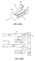
- a terminal of this type has a first and a second contact blades 51 and 52 which are joined at their base 53, and is made by stamping and then bending a metal sheet.
- the first and the second contact blades 51 and 52 extend from the base 53, being parallel to x-axis.
- the first contact blade 51 is formed as a contact: piece which maintains its flat surface, while the second contact blade 52 is bent at its in-between section b2A and its end section 52B against the metal sheet surface.
- the contact blades made in this way, 51 and 52 have almost same length in x-axis direction, as shown in Fig. 4(A).
- the contact blades 51 and 52 have same length (dimension in x-direction), but as for Lhe terminal material with carrier as shown in Fig. 4(B), which is the terminal before bending process, the second contact blade 52 is much longer than the first contact blade 51.
- the original metal strap is required to have a width which is at least equivalent to a distance between the carrier 54 and the end of the longer contact blade 52. Therefore, to stamp the terminal material with the carrier of Fig. 4(B) from a metal strap, there is a lot of waste of the metal sheet due to the large difference between lengths of the contact blades 51 and 52. Therefore, the yield of the material is not satisfactory.
- a terminal 10 in Fiq. 1(A) and (B), has a first contact blade 11 which is pin-shaped and highly rigid, and a second contact blade 12 which is an elastic piece, together,
- the terminal 10 is made by stamping and then bending a metal strap, and the first and the second contact blades 11 and 12 are joined at their bases 11A and 12A, which are angled to be L-shaped, as shown in Fig. 1(B).
- the first contact blade 11 extends leftward from its base 11A, and rounded around its extending axis direction so as to be shaped like a pin.
- the end 11B of the contact blade 11 is a spherical and has a slit 11C so as to gain elasticity at the end 11B in its radius direction.
- a flat base 11A has a staple-shaped groove 11D made by stamping process, and the groove 11D forms a lance 11E which shapes like a tongue piece.
- the lance 11E is formed so as to incline to a thickness direction of the metal sheet, and designed to prevent the terminal from sliding out by engaging between the end of the lance 11E and corresponding engaging section of a housing (not shown) when the terminal 10 is inserted into the housing to assemble.
- the second contact blade 12 shapes like a narrow strip, and extends in the same direction, leftward in Fig. 1(A), with the same length as the first contact blade, and inclines downward.
- the end of the second contact blade forms a contact section 12B which is curved by bending process.
- the second contact blade 12 can elastically deflect upward at the contact section 12B by upward contact pressure at a time of contacting with a substrate.
- the terminal of the present invention is made from a metal strap as illustrated in Fig. 1(C), according to the following procedures.
- the unfinished terminal has a carrier 20, a first plate section 21 and a second plate section 22.
- the carrier 20 extends along a side of the metal strap M, and has engaging holes with certain intervals for feeding.
- the first plate section 21 has the same length as the first contact blade 11 and the same width as the expanded width of the first contact blade 11.
- the first plate section 21 has a round bottom notch 21F at each edge of a section 21A which corresponds to a base 11A in Fig. 1(A), and a groove 11D at its substantially central area.
- the first plate section 21 has two semicircular sections 21B at its left end, having a slit 21C between the circular sections.
- the second plate section 22 extends in the same direction as the first plate section from a section 22A which corresponds to the base 12A in Fig. 1(A), has the same length as the second contact blade in the extending direction, and is slightly tapered towards its end. Therefore, the second plate section 22 has approximately the same length as the first plate section 21.
- “approximately the same length” means that, the first plate section 21 does not have to have exactly the same length as the second plate section 22, and that it does not matter as long as the difference in length between the two plate sections is not so big. In other words, it is an object of the invention to solve wasting of a material, i.e.
- the object of the present invention is fully attained if the difference of the distances is not greater than 15-25%.
- the first plate section 21 and the second plate section 22 are joined at their bases 21A and 22A, which are joined to the carrier via a second base 23.
- the first plate section 21 and the second plate section 22 are paired and are continuously provided to the carrier with certain intervals.
- the unfinished terminal like this is bent with a tool.
- the first plate section 21 is made to a first contact blade 11 by making the first plate section pin-shaped and its end spherical through rounding process, and then inclining a lance 11E.
- the second plate section 22 is made to be the second contact blade 12 which has a contact section 12B, by inclining process at a front end of section 22A which corresponds to a base 12A and by curving process at the end.
- the bases 21A and 22A are angled to L-shape as illustrated in Fig. 1(B) by bending process; thus, a terminal material with a carrier is obtained.
- the obtained terminal material with a carrier is disjoined at a position or single-dotted dash line P in Fig. 1(C), and then inserted to attach to a housing of a connector. Otherwise, after inserting into the housing, it can be cut at the position P so as to disjoin from the carrier.
- the unfinished terminal for the terminal material with the carrier since the unfinished terminal for the terminal material with the carrier has the first plate section 21 and the second plate section 22 which extend in the same direction with approximately the same length, scraps of the metal strap are so small that the yield of the material becomes high.
- a second contact blade 12 is the same as in the first embodiment, but a first contact blade 15 is an elastic piece similar to the second contact blade 12. Since all the parts in this embodiment arc the same as the one illustrated in Fig. 1 except the first contact blade 15, the same reference numbers are used for like parts as in Fig. 1, and the explanations are omitted.
- the first contact blade 15 extends in the same direction as the second contact blade 12 from a base 15A which is perpendicular to a base 12A of the second contact blade 12, maintaining its flat surface.
- the first contact blade 15 has a fixing section 15D adjacent to the base 15A, and the fixing section 15D has engaging protrusions 15E.
- the fixing section 15D is a section to be inserted a corresponding slot (not illustrated) of a housing of a connector for retention, while the engaging protrusions 15E engage the housing to prevent sliding out from the housing.
- the first contact blade 15 of the present invention has a contact section 15B which is made by bending process at a position near the end of the fixing section 15D, and the contact section 15B has a step-like engaging shoulder 15C at its front end.
- the contact section 15B is elastically deflected by a contact pressure from a terminal of its mating connector in perpendicular to a surface of the first contact blade 15, and at this time, the engaging shoulder 15C engages with its corresponding engaging section H of the housing so as to work as a stopper to prevent a greater deflection than the predetermined.
- the first contact blade 15 has a connection section 15F at a side of its base 15A, which faces in opposite direction to the first contact blade 15.
- the connection section 15 shapes like a folk, shares the same surface as that of the base 15A, and has approximately the same width (in a direction perpendicular to the extending direction of the first contact blade 15 in the figure) as the base 15A.
- the unfinished terminal or terminal material with carrier before bonding process is made by stamping a metal strap so as to be shaped as illustrated in Fig. 2(B). Even in the unfinished terminal in Fig. 2(B), the first plate section 25 for the first contact blade 15 and the second plate section 22 for the second contact blade 12 have approximately the same length, so that a metal strap does not have to be wasted so much on stamping process.
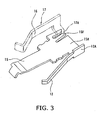
- the terminal according to the present embodiment is used in a manner illustrated in Fig. 3.
- Fig. 3 illustrates an example of use when the terminal with two contact blades 12 and 15 has an additional contact blade, a third contact blade.
- a terminal 17, which is also a third contact blade 16 is held at the housing, and the connection section 17A of the terminal 17 is connected at the folk-shaped connection section 15F. Accordingly, the number of contact blades of the terminal held in a housing can be increased.
- the total number of the contact blades can be four by replacing the terminal 17 with one contact blade, which is illustrated in the figure, to the one with two contact blades. Accordingly, without making a complicated terminal, the terminal can be conveniently adjusted by selecting and connecting other terminal, such as the terminal 17, as necessary, so that it can match with the mating connector. At this time, if a plurality of contact blades have different length, a terminal with same length of contact blades can be made by grouping them together so that a desired contact mode can be attained while it provide a high yield, which is an object of the present invention.
- the contact blade is not limited to the form of an elastic piece, it can take other forms, like pin-shaped as illustrated in Fig. 1(A).
- the terminal has a plurality of contact blades which are joined and extend parallel each other with approximately the same length, so that the yield of the material in the stamping process is improved, that is, resources can be effectively used without wasting.
Description
- The present invention relates to terminals for electrical connectors and terminal material with a carrier.
- It is known to make a terminal with a plurality of contact blades by stamping and bending a metal sheet.
- DE-A-19934119 discloses a connector according to the preamble of claim 1.
- In Fig. 4(A), a terminal of this type has a first and a
second contact blades base 53, and is made by stamping and then bending a metal sheet. The first and thesecond contact blades base 53, being parallel to x-axis. Thefirst contact blade 51 is formed as a contact: piece which maintains its flat surface, while thesecond contact blade 52 is bent at its in-between section b2A and its end section 52B against the metal sheet surface. The contact blades made in this way, 51 and 52, have almost same length in x-axis direction, as shown in Fig. 4(A). - To make the terminal described above, first stamp a long metal strap to make an unfinished terminal, where a number of aforementioned two
contact blades first contact blade 51 by turning upward around x-axis, and thereafter bend thesecond contact blade 52 at the in-betweensection 52A and the end section 52B around y-axis, so as to be formed as illustrated in Fig. 4(A). To put the terminal into a connector, disjoin the terminal from the carrier by cutting at its base so as to be an independent terminal. - In the terminal obtained in this way, the
contact blades second contact blade 52 is much longer than thefirst contact blade 51. - To prepare the terminal material with a carrier before bending process as in Fig. 4(B), the original metal strap is required to have a width which is at least equivalent to a distance between the
carrier 54 and the end of thelonger contact blade 52. Therefore, to stamp the terminal material with the carrier of Fig. 4(B) from a metal strap, there is a lot of waste of the metal sheet due to the large difference between lengths of thecontact blades - Accordingly, it is an object of the invention to provide a terminal and a terminal material with a carrier capable of providing a high yield of material.
- The above object is achieved by the invention as claimed in claim 1. Embodiments of the invention will now be described by way of example with reference to the accompanying drawings in which:
- Fig. 1(A) is a side view of a terminal according to the first embodiment of the invention;
- Fig. 1(B) is a front view of the terminal;
- Fig. 1(C) is a plan view of the terminal material with the carrier;
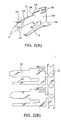
- Fig. 2(A) is a perspective view of a terminal according to the second embodiment of the invention;
- Fig. 2(B) is a plan view of the terminal material with carrier;
- Fig. 3 is a perspective view of the terminal of Fig. 2 when it is used with another terminal or contact blade;
- Fig. 4(A) is a perspective view of a conventional terminal; and
- Fig. 4(B) is a plan view of the terminal material with the carrier.
- In Fiq. 1(A) and (B), a
terminal 10 according to the first embodiment of the invention has afirst contact blade 11 which is pin-shaped and highly rigid, and asecond contact blade 12 which is an elastic piece, together, Theterminal 10 is made by stamping and then bending a metal strap, and the first and thesecond contact blades bases - The
first contact blade 11 extends leftward from itsbase 11A, and rounded around its extending axis direction so as to be shaped like a pin. Theend 11B of thecontact blade 11 is a spherical and has aslit 11C so as to gain elasticity at theend 11B in its radius direction. Also, aflat base 11A has a staple-shaped groove 11D made by stamping process, and thegroove 11D forms alance 11E which shapes like a tongue piece. Thelance 11E is formed so as to incline to a thickness direction of the metal sheet, and designed to prevent the terminal from sliding out by engaging between the end of thelance 11E and corresponding engaging section of a housing (not shown) when theterminal 10 is inserted into the housing to assemble. - The
second contact blade 12 shapes like a narrow strip, and extends in the same direction, leftward in Fig. 1(A), with the same length as the first contact blade, and inclines downward. The end of the second contact blade forms acontact section 12B which is curved by bending process. In Fig. 1(A), thesecond contact blade 12 can elastically deflect upward at thecontact section 12B by upward contact pressure at a time of contacting with a substrate. - The terminal of the present invention is made from a metal strap as illustrated in Fig. 1(C), according to the following procedures.
- First, prepare an elongated metal strap M, as shown by double-dotted dash line in Fig.1 (C). Then, stamp the metal strap to make an unfinished terminal or a terminal material with a carrier as illustrated by solid line in the an exploded view. Here, the unfinished terminal has a
carrier 20, afirst plate section 21 and asecond plate section 22. Thecarrier 20 extends along a side of the metal strap M, and has engaging holes with certain intervals for feeding. - The
first plate section 21 has the same length as thefirst contact blade 11 and the same width as the expanded width of thefirst contact blade 11. Thefirst plate section 21 has around bottom notch 21F at each edge of asection 21A which corresponds to abase 11A in Fig. 1(A), and agroove 11D at its substantially central area. Also, thefirst plate section 21 has twosemicircular sections 21B at its left end, having aslit 21C between the circular sections. - The
second plate section 22 extends in the same direction as the first plate section from asection 22A which corresponds to thebase 12A in Fig. 1(A), has the same length as the second contact blade in the extending direction, and is slightly tapered towards its end. Therefore, thesecond plate section 22 has approximately the same length as thefirst plate section 21. Here, "approximately the same length" means that, thefirst plate section 21 does not have to have exactly the same length as thesecond plate section 22, and that it does not matter as long as the difference in length between the two plate sections is not so big. In other words, it is an object of the invention to solve wasting of a material, i.e. a metal strap, and it is desirable to have smaller difference of distances between a right side edge of thecarrier 20 and the ends of thefirst plate section 21 and thesecond plate section 22. For an example, the object of the present invention is fully attained if the difference of the distances is not greater than 15-25%. - The
first plate section 21 and thesecond plate section 22 are joined at theirbases second base 23. Here, thefirst plate section 21 and thesecond plate section 22 are paired and are continuously provided to the carrier with certain intervals. - The unfinished terminal like this is bent with a tool. Once the unfinished terminal is intermittently fed to the tool position with the
engaging hole 20A of thecarrier 20, thefirst plate section 21 is made to afirst contact blade 11 by making the first plate section pin-shaped and its end spherical through rounding process, and then inclining alance 11E. At the same time, thesecond plate section 22 is made to be thesecond contact blade 12 which has acontact section 12B, by inclining process at a front end ofsection 22A which corresponds to abase 12A and by curving process at the end. At this point, thebases - Then, the obtained terminal material with a carrier is disjoined at a position or single-dotted dash line P in Fig. 1(C), and then inserted to attach to a housing of a connector. Otherwise, after inserting into the housing, it can be cut at the position P so as to disjoin from the carrier.
- As described above, since the unfinished terminal for the terminal material with the carrier has the
first plate section 21 and thesecond plate section 22 which extend in the same direction with approximately the same length, scraps of the metal strap are so small that the yield of the material becomes high. - In Fig. 2(A), according to the second embodiment of the invention, a
second contact blade 12 is the same as in the first embodiment, but afirst contact blade 15 is an elastic piece similar to thesecond contact blade 12. Since all the parts in this embodiment arc the same as the one illustrated in Fig. 1 except thefirst contact blade 15, the same reference numbers are used for like parts as in Fig. 1, and the explanations are omitted. - The
first contact blade 15 extends in the same direction as thesecond contact blade 12 from abase 15A which is perpendicular to abase 12A of thesecond contact blade 12, maintaining its flat surface. Thefirst contact blade 15 has a fixing section 15D adjacent to thebase 15A, and the fixing section 15D has engagingprotrusions 15E. The fixing section 15D is a section to be inserted a corresponding slot (not illustrated) of a housing of a connector for retention, while theengaging protrusions 15E engage the housing to prevent sliding out from the housing. - The
first contact blade 15 of the present invention has a contact section 15B which is made by bending process at a position near the end of the fixing section 15D, and the contact section 15B has a step-likeengaging shoulder 15C at its front end. The contact section 15B is elastically deflected by a contact pressure from a terminal of its mating connector in perpendicular to a surface of thefirst contact blade 15, and at this time, theengaging shoulder 15C engages with its corresponding engaging section H of the housing so as to work as a stopper to prevent a greater deflection than the predetermined. - The
first contact blade 15 has aconnection section 15F at a side of itsbase 15A, which faces in opposite direction to thefirst contact blade 15. Theconnection section 15 shapes like a folk, shares the same surface as that of thebase 15A, and has approximately the same width (in a direction perpendicular to the extending direction of thefirst contact blade 15 in the figure) as thebase 15A. - According to the present invention, the unfinished terminal or terminal material with carrier before bonding process is made by stamping a metal strap so as to be shaped as illustrated in Fig. 2(B). Even in the unfinished terminal in Fig. 2(B), the
first plate section 25 for thefirst contact blade 15 and thesecond plate section 22 for thesecond contact blade 12 have approximately the same length, so that a metal strap does not have to be wasted so much on stamping process. - The terminal according to the present embodiment is used in a manner illustrated in Fig. 3.
- Fig. 3 illustrates an example of use when the terminal with two
contact blades third contact blade 16, is held at the housing, and theconnection section 17A of the terminal 17 is connected at the folk-shapedconnection section 15F. Accordingly, the number of contact blades of the terminal held in a housing can be increased. - Furthermore, the total number of the contact blades can be four by replacing the terminal 17 with one contact blade, which is illustrated in the figure, to the one with two contact blades. Accordingly, without making a complicated terminal, the terminal can be conveniently adjusted by selecting and connecting other terminal, such as the terminal 17, as necessary, so that it can match with the mating connector. At this time, if a plurality of contact blades have different length, a terminal with same length of contact blades can be made by grouping them together so that a desired contact mode can be attained while it provide a high yield, which is an object of the present invention. Furthermore, in this application, the contact blade is not limited to the form of an elastic piece, it can take other forms, like pin-shaped as illustrated in Fig. 1(A).
- As has been described above, according to the present invention, the terminal has a plurality of contact blades which are joined and extend parallel each other with approximately the same length, so that the yield of the material in the stamping process is improved, that is, resources can be effectively used without wasting.
Claims (6)
- A terminal (10) for an electrical connector which is made by stamping and then bending a metal sheet, comprising:a plurality of contact blades (11, 12; 15, 12) which extend in a same direction after they are stamped, and before they are bent join each other at their bases (11A, 12A; 12A, 15A) so as to be one metal sheet, wherein at least one of said contact blades (11, 12; 15, 12) is flexible in a direction perpendicular to an extending direction of other contact blades (11,12; 15, 12) so as to come into contact with a substrate;said terminal (10) being bent at said bases (11A, 12A; 12A, 15A) of said contact blades (11, 12; 15, 12) so that said bases (11A, 12A; 12A, 15A) extend perpendicular from each other ;characterised in that the contact blades have approximately a same length in an extending direction after they are stamped, and before they are bent.
- The terminal (10) according to claim 1, wherein at least one of said contact blades (11, 12; 12, 15) is pin-shaped by rounding in said perpendicular direction.
- The terminal (10) according to claim 1, wherein said plurality of contact blades (11, 12; 12, 15) are flexible and at least one of said contact blades (11, 12; 12, 15) is flexible in a direction perpendicular to other contact blades (11, 12; 12, 15).
- The terminal (10) according to claim 1, at least one of said contact blades (11, 12; 12, 15) has a connection section at its base to connect with another terminal (17).
- A terminal material, comprising:a plurality of said terminals (10) according to claim 1; anda strip-shaped carrier (20) whereby said terminals (10) are joined between their bases and an edge of said carrier (20) with predetermined intervals such that said contact blades (11, 12; 12, 15) extend in a perpendicular direction to said edge of said carrier (20).
- An electrical connector comprising:a housing andat least one terminal (10) according to claim 1 inserted into said housing.
Applications Claiming Priority (2)
| Application Number | Priority Date | Filing Date | Title |
|---|---|---|---|
| JP2001105584A JP2002305068A (en) | 2001-04-04 | 2001-04-04 | Terminal for electric connector, and terminal material with carrier |
| JP2001105584 | 2001-04-04 |
Publications (3)
| Publication Number | Publication Date |
|---|---|
| EP1248324A2 EP1248324A2 (en) | 2002-10-09 |
| EP1248324A3 EP1248324A3 (en) | 2005-01-12 |
| EP1248324B1 true EP1248324B1 (en) | 2006-08-09 |
Family
ID=18958251
Family Applications (1)
| Application Number | Title | Priority Date | Filing Date |
|---|---|---|---|
| EP02007505A Expired - Fee Related EP1248324B1 (en) | 2001-04-04 | 2002-04-02 | Terminal for electrical connector and terminal blank with a carrier |
Country Status (7)
| Country | Link |
|---|---|
| US (1) | US20020146944A1 (en) |
| EP (1) | EP1248324B1 (en) |
| JP (1) | JP2002305068A (en) |
| KR (1) | KR20020079427A (en) |
| CN (1) | CN1379509A (en) |
| DE (1) | DE60213700T2 (en) |
| TW (1) | TW540857U (en) |
Families Citing this family (8)
| Publication number | Priority date | Publication date | Assignee | Title |
|---|---|---|---|---|
| JP2003109718A (en) * | 2001-09-27 | 2003-04-11 | Sumitomo Wiring Syst Ltd | Manufacturing method of male terminal fitting and male terminal fitting |
| US7918876B2 (en) | 2003-03-24 | 2011-04-05 | Theken Spine, Llc | Spinal implant adjustment device |
| JP5094604B2 (en) * | 2008-07-14 | 2012-12-12 | 矢崎総業株式会社 | Inner terminal |
| CN103746208B (en) * | 2014-01-09 | 2017-01-04 | 青岛钜祥精密模具有限公司 | Contact flat spring and method for high-precision manufacturing thereof |
| CN105261603B (en) * | 2015-09-10 | 2018-01-16 | 济南市半导体元件实验所 | High current glass seals Schottky diode and manufacture craft |
| CN108199175B (en) * | 2018-03-12 | 2023-11-24 | 慈溪市佳晶电子有限公司 | Four-pole single-row welding earphone socket and production method thereof |
| CN110277665A (en) * | 2019-07-23 | 2019-09-24 | 宁波三星医疗电气股份有限公司 | Metal contact piece structure, electrical connection module and electronic equipment |
| DE102019134584A1 (en) * | 2019-12-16 | 2021-06-17 | Phoenix Contact Gmbh & Co. Kg | CONTACT ELEMENT FOR CONTACTING ELECTROTECHNICAL COMPONENTS AND ELECTROTECHNICAL COMPONENTS |
Family Cites Families (8)
| Publication number | Priority date | Publication date | Assignee | Title |
|---|---|---|---|---|
| US3631380A (en) * | 1970-03-19 | 1971-12-28 | Patrick A Bohn | Universal circuit board connector |
| US4040705A (en) * | 1976-04-12 | 1977-08-09 | Amp Incorporated | Coaxial ribbon cable connector |
| AU3590378A (en) * | 1978-05-08 | 1978-09-07 | Bunker Ramo | Electrical connector and contact |
| FR2619256B1 (en) * | 1987-08-03 | 1989-12-22 | Souriau & Cie | ELECTRIC CONTACT TERMINAL AND METHOD FOR MANUFACTURING SUCH A TERMINAL |
| JPH0511664Y2 (en) * | 1989-07-19 | 1993-03-23 | ||
| US5310354A (en) * | 1992-03-20 | 1994-05-10 | E. I. Du Pont De Nemours And Company | Integral ground terminal and tail shield |
| US5472358A (en) * | 1994-04-01 | 1995-12-05 | Genrife Company Limited | Contact of single pitch arrangement in strip stock |
| JP3916775B2 (en) * | 1998-08-04 | 2007-05-23 | Smk株式会社 | connector |
-
2001
- 2001-04-04 JP JP2001105584A patent/JP2002305068A/en active Pending
-
2002
- 2002-03-22 US US10/102,893 patent/US20020146944A1/en not_active Abandoned
- 2002-03-25 TW TW091203650U patent/TW540857U/en not_active IP Right Cessation
- 2002-04-02 CN CN02105483A patent/CN1379509A/en active Pending
- 2002-04-02 DE DE60213700T patent/DE60213700T2/en not_active Expired - Fee Related
- 2002-04-02 KR KR1020020018075A patent/KR20020079427A/en not_active Application Discontinuation
- 2002-04-02 EP EP02007505A patent/EP1248324B1/en not_active Expired - Fee Related
Also Published As
| Publication number | Publication date |
|---|---|
| EP1248324A3 (en) | 2005-01-12 |
| JP2002305068A (en) | 2002-10-18 |
| KR20020079427A (en) | 2002-10-19 |
| DE60213700T2 (en) | 2007-08-16 |
| EP1248324A2 (en) | 2002-10-09 |
| US20020146944A1 (en) | 2002-10-10 |
| CN1379509A (en) | 2002-11-13 |
| TW540857U (en) | 2003-07-01 |
| DE60213700D1 (en) | 2006-09-21 |
Similar Documents
| Publication | Publication Date | Title |
|---|---|---|
| CN104659512B (en) | Pin contact for an electrical connector | |
| EP1398852B1 (en) | Electrical connector having a very small contact pitch | |
| JPH08241771A (en) | Electric connector for printed-circuit board installation | |
| IL44589A (en) | Electrical terminal | |
| EP1248324B1 (en) | Terminal for electrical connector and terminal blank with a carrier | |
| US11177589B2 (en) | Electrical terminal and electrical connector thereof | |
| US20090036004A1 (en) | Receptacle terminal | |
| JP2016062836A (en) | Connection structure of connector terminal | |
| CN110581401A (en) | Connection terminal and terminal connection structure | |
| WO2018021057A1 (en) | Female terminal | |
| US11088476B2 (en) | Board connector with chained terminals | |
| US20190148866A1 (en) | Contact element for producing an electric connection with a counterpart element, the electric connection, and windscreen wiper motor | |
| US5807142A (en) | Electrical connector having terminals with improved retention means | |
| US6328585B1 (en) | Electrical connector having a contact element with large flexibility and a short transmission path | |
| JP2017063016A (en) | Electric connection material and electric connector having the same | |
| JP4520874B2 (en) | Female terminals and connectors | |
| KR101032935B1 (en) | A joint connector, a joint terminal, and a production method for joint terminal | |
| EP0638960A2 (en) | Electrical connector having uniform contact receiving slots | |
| EP3799217B1 (en) | Connector and connecting method | |
| US10355386B2 (en) | Electrical connector with contact configured for surface mount | |
| US7303449B2 (en) | Spring bushing for miniature plug-in connectors having contact spring with insertion depth equal to or less than insertion width | |
| US6383038B2 (en) | Connector | |
| EP0930671B1 (en) | Contact with anti-skiving feature | |
| JPH065324A (en) | Connector | |
| US7037145B2 (en) | Electrical contact and connector |
Legal Events
| Date | Code | Title | Description |
|---|---|---|---|
| PUAI | Public reference made under article 153(3) epc to a published international application that has entered the european phase |
Free format text: ORIGINAL CODE: 0009012 |
|
| AK | Designated contracting states |
Kind code of ref document: A2 Designated state(s): AT BE CH CY DE DK ES FI FR GB GR IE IT LI LU MC NL PT SE TR |
|
| AX | Request for extension of the european patent |
Free format text: AL;LT;LV;MK;RO;SI |
|
| PUAL | Search report despatched |
Free format text: ORIGINAL CODE: 0009013 |
|
| AK | Designated contracting states |
Kind code of ref document: A3 Designated state(s): AT BE CH CY DE DK ES FI FR GB GR IE IT LI LU MC NL PT SE TR |
|
| AX | Request for extension of the european patent |
Extension state: AL LT LV MK RO SI |
|
| RIC1 | Information provided on ipc code assigned before grant |
Ipc: 7H 01R 43/16 B Ipc: 7H 01R 13/11 A Ipc: 7H 01R 24/00 B Ipc: 7H 01R 13/24 B |
|
| 17P | Request for examination filed |
Effective date: 20050311 |
|
| 17Q | First examination report despatched |
Effective date: 20050503 |
|
| AKX | Designation fees paid |
Designated state(s): DE FI FR GB |
|
| GRAP | Despatch of communication of intention to grant a patent |
Free format text: ORIGINAL CODE: EPIDOSNIGR1 |
|
| GRAS | Grant fee paid |
Free format text: ORIGINAL CODE: EPIDOSNIGR3 |
|
| GRAA | (expected) grant |
Free format text: ORIGINAL CODE: 0009210 |
|
| AK | Designated contracting states |
Kind code of ref document: B1 Designated state(s): DE FI FR GB |
|
| REG | Reference to a national code |
Ref country code: GB Ref legal event code: FG4D |
|
| REF | Corresponds to: |
Ref document number: 60213700 Country of ref document: DE Date of ref document: 20060921 Kind code of ref document: P |
|
| ET | Fr: translation filed | ||
| PGFP | Annual fee paid to national office [announced via postgrant information from national office to epo] |
Ref country code: GB Payment date: 20070328 Year of fee payment: 6 |
|
| PGFP | Annual fee paid to national office [announced via postgrant information from national office to epo] |
Ref country code: DE Payment date: 20070430 Year of fee payment: 6 |
|
| PLBE | No opposition filed within time limit |
Free format text: ORIGINAL CODE: 0009261 |
|
| STAA | Information on the status of an ep patent application or granted ep patent |
Free format text: STATUS: NO OPPOSITION FILED WITHIN TIME LIMIT |
|
| 26N | No opposition filed |
Effective date: 20070510 |
|
| PGFP | Annual fee paid to national office [announced via postgrant information from national office to epo] |
Ref country code: FR Payment date: 20070316 Year of fee payment: 6 |
|
| GBPC | Gb: european patent ceased through non-payment of renewal fee |
Effective date: 20080402 |
|
| PG25 | Lapsed in a contracting state [announced via postgrant information from national office to epo] |
Ref country code: DE Free format text: LAPSE BECAUSE OF NON-PAYMENT OF DUE FEES Effective date: 20081101 |
|
| REG | Reference to a national code |
Ref country code: FR Ref legal event code: ST Effective date: 20081231 |
|
| PG25 | Lapsed in a contracting state [announced via postgrant information from national office to epo] |
Ref country code: FR Free format text: LAPSE BECAUSE OF NON-PAYMENT OF DUE FEES Effective date: 20080430 |
|
| PG25 | Lapsed in a contracting state [announced via postgrant information from national office to epo] |
Ref country code: GB Free format text: LAPSE BECAUSE OF NON-PAYMENT OF DUE FEES Effective date: 20080402 |
|
| PGFP | Annual fee paid to national office [announced via postgrant information from national office to epo] |
Ref country code: FI Payment date: 20090420 Year of fee payment: 8 |
|
| PG25 | Lapsed in a contracting state [announced via postgrant information from national office to epo] |
Ref country code: FI Free format text: LAPSE BECAUSE OF NON-PAYMENT OF DUE FEES Effective date: 20100402 |