EP1248054A2 - Wärmezelle eines Heizgerätes - Google Patents
Wärmezelle eines Heizgerätes Download PDFInfo
- Publication number
- EP1248054A2 EP1248054A2 EP02006328A EP02006328A EP1248054A2 EP 1248054 A2 EP1248054 A2 EP 1248054A2 EP 02006328 A EP02006328 A EP 02006328A EP 02006328 A EP02006328 A EP 02006328A EP 1248054 A2 EP1248054 A2 EP 1248054A2
- Authority
- EP
- European Patent Office
- Prior art keywords
- removable
- flow
- heating shaft
- side wall
- heat
- Prior art date
- Legal status (The legal status is an assumption and is not a legal conclusion. Google has not performed a legal analysis and makes no representation as to the accuracy of the status listed.)
- Granted
Links
Images

Classifications
-
- F—MECHANICAL ENGINEERING; LIGHTING; HEATING; WEAPONS; BLASTING
- F24—HEATING; RANGES; VENTILATING
- F24H—FLUID HEATERS, e.g. WATER OR AIR HEATERS, HAVING HEAT-GENERATING MEANS, e.g. HEAT PUMPS, IN GENERAL
- F24H1/00—Water heaters, e.g. boilers, continuous-flow heaters or water-storage heaters
- F24H1/10—Continuous-flow heaters, i.e. heaters in which heat is generated only while the water is flowing, e.g. with direct contact of the water with the heating medium
- F24H1/12—Continuous-flow heaters, i.e. heaters in which heat is generated only while the water is flowing, e.g. with direct contact of the water with the heating medium in which the water is kept separate from the heating medium
- F24H1/14—Continuous-flow heaters, i.e. heaters in which heat is generated only while the water is flowing, e.g. with direct contact of the water with the heating medium in which the water is kept separate from the heating medium by tubes, e.g. bent in serpentine form
- F24H1/145—Continuous-flow heaters, i.e. heaters in which heat is generated only while the water is flowing, e.g. with direct contact of the water with the heating medium in which the water is kept separate from the heating medium by tubes, e.g. bent in serpentine form using fluid fuel
-
- F—MECHANICAL ENGINEERING; LIGHTING; HEATING; WEAPONS; BLASTING
- F24—HEATING; RANGES; VENTILATING
- F24H—FLUID HEATERS, e.g. WATER OR AIR HEATERS, HAVING HEAT-GENERATING MEANS, e.g. HEAT PUMPS, IN GENERAL
- F24H9/00—Details
- F24H9/14—Arrangements for connecting different sections, e.g. in water heaters
-
- F—MECHANICAL ENGINEERING; LIGHTING; HEATING; WEAPONS; BLASTING
- F24—HEATING; RANGES; VENTILATING
- F24H—FLUID HEATERS, e.g. WATER OR AIR HEATERS, HAVING HEAT-GENERATING MEANS, e.g. HEAT PUMPS, IN GENERAL
- F24H9/00—Details
- F24H9/14—Arrangements for connecting different sections, e.g. in water heaters
- F24H9/146—Connecting elements of a heat exchanger
Definitions
- the invention relates to a heat cell according to the preamble of the independent Claim.
- the Flow assurance formed as a circumferentially closed component that on the Heat exchanger is set.
- Known heating shafts have a removable side wall so that e.g. the Burner top and the heat exchanger underside after removing this side wall can be cleaned.
- cleaning the top of the heat exchanger is only possible if the complete flow safety device or the heat exchanger is removed.
- this is associated with a very considerable installation effort, with one Disassembly of the heat exchanger drains a room heater connected to it must become.
- the aim of the invention is to avoid these disadvantages and a heat cell of the beginning Propose the kind mentioned, which is characterized by a high degree of ease of maintenance distinguished and in particular a simple way of cleaning the heat exchanger allows.
- the proposed measures make it possible in a simple manner by acceptance to clean both the burner and the heat exchanger of the removable unit, because these parts are easily accessible. It is also possible to use both the sub and the Clean the top of the heat exchanger.
- the measures according to claim 2 have the advantage of being constructive Regarding very simple solution.
- the removable unit can be very simple assembled and disassembled.
- the flow of the exhaust gases can be very simple can be influenced, with the unit installed in terms of flow there is practically no difference to a flow control according to the prior art, which is designed to be circumferentially closed.
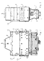
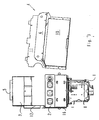
- a heat cell 13 comprises a heating shaft 14 in which a burner 1 is arranged, a heat exchanger arranged above the burner 1 in the heating shaft 14 2, and a flow safety device 3 arranged above the heating shaft 14 Heater shaft 14 and the flow control 3 connected together.
- the heating shaft 14 is essentially of two side walls 15, a rear wall 16 and limited a removable front wall 10.
- the above the heat exchanger 2 The arranged flow protection device 3 is the one with the heating shaft 14 via a rear wall 12 connected.
- the rear wall 12 of the flow safety device 3 is expediently included the rear wall 16 of the heating shaft 14 connected, or are made of a sheet metal part.
- the flow control 3 closes at the top with the exhaust connection 5 and has lateral openings 17. To the front is the flow safety device 3 through the front wall 11 completed.
- the stop 6 lies on the rear wall 12 of the flow safety device 3 on, the latching lugs 7 latching into notches 8 in the rear wall 12.
- Unit 4 is screwed to the side walls 15 in the assembled state.
- the unit After disassembling the connecting screws used to connect the unit 4 to the Side walls 15 are provided, the unit can be pulled out of the heat cell. Thereafter, both the burner 1 and the heat exchanger 2 are very accessible and can be easily cleaned.
Landscapes
- Engineering & Computer Science (AREA)
- Physics & Mathematics (AREA)
- Thermal Sciences (AREA)
- Chemical & Material Sciences (AREA)
- Combustion & Propulsion (AREA)
- Mechanical Engineering (AREA)
- General Engineering & Computer Science (AREA)
- Gas Burners (AREA)
- Battery Mounting, Suspending (AREA)
- Fuel Cell (AREA)
- Thermotherapy And Cooling Therapy Devices (AREA)
- Details Of Fluid Heaters (AREA)
Abstract
Description
Claims (5)
- Wärmezelle (13) eines Heizgerätes bestehend zumindest aus einem Brenner (1), einem diesen und einen Wärmetauscher (2) aufnehmenden Heizschacht (14), der mindestens eine demontierbare Seitenwand (10) aufweist, und einer den Heizschacht überdeckenden Strömungssicherung (3), dadurch gekennzeichnet, dass die demontierbare Seitenwand (10) des Heizschachtes (14) mit einer demontierbaren Seitenwand (11) der Strömungssicherung (3) eine gemeinsame, demontierbare Einheit (4) bildet.
- Wärmezelle nach Anspruch 1, dadurch gekennzeichnet, daß der Heizschacht (14) und die Strömungssicherung (3) an der jeweils gleichen Seite mit einer demontierbaren Seitenwand (10, 11) begrenzt sind.
- Wärmezelle (13) nach Anspruch 1 oder 2, dadurch gekennzeichnet, dass die demontierbare Einheit (4) über einen Anschlag (6), der an der gegenüberliegenden Seite, vorzugsweise Rückwand (12) der Strömungssicherung (3) anliegt, verfügt.
- Wärmezelle (13) nach Anspruch 3, dadurch gekennzeichnet, dass der Anschlag (6) mittels Einrastnasen (7) in an der Rückwand (12) angeordnete Einrastkerben (8) einrastet.
- Wärmezelle (13) nach einem der Ansprüche 1 bis 4, dadurch gekennzeichnet, dass die demontierbare Einheit (4) Strömungsleitbleche (9) aufweist, die im wesentlichen senkrecht von den demontierbaren Seitenwänden (10, 11) abstehen.
Applications Claiming Priority (4)
| Application Number | Priority Date | Filing Date | Title |
|---|---|---|---|
| DE10114792 | 2001-03-26 | ||
| DE10114792 | 2001-03-26 | ||
| AT0107001A AT410839B (de) | 2001-07-10 | 2001-07-10 | Wärmezelle eines heizgerätes |
| AT10702001 | 2001-07-10 |
Publications (3)
| Publication Number | Publication Date |
|---|---|
| EP1248054A2 true EP1248054A2 (de) | 2002-10-09 |
| EP1248054A3 EP1248054A3 (de) | 2003-09-10 |
| EP1248054B1 EP1248054B1 (de) | 2005-12-28 |
Family
ID=25608489
Family Applications (1)
| Application Number | Title | Priority Date | Filing Date |
|---|---|---|---|
| EP02006328A Expired - Lifetime EP1248054B1 (de) | 2001-03-26 | 2002-03-21 | Wärmezelle eines Heizgerätes |
Country Status (4)
| Country | Link |
|---|---|
| EP (1) | EP1248054B1 (de) |
| AT (1) | ATE314616T1 (de) |
| DE (2) | DE50205397D1 (de) |
| ES (1) | ES2255586T3 (de) |
Family Cites Families (1)
| Publication number | Priority date | Publication date | Assignee | Title |
|---|---|---|---|---|
| DE29702137U1 (de) * | 1997-02-08 | 1997-04-10 | Viessmann Werke Gmbh & Co, 35108 Allendorf | Wandtherme |
-
2002
- 2002-03-21 DE DE50205397T patent/DE50205397D1/de not_active Expired - Lifetime
- 2002-03-21 EP EP02006328A patent/EP1248054B1/de not_active Expired - Lifetime
- 2002-03-21 ES ES02006328T patent/ES2255586T3/es not_active Expired - Lifetime
- 2002-03-21 AT AT02006328T patent/ATE314616T1/de active
- 2002-03-22 DE DE10214214A patent/DE10214214A1/de not_active Withdrawn
Also Published As
| Publication number | Publication date |
|---|---|
| DE50205397D1 (de) | 2006-02-02 |
| EP1248054A3 (de) | 2003-09-10 |
| ES2255586T3 (es) | 2006-07-01 |
| DE10214214A1 (de) | 2002-10-31 |
| EP1248054B1 (de) | 2005-12-28 |
| ATE314616T1 (de) | 2006-01-15 |
Similar Documents
| Publication | Publication Date | Title |
|---|---|---|
| EP2312953B1 (de) | Backofen mit schwadenapparat | |
| EP0309838A1 (de) | Gasbrenner | |
| DE4207500C2 (de) | Heizkessel mit verringerter NO¶x¶-Emission | |
| DE3633236C2 (de) | ||
| DE3012588C2 (de) | Strahlungsbrenner, insbesondere für gasförmigen Brennstoff | |
| EP2051006A1 (de) | Heizgerät | |
| DE3831624A1 (de) | Gasbrenner | |
| AT410839B (de) | Wärmezelle eines heizgerätes | |
| EP1248054B1 (de) | Wärmezelle eines Heizgerätes | |
| EP3124869B1 (de) | Luftauslassgitter, insbesondere für einen ofen | |
| DE202007006228U1 (de) | Ofen für feste Brennstoffe | |
| DE2929715C2 (de) | Warmluftofen für feste Brennstoffe | |
| DE3113418C2 (de) | ||
| EP0617244B1 (de) | Luftheizgerät | |
| DE29822930U1 (de) | Deckenluftdurchlaß für klimatechnische Anlagen | |
| DE69001197T2 (de) | Kesselglied fuer niedertemperatur-heizkessel. | |
| EP0153611A2 (de) | Gasheizkessel mit Brenner ohne Gebläse | |
| DE202022100851U1 (de) | Gasgrill | |
| AT399381B (de) | Gussgliederkessel | |
| DE10113589A1 (de) | Heizkörper | |
| AT402849B (de) | Strömungssicherung | |
| EP0617242A2 (de) | Dreizugheizkessel | |
| AT411102B (de) | Brennwert-heizgerät | |
| DE3307598A1 (de) | Bauelement zur fertigung einer heizungsanlage und unter verwendung solcher bauelemente gefertigte heinzunganlage | |
| DE1900004A1 (de) | Brennkammer fuer Heizgeraete,insbesondere Gasluftheizgeraete |
Legal Events
| Date | Code | Title | Description |
|---|---|---|---|
| PUAI | Public reference made under article 153(3) epc to a published international application that has entered the european phase |
Free format text: ORIGINAL CODE: 0009012 |
|
| AK | Designated contracting states |
Kind code of ref document: A2 Designated state(s): AT BE CH CY DE DK ES FI FR GB GR IE IT LI LU MC NL PT SE TR |
|
| AX | Request for extension of the european patent |
Free format text: AL;LT;LV;MK;RO;SI |
|
| PUAL | Search report despatched |
Free format text: ORIGINAL CODE: 0009013 |
|
| AK | Designated contracting states |
Kind code of ref document: A3 Designated state(s): AT BE CH CY DE DK ES FI FR GB GR IE IT LI LU MC NL PT SE TR |
|
| AX | Request for extension of the european patent |
Extension state: AL LT LV MK RO SI |
|
| 17P | Request for examination filed |
Effective date: 20040205 |
|
| AKX | Designation fees paid |
Designated state(s): AT BE CH CY DE DK ES FI FR GB GR IE IT LI LU MC NL PT SE TR |
|
| GRAP | Despatch of communication of intention to grant a patent |
Free format text: ORIGINAL CODE: EPIDOSNIGR1 |
|
| GRAS | Grant fee paid |
Free format text: ORIGINAL CODE: EPIDOSNIGR3 |
|
| GRAA | (expected) grant |
Free format text: ORIGINAL CODE: 0009210 |
|
| RTI1 | Title (correction) |
Free format text: THERMAL CELL OF A HEATER |
|
| AK | Designated contracting states |
Kind code of ref document: B1 Designated state(s): AT BE CH CY DE DK ES FI FR GB GR IE IT LI LU MC NL PT SE TR |
|
| PG25 | Lapsed in a contracting state [announced via postgrant information from national office to epo] |
Ref country code: IE Free format text: LAPSE BECAUSE OF FAILURE TO SUBMIT A TRANSLATION OF THE DESCRIPTION OR TO PAY THE FEE WITHIN THE PRESCRIBED TIME-LIMIT Effective date: 20051228 Ref country code: NL Free format text: LAPSE BECAUSE OF FAILURE TO SUBMIT A TRANSLATION OF THE DESCRIPTION OR TO PAY THE FEE WITHIN THE PRESCRIBED TIME-LIMIT Effective date: 20051228 Ref country code: GB Free format text: LAPSE BECAUSE OF FAILURE TO SUBMIT A TRANSLATION OF THE DESCRIPTION OR TO PAY THE FEE WITHIN THE PRESCRIBED TIME-LIMIT Effective date: 20051228 Ref country code: FI Free format text: LAPSE BECAUSE OF FAILURE TO SUBMIT A TRANSLATION OF THE DESCRIPTION OR TO PAY THE FEE WITHIN THE PRESCRIBED TIME-LIMIT Effective date: 20051228 |
|
| REG | Reference to a national code |
Ref country code: GB Ref legal event code: FG4D Free format text: NOT ENGLISH |
|
| REG | Reference to a national code |
Ref country code: CH Ref legal event code: EP |
|
| REG | Reference to a national code |
Ref country code: IE Ref legal event code: FG4D Free format text: LANGUAGE OF EP DOCUMENT: GERMAN |
|
| REF | Corresponds to: |
Ref document number: 50205397 Country of ref document: DE Date of ref document: 20060202 Kind code of ref document: P |
|
| PG25 | Lapsed in a contracting state [announced via postgrant information from national office to epo] |
Ref country code: SE Free format text: LAPSE BECAUSE OF FAILURE TO SUBMIT A TRANSLATION OF THE DESCRIPTION OR TO PAY THE FEE WITHIN THE PRESCRIBED TIME-LIMIT Effective date: 20060328 Ref country code: DK Free format text: LAPSE BECAUSE OF FAILURE TO SUBMIT A TRANSLATION OF THE DESCRIPTION OR TO PAY THE FEE WITHIN THE PRESCRIBED TIME-LIMIT Effective date: 20060328 |
|
| PG25 | Lapsed in a contracting state [announced via postgrant information from national office to epo] |
Ref country code: LU Free format text: LAPSE BECAUSE OF NON-PAYMENT OF DUE FEES Effective date: 20060331 Ref country code: MC Free format text: LAPSE BECAUSE OF NON-PAYMENT OF DUE FEES Effective date: 20060331 |
|
| REG | Reference to a national code |
Ref country code: GR Ref legal event code: EP Ref document number: 20060401016 Country of ref document: GR |
|
| NLV1 | Nl: lapsed or annulled due to failure to fulfill the requirements of art. 29p and 29m of the patents act | ||
| REG | Reference to a national code |
Ref country code: ES Ref legal event code: FG2A Ref document number: 2255586 Country of ref document: ES Kind code of ref document: T3 |
|
| GBV | Gb: ep patent (uk) treated as always having been void in accordance with gb section 77(7)/1977 [no translation filed] |
Effective date: 20051228 |
|
| REG | Reference to a national code |
Ref country code: IE Ref legal event code: FD4D |
|
| ET | Fr: translation filed | ||
| PLBE | No opposition filed within time limit |
Free format text: ORIGINAL CODE: 0009261 |
|
| STAA | Information on the status of an ep patent application or granted ep patent |
Free format text: STATUS: NO OPPOSITION FILED WITHIN TIME LIMIT |
|
| 26N | No opposition filed |
Effective date: 20060929 |
|
| PG25 | Lapsed in a contracting state [announced via postgrant information from national office to epo] |
Ref country code: GR Free format text: LAPSE BECAUSE OF NON-PAYMENT OF DUE FEES Effective date: 20060329 |
|
| PG25 | Lapsed in a contracting state [announced via postgrant information from national office to epo] |
Ref country code: CY Free format text: LAPSE BECAUSE OF FAILURE TO SUBMIT A TRANSLATION OF THE DESCRIPTION OR TO PAY THE FEE WITHIN THE PRESCRIBED TIME-LIMIT Effective date: 20051228 |
|
| REG | Reference to a national code |
Ref country code: FR Ref legal event code: PLFP Year of fee payment: 15 |
|
| PGFP | Annual fee paid to national office [announced via postgrant information from national office to epo] |
Ref country code: CH Payment date: 20160304 Year of fee payment: 15 Ref country code: ES Payment date: 20160119 Year of fee payment: 15 |
|
| PGFP | Annual fee paid to national office [announced via postgrant information from national office to epo] |
Ref country code: BE Payment date: 20160307 Year of fee payment: 15 Ref country code: AT Payment date: 20160302 Year of fee payment: 15 Ref country code: PT Payment date: 20160208 Year of fee payment: 15 |
|
| PGFP | Annual fee paid to national office [announced via postgrant information from national office to epo] |
Ref country code: IT Payment date: 20160331 Year of fee payment: 15 |
|
| REG | Reference to a national code |
Ref country code: FR Ref legal event code: PLFP Year of fee payment: 16 |
|
| REG | Reference to a national code |
Ref country code: CH Ref legal event code: PL |
|
| REG | Reference to a national code |
Ref country code: AT Ref legal event code: MM01 Ref document number: 314616 Country of ref document: AT Kind code of ref document: T Effective date: 20170321 |
|
| PG25 | Lapsed in a contracting state [announced via postgrant information from national office to epo] |
Ref country code: PT Free format text: LAPSE BECAUSE OF NON-PAYMENT OF DUE FEES Effective date: 20170921 |
|
| PG25 | Lapsed in a contracting state [announced via postgrant information from national office to epo] |
Ref country code: AT Free format text: LAPSE BECAUSE OF NON-PAYMENT OF DUE FEES Effective date: 20170321 |
|
| PG25 | Lapsed in a contracting state [announced via postgrant information from national office to epo] |
Ref country code: LI Free format text: LAPSE BECAUSE OF NON-PAYMENT OF DUE FEES Effective date: 20170331 Ref country code: CH Free format text: LAPSE BECAUSE OF NON-PAYMENT OF DUE FEES Effective date: 20170331 Ref country code: IT Free format text: LAPSE BECAUSE OF NON-PAYMENT OF DUE FEES Effective date: 20170321 |
|
| REG | Reference to a national code |
Ref country code: BE Ref legal event code: MM Effective date: 20170331 |
|
| REG | Reference to a national code |
Ref country code: FR Ref legal event code: PLFP Year of fee payment: 17 |
|
| PG25 | Lapsed in a contracting state [announced via postgrant information from national office to epo] |
Ref country code: BE Free format text: LAPSE BECAUSE OF NON-PAYMENT OF DUE FEES Effective date: 20170331 |
|
| REG | Reference to a national code |
Ref country code: ES Ref legal event code: FD2A Effective date: 20180703 |
|
| PG25 | Lapsed in a contracting state [announced via postgrant information from national office to epo] |
Ref country code: ES Free format text: LAPSE BECAUSE OF NON-PAYMENT OF DUE FEES Effective date: 20170322 |
|
| PGFP | Annual fee paid to national office [announced via postgrant information from national office to epo] |
Ref country code: FR Payment date: 20210323 Year of fee payment: 20 |
|
| PGFP | Annual fee paid to national office [announced via postgrant information from national office to epo] |
Ref country code: DE Payment date: 20210301 Year of fee payment: 20 Ref country code: TR Payment date: 20210301 Year of fee payment: 20 |
|
| REG | Reference to a national code |
Ref country code: DE Ref legal event code: R071 Ref document number: 50205397 Country of ref document: DE |
|
| PG25 | Lapsed in a contracting state [announced via postgrant information from national office to epo] |
Ref country code: TR Free format text: LAPSE BECAUSE OF NON-PAYMENT OF DUE FEES Effective date: 20220321 |