EP1248028A1 - Raccord etanche - Google Patents
Raccord etanche Download PDFInfo
- Publication number
- EP1248028A1 EP1248028A1 EP02290796A EP02290796A EP1248028A1 EP 1248028 A1 EP1248028 A1 EP 1248028A1 EP 02290796 A EP02290796 A EP 02290796A EP 02290796 A EP02290796 A EP 02290796A EP 1248028 A1 EP1248028 A1 EP 1248028A1
- Authority
- EP
- European Patent Office
- Prior art keywords
- insert
- housing
- bead
- rigid
- intended
- Prior art date
- Legal status (The legal status is an assumption and is not a legal conclusion. Google has not performed a legal analysis and makes no representation as to the accuracy of the status listed.)
- Granted
Links
- 230000008878 coupling Effects 0.000 title 1
- 238000010168 coupling process Methods 0.000 title 1
- 238000005859 coupling reaction Methods 0.000 title 1
- 239000011324 bead Substances 0.000 claims description 26
- 238000007789 sealing Methods 0.000 claims description 16
- 229920001971 elastomer Polymers 0.000 claims description 13
- 239000000806 elastomer Substances 0.000 claims description 11
- 239000000463 material Substances 0.000 claims description 8
- 230000002787 reinforcement Effects 0.000 claims description 2
- 230000006835 compression Effects 0.000 description 2
- 238000007906 compression Methods 0.000 description 2
- 239000012530 fluid Substances 0.000 description 2
- RRHGJUQNOFWUDK-UHFFFAOYSA-N Isoprene Chemical compound CC(=C)C=C RRHGJUQNOFWUDK-UHFFFAOYSA-N 0.000 description 1
- 229920000914 Metallic fiber Polymers 0.000 description 1
- 229910000831 Steel Inorganic materials 0.000 description 1
- XAGFODPZIPBFFR-UHFFFAOYSA-N aluminium Chemical compound [Al] XAGFODPZIPBFFR-UHFFFAOYSA-N 0.000 description 1
- 229910052782 aluminium Inorganic materials 0.000 description 1
- 239000006185 dispersion Substances 0.000 description 1
- 239000003365 glass fiber Substances 0.000 description 1
- 239000007788 liquid Substances 0.000 description 1
- 238000004519 manufacturing process Methods 0.000 description 1
- 239000002557 mineral fiber Substances 0.000 description 1
- 230000002093 peripheral effect Effects 0.000 description 1
- 239000004033 plastic Substances 0.000 description 1
- 229920001195 polyisoprene Polymers 0.000 description 1
- 239000011347 resin Substances 0.000 description 1
- 229920005989 resin Polymers 0.000 description 1
- 230000000284 resting effect Effects 0.000 description 1
- 125000006850 spacer group Chemical group 0.000 description 1
- 239000010959 steel Substances 0.000 description 1
- 229920002994 synthetic fiber Polymers 0.000 description 1
Images

Classifications
-
- F—MECHANICAL ENGINEERING; LIGHTING; HEATING; WEAPONS; BLASTING
- F16—ENGINEERING ELEMENTS AND UNITS; GENERAL MEASURES FOR PRODUCING AND MAINTAINING EFFECTIVE FUNCTIONING OF MACHINES OR INSTALLATIONS; THERMAL INSULATION IN GENERAL
- F16L—PIPES; JOINTS OR FITTINGS FOR PIPES; SUPPORTS FOR PIPES, CABLES OR PROTECTIVE TUBING; MEANS FOR THERMAL INSULATION IN GENERAL
- F16L23/00—Flanged joints
- F16L23/16—Flanged joints characterised by the sealing means
- F16L23/18—Flanged joints characterised by the sealing means the sealing means being rings
-
- F—MECHANICAL ENGINEERING; LIGHTING; HEATING; WEAPONS; BLASTING
- F16—ENGINEERING ELEMENTS AND UNITS; GENERAL MEASURES FOR PRODUCING AND MAINTAINING EFFECTIVE FUNCTIONING OF MACHINES OR INSTALLATIONS; THERMAL INSULATION IN GENERAL
- F16L—PIPES; JOINTS OR FITTINGS FOR PIPES; SUPPORTS FOR PIPES, CABLES OR PROTECTIVE TUBING; MEANS FOR THERMAL INSULATION IN GENERAL
- F16L23/00—Flanged joints
- F16L23/16—Flanged joints characterised by the sealing means
Definitions
- the present invention relates to fittings waterproof.
- the invention relates to a tight fitting intended to connect arranged channels to each other respectively in first and second rigid parts secured to each other, this tight fitting comprising at least one tubular insert which includes a frame rigid tubular extending axially between first and second open ends, said first and second ends being respectively coated with first and second elastomeric beads which project axially beyond the corresponding end of the reinforcement tubular.
- this fluid may be the oil circulating under a variable pressure, possibly pulsating, from 0 to several tens bars, also at very variable temperature (- 40 to + 150 ° C for example).
- the parts in question may belong to housings, especially in a gearbox automatic.
- the object of the present invention is in particular to overcome these drawbacks.
- a connection of the kind in question is characterized in that it further comprises a rigid intermediate block with first and second opposite faces into which a conduit opens crossing said intermediate block, the first face being with a sealing device adapted to come into waterproof support against the first rigid part by insulating said conduit, the conduit forming a cylindrical housing which extends between the second face of the intermediate block and a shoulder oriented towards said second face, and the insert tubular being disposed in said housing with its first bead in sealed axial support against the shoulder of said housing and its second bead projecting out of the housing, this second bead being intended to come in waterproof support against the second rigid part.
- Rooms 1 and 2 are crossed by channels 5, and 6 strongly offset one with respect to each other ( Figure 1), which are connected to each other so sealed by a fitting comprising an intermediate block rigid 3, in particular in steel.
- This intermediate block 3 is crossed by at least one conduit comprising two sections 4a, 4b with a diameter greater than that of channels 5, 6 and opening respectively into these channels formed in the parts 1 and / or 2.
- the intermediate block 3 may also be made for example of aluminum, plastic (resin of type PA 6-6 or PPS, possibly loaded with glass fibers or the like), or the like.
- One of the faces 7, 8 of the intermediate block 3 which is intended to come into abutment during assembly against one of the support faces 9, 10 of the part 1 (or of the part 2) comprises a sealing device 11, constituted for example by a overmolded elastomer ring, in line with the opening emerging from the conduit 4a.
- the other face 8 of the intermediate block 3 which is intended to bear against one of the bearing faces 9, 10 of Exhibit 2 (or Exhibit 1) has a second sealing device 12.
- the rigid tubular frame 14 outside or inside of insert 13 will prevent any significant deformation, in particular any expansion, of the rubber 15 inside or outside sealing the passage.
- the ends of this frame will serve as support for the end beads (15 ', 15' ') of the tube 15, tablets between part 1 or 2 and shoulder 16 produced in the conduit 4a, 4b of the intermediate block 3, this which will maintain the seal at the ends of the fitting waterproof.
- the tubular frame 14 could advantageously be metallic, produced in massive form or even under the form of a braid of metallic threads or mineral fibers or synthetic, if it does not have to be submitted to axial compression forces.
- FIG. 2 which can be substituted for the sealing device 11 (the elastomer ring), a second sealing device 12 (tubular insert), the latter being inserted in a housing of the conduit 4a and resting on one of its beads 15 ', 15' ', at a shoulder.
- the sealing device 11 the elastomer ring
- a second sealing device 12 tubular insert
- connection device identical to that shown in figure 1, but which makes it possible to connect in a sealed manner channels 5a and 5b of the part 1 very close to channels 6a, 6b located in room 2.
- the thickness of the inserts 13 (measured at rest, that is to say that the end beads are not compressed) is greater than the depth of the housing in which comes house said insert, so that when parts 1 and 2 are brought together, the compression of bulges (15 ', 15' ') compensates, as is found in in practice, a large dispersion of block thicknesses intermediate 3, as well as variable play between it and parts 1 and / or 2.
- a positioning device 17 adapted to cooperate by interlocking with at least one of the first and second rigid parts 1, 2. It can be a pawn 18 making projection from the front face 7 or 8 of the block intermediate 3, the latter cooperating at an orifice 18 made on one of parts 1 or 2.
- an outgrowth of material 20, especially in elastomer, came from manufacturing with one beads 15 ', 15' 'located at the end of the insert 13.
- this outgrowth of material 20 is produced on the peripheral external surface of the insert 13 and came during overmolding.
- the protuberance of material 20 is formed by a lip located to the right of the outlet orifice of the housing receiving the insert 13.
- the outgrowth of material 20 generates friction between the insert 13 and a wall of the duct 4a, 4b in which it is housed, thus limiting the movement of the latter.
Landscapes
- Engineering & Computer Science (AREA)
- General Engineering & Computer Science (AREA)
- Mechanical Engineering (AREA)
- Quick-Acting Or Multi-Walled Pipe Joints (AREA)
- Gasket Seals (AREA)
- Non-Reversible Transmitting Devices (AREA)
- Details Of Aerials (AREA)
- Cable Accessories (AREA)
- Outer Garments And Coats (AREA)
Abstract
Description
- le bourrelet de l'insert comporte en périphérie une excroissance de matière destinée à limiter le coulissement de l'insert dans son logement ;
- le logement comporte en périphérie une excroissance de matière destinée à limiter le coulissement de l'insert ;
- le dispositif d'étanchéité est un anneau en élastomère surmoulé sur l'une des faces du bloc intermédiaire ;
- le dispositif d'étanchéité est un insert tubulaire logé dans un logement formé dans un conduit, ledit insert comprenant une armature tubulaire rigide s'étendant axialement entre des première et deuxième extrémités ouvertes revêtues respectivement de premier et deuxième bourrelets d'élastomère, le premier bourrelet étant en appui d'un épaulement formé dans le logement et le deuxième bourrelet étant destiné à venir en appui étanche contre la première pièce rigide ;
- le bloc intermédiaire comporte, sur au moins l'une des faces destinées à venir en appui de l'une des première ou seconde pièces, un dispositif de positionnement adapté pour coopérer par emboítement avec au moins l'une des première et deuxième pièces rigides ;
- l'armature tubulaire de l'insert est revêtue d'une couche continue d'élastomère qui est formée d'une seule pièce avec les premier et deuxième bourrelets ;
- le premier bourrelet d'élastomère est compressible élastiquement sur une distance axiale d'au moins 5 mm.
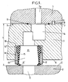
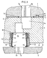
- les figures 1, 2, 3 sont des vues en élévation latérale de trois modes de réalisation différents du raccord étanche objet de l'invention ;
- les figures 4 et 5 sont des vues en détail de l'un des dispositifs d'étanchéité du raccord étanche représenté en figures 1, 2, 3 ;
- la figure 6 est une vue en détail du bord d'un des logements recevant l'insert, formant le dispositif d'étanchéité du raccord étanche.
- une armature tubulaire rigide 14; et
- au moins un tube 15 en caoutchouc ou matière synthétique élastique, revêtant au moins les extrémités de ladite armature et présentant à ses deux extrémités un premier et second bourrelet (15', 15'') recouvrant l'extrémité correspondante de cette armature, ces premier et second bourrelets pouvant ainsi être comprimés (de l'ordre par exemple de 5mm), lors du montage, de façon étanche, entre d'une part, l'une des faces d'appui appartenant aux pièces 1 ou 2 et d'autre part, un épaulement 16 réalisé dans le fond du conduit 4b.
Claims (8)
- Raccord étanche destiné à relier entre eux des canaux (5,5a,5b,6,6a,6b) ménagés respectivement dans des première et deuxième pièces (1,2) rigides solidarisées l'une à l'autre, ce raccord étanche comprenant au moins un insert tubulaire (13) qui comprend une armature tubulaire (14) rigide s'étendant axialement entre des première et deuxième extrémités ouvertes, lesdites première et deuxième extrémités étant revêtues respectivement de premier et deuxième bourrelets d'élastomère (15',15'') qui font saillie axialement au-delà de l'extrémité correspondante de l'armature tubulaire (14), caractérisé en ce qu'il comporte en outre un bloc intermédiaire (3) rigide présentant des première et deuxième faces opposées (7,8) dans lesquelles débouche un conduit (4a,4b) traversant ledit bloc intermédiaire, la première face (7) étant dotée d'un dispositif d'étanchéité (11) adapté pour venir en appui étanche contre la première pièce (1) rigide en isolant ledit conduit, le conduit formant un logement cylindrique qui s'étend entre la deuxième face (8) du bloc intermédiaire (3) et un épaulement (16) orienté vers ladite deuxième face, et l'insert tubulaire (13) étant disposé dans ledit logement avec son premier bourrelet (15') en appui axial étanche contre l'épaulement (16) dudit logement et son deuxième bourrelet (15'') faisant saillie hors du logement, ce deuxième bourrelet (15'') étant destiné à venir en appui étanche contre la deuxième pièce rigide (2).
- Dispositif de liaison selon la revendication 1, dans lequel le bourrelet (15',15'') de l'insert (13) comporte en périphérie une excroissance de matière (20) destinée à limiter le coulissement de l'insert (13) dans son logement.
- Dispositif de liaison selon la revendication 1, dans lequel le logement comporte en périphérie une excroissance de matière (20) destinée à limiter le coulissement de l'insert (13).
- Dispositif de liaison selon l'une quelconque des revendications 1 à 3, dans lequel le dispositif d'étanchéité (11) est un anneau en élastomère surmoulé sur l'une des faces (7, 8) du bloc intermédiaire (3).
- Dispositif de liaison selon l'une quelconque des revendications 1 à 3, dans lequel le dispositif d'étanchéité (11) est un insert tubulaire (13) logé dans un logement formé dans un conduit (4a), ledit insert comprenant une armature tubulaire (14) rigide s'étendant axialement entre des première et deuxième extrémités ouvertes revêtues respectivement de premier et deuxième bourrelets d'élastomère (15',15''), le premier bourrelet (15') étant en appui d'un épaulement (16) formé dans le logement et le deuxième bourrelet (15'')étant destiné à venir en appui étanche contre la première pièce rigide (1).
- Dispositif de liaison selon l'une quelconque des revendications 1 à 5, dans lequel le bloc intermédiaire (3) comporte, sur l'une des faces (7,8) destinées à venir en appui de l'une des pièces (1,2), un dispositif de positionnement (17) adapté pour coopérer par emboítement avec au moins l'une des première et deuxième pièces rigides (1,2).
- Dispositif de liaison selon l'une quelconque des revendications 1 à 6, dans lequel l'armature tubulaire (14) de l'insert (13) est revêtue d'une couche continue d'élastomère qui est formée d'une seule pièce avec les premier et deuxième bourrelets (15',15'').
- Dispositif de liaison selon l'une quelconque des revendications 1 à 7, dans lequel le premier bourrelet d'élastomère (15") est compressible élastiquement sur une distance axiale d'au moins 5 mm.
Applications Claiming Priority (2)
| Application Number | Priority Date | Filing Date | Title |
|---|---|---|---|
| FR0104639A FR2823283B1 (fr) | 2001-04-05 | 2001-04-05 | Raccord etanche |
| FR0104639 | 2001-04-05 |
Publications (2)
| Publication Number | Publication Date |
|---|---|
| EP1248028A1 true EP1248028A1 (fr) | 2002-10-09 |
| EP1248028B1 EP1248028B1 (fr) | 2004-12-15 |
Family
ID=8861980
Family Applications (1)
| Application Number | Title | Priority Date | Filing Date |
|---|---|---|---|
| EP02290796A Expired - Lifetime EP1248028B1 (fr) | 2001-04-05 | 2002-03-29 | Raccord etanche |
Country Status (6)
| Country | Link |
|---|---|
| US (1) | US6767017B2 (fr) |
| EP (1) | EP1248028B1 (fr) |
| AT (1) | ATE285048T1 (fr) |
| DE (1) | DE60202233T2 (fr) |
| ES (1) | ES2234991T3 (fr) |
| FR (1) | FR2823283B1 (fr) |
Cited By (1)
| Publication number | Priority date | Publication date | Assignee | Title |
|---|---|---|---|---|
| WO2008129950A1 (fr) | 2007-04-18 | 2008-10-30 | Eagle Industry Co., Ltd. | Joint d'étanchéité |
Families Citing this family (24)
| Publication number | Priority date | Publication date | Assignee | Title |
|---|---|---|---|---|
| ITTO20040249A1 (it) * | 2004-04-22 | 2004-07-22 | Gevipi Ag | Dispositivo di tenuta idraulica con manicotto |
| US7766341B2 (en) * | 2004-07-16 | 2010-08-03 | Ckd Corporation | Seal structure, fluid device, integrated valve, and sealing member |
| US7448653B2 (en) | 2005-06-10 | 2008-11-11 | Value Plastics, Inc. | Female connector for releasable coupling with a male connector defining a fluid conduit |
| WO2007011883A2 (fr) * | 2005-07-18 | 2007-01-25 | Kalsi Engineering, Inc. | Joint hydrodynamique rempli, moyen anti rotation, et moyen de retention |
| US7806139B2 (en) | 2006-01-20 | 2010-10-05 | Value Plastics, Inc. | Fluid conduit coupling assembly having male and female couplers with integral valves |
| USD654573S1 (en) | 2007-11-19 | 2012-02-21 | Value Plastics, Inc. | Female quick connect fitting |
| US8235426B2 (en) | 2008-07-03 | 2012-08-07 | Nordson Corporation | Latch assembly for joining two conduits |
| USD655393S1 (en) | 2009-06-23 | 2012-03-06 | Value Plastics, Inc. | Multi-port valve |
| US10711930B2 (en) | 2009-12-09 | 2020-07-14 | Nordson Corporation | Releasable connection assembly |
| USD650478S1 (en) | 2009-12-23 | 2011-12-13 | Value Plastics, Inc. | Female dual lumen connector |
| USD783815S1 (en) | 2009-12-09 | 2017-04-11 | General Electric Company | Male dual lumen bayonet connector |
| USD649240S1 (en) | 2009-12-09 | 2011-11-22 | Value Plastics, Inc. | Male dual lumen bayonet connector |
| US9388929B2 (en) | 2009-12-09 | 2016-07-12 | Nordson Corporation | Male bayonet connector |
| CN102753876B (zh) | 2009-12-23 | 2015-07-22 | 诺信公司 | 具有一体式模制悬臂弹簧的按钮闩 |
| EP2516913B1 (fr) | 2009-12-23 | 2014-09-17 | Nordson Corporation | Verrous de raccord de fluide comportant des profils de zones d'entrée |
| USD652511S1 (en) | 2011-02-11 | 2012-01-17 | Value Plastics, Inc. | Female body of connector for fluid tubing |
| USD652510S1 (en) | 2011-02-11 | 2012-01-17 | Value Plastics, Inc. | Connector for fluid tubing |
| USD663022S1 (en) | 2011-02-11 | 2012-07-03 | Nordson Corporation | Male body of connector for fluid tubing |
| USD698440S1 (en) | 2011-07-29 | 2014-01-28 | Nordson Corporation | Connector for fluid tubing |
| USD699840S1 (en) | 2011-07-29 | 2014-02-18 | Nordson Corporation | Male body of connector for fluid tubing |
| USD699841S1 (en) | 2011-07-29 | 2014-02-18 | Nordson Corporation | Female body of connector for fluid tubing |
| USD709612S1 (en) | 2011-12-23 | 2014-07-22 | Nordson Corporation | Female dual lumen connector |
| USD838366S1 (en) | 2016-10-31 | 2019-01-15 | Nordson Corporation | Blood pressure connector |
| DE102022110971A1 (de) * | 2022-05-04 | 2023-11-09 | Valeo Powertrain Gmbh | Fluidleitungsbauteil mit Axialdichtung |
Citations (3)
| Publication number | Priority date | Publication date | Assignee | Title |
|---|---|---|---|---|
| US3570374A (en) * | 1969-03-19 | 1971-03-16 | Caterpillar Tractor Co | Cylinder head gasket |
| FR2759756A1 (fr) | 1997-02-20 | 1998-08-21 | Hutchinson | Dispositif de liaison etanche entre des canaux |
| WO2000075538A1 (fr) * | 1999-06-03 | 2000-12-14 | Caterpillar Inc. | Obturateur etanche de passage de fluides |
Family Cites Families (3)
| Publication number | Priority date | Publication date | Assignee | Title |
|---|---|---|---|---|
| US3340774A (en) * | 1965-07-13 | 1967-09-12 | Arthur M Brenneke | Combination cylinder sleeve or liner and combustion chamber seal |
| US3929356A (en) * | 1974-11-13 | 1975-12-30 | Gen Motors Corp | Tube to block mounting assembly |
| DE3922885A1 (de) * | 1989-07-12 | 1991-01-17 | Man Nutzfahrzeuge Ag | Zylinderkopfdichtung fuer hubkolbenmaschinen, insbesondere brennkraftmaschinen |
-
2001
- 2001-04-05 FR FR0104639A patent/FR2823283B1/fr not_active Expired - Lifetime
-
2002
- 2002-03-29 DE DE60202233T patent/DE60202233T2/de not_active Expired - Fee Related
- 2002-03-29 EP EP02290796A patent/EP1248028B1/fr not_active Expired - Lifetime
- 2002-03-29 AT AT02290796T patent/ATE285048T1/de not_active IP Right Cessation
- 2002-03-29 ES ES02290796T patent/ES2234991T3/es not_active Expired - Lifetime
- 2002-04-04 US US10/116,533 patent/US6767017B2/en not_active Expired - Fee Related
Patent Citations (3)
| Publication number | Priority date | Publication date | Assignee | Title |
|---|---|---|---|---|
| US3570374A (en) * | 1969-03-19 | 1971-03-16 | Caterpillar Tractor Co | Cylinder head gasket |
| FR2759756A1 (fr) | 1997-02-20 | 1998-08-21 | Hutchinson | Dispositif de liaison etanche entre des canaux |
| WO2000075538A1 (fr) * | 1999-06-03 | 2000-12-14 | Caterpillar Inc. | Obturateur etanche de passage de fluides |
Cited By (2)
| Publication number | Priority date | Publication date | Assignee | Title |
|---|---|---|---|---|
| WO2008129950A1 (fr) | 2007-04-18 | 2008-10-30 | Eagle Industry Co., Ltd. | Joint d'étanchéité |
| EP2138746A4 (fr) * | 2007-04-18 | 2011-03-30 | Eagle Ind Co Ltd | Joint d'étanchéité |
Also Published As
| Publication number | Publication date |
|---|---|
| EP1248028B1 (fr) | 2004-12-15 |
| ES2234991T3 (es) | 2005-07-01 |
| US20020153670A1 (en) | 2002-10-24 |
| FR2823283B1 (fr) | 2003-06-27 |
| DE60202233T2 (de) | 2005-12-08 |
| US6767017B2 (en) | 2004-07-27 |
| ATE285048T1 (de) | 2005-01-15 |
| DE60202233D1 (de) | 2005-01-20 |
| FR2823283A1 (fr) | 2002-10-11 |
Similar Documents
| Publication | Publication Date | Title |
|---|---|---|
| EP1248028B1 (fr) | Raccord etanche | |
| EP0860636B1 (fr) | Dispositif de liaison étanche entre des canaux | |
| EP2882487B1 (fr) | Connecteur a usage médical | |
| FR2782772A1 (fr) | Raccord encliquetable monocorps | |
| EP0541472A1 (fr) | Joint verrouillé pour canalisations | |
| EP1442245A1 (fr) | Raccord encliquetable monocorps | |
| EP0348267A1 (fr) | Joints composites pour circuits hydrauliques | |
| FR2580035A1 (fr) | ||
| EP2162663A2 (fr) | Raccord a lavage exterieur facilite | |
| FR2716767A1 (fr) | Boîtier recevant au moins une plaque de circuit imprimé. | |
| FR2868499A1 (fr) | Raccord rapide | |
| CA3018006A1 (fr) | Dispositif d'etancheite dynamique | |
| FR2703753A1 (fr) | Presse-étoupe à montage rapide. | |
| FR2692334A1 (fr) | Dispositif amélioré de branchement d'une canalisation secondaire de dérivation sur une canalisation principale véhiculant des fluides sous pression. | |
| KR101656219B1 (ko) | 하수관 연결을 위한 이중 고정용 이음관 성형장치 | |
| FR2790303A1 (fr) | Dispositif d'etancheite pour raccordement etanche entre un tube rigide et un element de connexion femelle dans un circuit de transfert de fluide, et raccord equipe d'un tel dispositif | |
| EP0392908A1 (fr) | Raccord pour tuyauteries | |
| FR2738278A1 (fr) | Joint d'etancheite et vehicule comportant un tel joint | |
| EP0350394B1 (fr) | Système d'évacuation d'eaux pluviales | |
| FR2520478A1 (fr) | Coupleur auto-obturateur, notamment pour fluide ou refrigerant | |
| BE1004574A3 (fr) | Procede pour raccorder un tuyau dans la paroi d'un reservoir en beton. | |
| FR2953074A1 (fr) | Couvercle de boitier de transmission d'un entrainement electrique | |
| FR2814597A1 (fr) | Element d'etancheite pour un dispositif de connexion electrique | |
| FR2673263A1 (fr) | Ensemble formant joint pour raccordement souple entre deux elements. | |
| FR2793533A1 (fr) | Rivet pour l'assemblage de pieces adjacentes formant un rivet etanche et procede d'etancheite |
Legal Events
| Date | Code | Title | Description |
|---|---|---|---|
| PUAI | Public reference made under article 153(3) epc to a published international application that has entered the european phase |
Free format text: ORIGINAL CODE: 0009012 |
|
| AK | Designated contracting states |
Kind code of ref document: A1 Designated state(s): AT BE CH CY DE DK ES FI FR GB GR IE IT LI LU MC NL PT SE TR |
|
| AX | Request for extension of the european patent |
Free format text: AL;LT;LV;MK;RO;SI |
|
| 17P | Request for examination filed |
Effective date: 20020920 |
|
| AKX | Designation fees paid |
Designated state(s): AT BE CH CY DE DK ES FI FR GB GR IE IT LI LU MC NL PT SE TR |
|
| GRAP | Despatch of communication of intention to grant a patent |
Free format text: ORIGINAL CODE: EPIDOSNIGR1 |
|
| GRAS | Grant fee paid |
Free format text: ORIGINAL CODE: EPIDOSNIGR3 |
|
| GRAA | (expected) grant |
Free format text: ORIGINAL CODE: 0009210 |
|
| AK | Designated contracting states |
Kind code of ref document: B1 Designated state(s): AT BE CH CY DE DK ES FI FR GB GR IE IT LI LU MC NL PT SE TR |
|
| PG25 | Lapsed in a contracting state [announced via postgrant information from national office to epo] |
Ref country code: AT Free format text: LAPSE BECAUSE OF FAILURE TO SUBMIT A TRANSLATION OF THE DESCRIPTION OR TO PAY THE FEE WITHIN THE PRESCRIBED TIME-LIMIT Effective date: 20041215 Ref country code: TR Free format text: LAPSE BECAUSE OF FAILURE TO SUBMIT A TRANSLATION OF THE DESCRIPTION OR TO PAY THE FEE WITHIN THE PRESCRIBED TIME-LIMIT Effective date: 20041215 Ref country code: IE Free format text: LAPSE BECAUSE OF FAILURE TO SUBMIT A TRANSLATION OF THE DESCRIPTION OR TO PAY THE FEE WITHIN THE PRESCRIBED TIME-LIMIT Effective date: 20041215 Ref country code: NL Free format text: LAPSE BECAUSE OF FAILURE TO SUBMIT A TRANSLATION OF THE DESCRIPTION OR TO PAY THE FEE WITHIN THE PRESCRIBED TIME-LIMIT Effective date: 20041215 Ref country code: FI Free format text: LAPSE BECAUSE OF FAILURE TO SUBMIT A TRANSLATION OF THE DESCRIPTION OR TO PAY THE FEE WITHIN THE PRESCRIBED TIME-LIMIT Effective date: 20041215 |
|
| REG | Reference to a national code |
Ref country code: GB Ref legal event code: FG4D Free format text: NOT ENGLISH Ref country code: CH Ref legal event code: EP |
|
| REG | Reference to a national code |
Ref country code: IE Ref legal event code: FG4D Free format text: FRENCH |
|
| REF | Corresponds to: |
Ref document number: 60202233 Country of ref document: DE Date of ref document: 20050120 Kind code of ref document: P |
|
| PGFP | Annual fee paid to national office [announced via postgrant information from national office to epo] |
Ref country code: ES Payment date: 20050301 Year of fee payment: 4 |
|
| PG25 | Lapsed in a contracting state [announced via postgrant information from national office to epo] |
Ref country code: DK Free format text: LAPSE BECAUSE OF FAILURE TO SUBMIT A TRANSLATION OF THE DESCRIPTION OR TO PAY THE FEE WITHIN THE PRESCRIBED TIME-LIMIT Effective date: 20050315 Ref country code: GR Free format text: LAPSE BECAUSE OF FAILURE TO SUBMIT A TRANSLATION OF THE DESCRIPTION OR TO PAY THE FEE WITHIN THE PRESCRIBED TIME-LIMIT Effective date: 20050315 Ref country code: SE Free format text: LAPSE BECAUSE OF FAILURE TO SUBMIT A TRANSLATION OF THE DESCRIPTION OR TO PAY THE FEE WITHIN THE PRESCRIBED TIME-LIMIT Effective date: 20050315 |
|
| PG25 | Lapsed in a contracting state [announced via postgrant information from national office to epo] |
Ref country code: LU Free format text: LAPSE BECAUSE OF NON-PAYMENT OF DUE FEES Effective date: 20050329 Ref country code: CY Free format text: LAPSE BECAUSE OF FAILURE TO SUBMIT A TRANSLATION OF THE DESCRIPTION OR TO PAY THE FEE WITHIN THE PRESCRIBED TIME-LIMIT Effective date: 20050329 |
|
| PG25 | Lapsed in a contracting state [announced via postgrant information from national office to epo] |
Ref country code: BE Free format text: LAPSE BECAUSE OF NON-PAYMENT OF DUE FEES Effective date: 20050331 Ref country code: MC Free format text: LAPSE BECAUSE OF NON-PAYMENT OF DUE FEES Effective date: 20050331 |
|
| GBT | Gb: translation of ep patent filed (gb section 77(6)(a)/1977) |
Effective date: 20050318 |
|
| NLV1 | Nl: lapsed or annulled due to failure to fulfill the requirements of art. 29p and 29m of the patents act | ||
| REG | Reference to a national code |
Ref country code: ES Ref legal event code: FG2A Ref document number: 2234991 Country of ref document: ES Kind code of ref document: T3 |
|
| REG | Reference to a national code |
Ref country code: IE Ref legal event code: FD4D |
|
| BERE | Be: lapsed |
Owner name: HUTCHINSON Effective date: 20050331 |
|
| PLBE | No opposition filed within time limit |
Free format text: ORIGINAL CODE: 0009261 |
|
| STAA | Information on the status of an ep patent application or granted ep patent |
Free format text: STATUS: NO OPPOSITION FILED WITHIN TIME LIMIT |
|
| 26N | No opposition filed |
Effective date: 20050916 |
|
| PGFP | Annual fee paid to national office [announced via postgrant information from national office to epo] |
Ref country code: DE Payment date: 20060307 Year of fee payment: 5 Ref country code: GB Payment date: 20060307 Year of fee payment: 5 |
|
| PGFP | Annual fee paid to national office [announced via postgrant information from national office to epo] |
Ref country code: FR Payment date: 20060323 Year of fee payment: 5 |
|
| PG25 | Lapsed in a contracting state [announced via postgrant information from national office to epo] |
Ref country code: LI Free format text: LAPSE BECAUSE OF NON-PAYMENT OF DUE FEES Effective date: 20060331 Ref country code: CH Free format text: LAPSE BECAUSE OF NON-PAYMENT OF DUE FEES Effective date: 20060331 |
|
| PGFP | Annual fee paid to national office [announced via postgrant information from national office to epo] |
Ref country code: IT Payment date: 20060331 Year of fee payment: 5 |
|
| REG | Reference to a national code |
Ref country code: CH Ref legal event code: PL |
|
| GBPC | Gb: european patent ceased through non-payment of renewal fee |
Effective date: 20070329 |
|
| BERE | Be: lapsed |
Owner name: *HUTCHINSON Effective date: 20050331 |
|
| PG25 | Lapsed in a contracting state [announced via postgrant information from national office to epo] |
Ref country code: PT Free format text: LAPSE BECAUSE OF NON-PAYMENT OF DUE FEES Effective date: 20050515 |
|
| REG | Reference to a national code |
Ref country code: FR Ref legal event code: ST Effective date: 20071130 |
|
| PG25 | Lapsed in a contracting state [announced via postgrant information from national office to epo] |
Ref country code: DE Free format text: LAPSE BECAUSE OF NON-PAYMENT OF DUE FEES Effective date: 20071002 |
|
| PG25 | Lapsed in a contracting state [announced via postgrant information from national office to epo] |
Ref country code: GB Free format text: LAPSE BECAUSE OF NON-PAYMENT OF DUE FEES Effective date: 20070329 |
|
| REG | Reference to a national code |
Ref country code: ES Ref legal event code: FD2A Effective date: 20070330 |
|
| PG25 | Lapsed in a contracting state [announced via postgrant information from national office to epo] |
Ref country code: FR Free format text: LAPSE BECAUSE OF NON-PAYMENT OF DUE FEES Effective date: 20070402 Ref country code: ES Free format text: LAPSE BECAUSE OF NON-PAYMENT OF DUE FEES Effective date: 20070330 |
|
| PG25 | Lapsed in a contracting state [announced via postgrant information from national office to epo] |
Ref country code: IT Free format text: LAPSE BECAUSE OF NON-PAYMENT OF DUE FEES Effective date: 20070329 |