EP1247446A1 - Device for vaporising fluids, particularly insecticides and/or perfumes - Google Patents
Device for vaporising fluids, particularly insecticides and/or perfumes Download PDFInfo
- Publication number
- EP1247446A1 EP1247446A1 EP01107795A EP01107795A EP1247446A1 EP 1247446 A1 EP1247446 A1 EP 1247446A1 EP 01107795 A EP01107795 A EP 01107795A EP 01107795 A EP01107795 A EP 01107795A EP 1247446 A1 EP1247446 A1 EP 1247446A1
- Authority
- EP
- European Patent Office
- Prior art keywords
- heating
- wick
- recess
- evaporation
- resistance
- Prior art date
- Legal status (The legal status is an assumption and is not a legal conclusion. Google has not performed a legal analysis and makes no representation as to the accuracy of the status listed.)
- Granted
Links
Images


Classifications
-
- A—HUMAN NECESSITIES
- A61—MEDICAL OR VETERINARY SCIENCE; HYGIENE
- A61L—METHODS OR APPARATUS FOR STERILISING MATERIALS OR OBJECTS IN GENERAL; DISINFECTION, STERILISATION OR DEODORISATION OF AIR; CHEMICAL ASPECTS OF BANDAGES, DRESSINGS, ABSORBENT PADS OR SURGICAL ARTICLES; MATERIALS FOR BANDAGES, DRESSINGS, ABSORBENT PADS OR SURGICAL ARTICLES
- A61L9/00—Disinfection, sterilisation or deodorisation of air
- A61L9/015—Disinfection, sterilisation or deodorisation of air using gaseous or vaporous substances, e.g. ozone
- A61L9/02—Disinfection, sterilisation or deodorisation of air using gaseous or vaporous substances, e.g. ozone using substances evaporated in the air by heating or combustion
- A61L9/03—Apparatus therefor
- A61L9/037—Apparatus therefor comprising a wick
-
- A—HUMAN NECESSITIES
- A01—AGRICULTURE; FORESTRY; ANIMAL HUSBANDRY; HUNTING; TRAPPING; FISHING
- A01M—CATCHING, TRAPPING OR SCARING OF ANIMALS; APPARATUS FOR THE DESTRUCTION OF NOXIOUS ANIMALS OR NOXIOUS PLANTS
- A01M1/00—Stationary means for catching or killing insects
- A01M1/20—Poisoning, narcotising, or burning insects
- A01M1/2022—Poisoning or narcotising insects by vaporising an insecticide
- A01M1/2061—Poisoning or narcotising insects by vaporising an insecticide using a heat source
- A01M1/2077—Poisoning or narcotising insects by vaporising an insecticide using a heat source using an electrical resistance as heat source
-
- F—MECHANICAL ENGINEERING; LIGHTING; HEATING; WEAPONS; BLASTING
- F24—HEATING; RANGES; VENTILATING
- F24F—AIR-CONDITIONING; AIR-HUMIDIFICATION; VENTILATION; USE OF AIR CURRENTS FOR SCREENING
- F24F8/00—Treatment, e.g. purification, of air supplied to human living or working spaces otherwise than by heating, cooling, humidifying or drying
- F24F8/50—Treatment, e.g. purification, of air supplied to human living or working spaces otherwise than by heating, cooling, humidifying or drying by odorisation
Landscapes
- Life Sciences & Earth Sciences (AREA)
- Pest Control & Pesticides (AREA)
- Health & Medical Sciences (AREA)
- Engineering & Computer Science (AREA)
- General Health & Medical Sciences (AREA)
- Public Health (AREA)
- Insects & Arthropods (AREA)
- Environmental Sciences (AREA)
- Animal Behavior & Ethology (AREA)
- Epidemiology (AREA)
- Zoology (AREA)
- Veterinary Medicine (AREA)
- Wood Science & Technology (AREA)
- Toxicology (AREA)
- Mechanical Engineering (AREA)
- Combustion & Propulsion (AREA)
- Chemical & Material Sciences (AREA)
- General Engineering & Computer Science (AREA)
- Catching Or Destruction (AREA)
- Agricultural Chemicals And Associated Chemicals (AREA)
Abstract
Description
Die Erfindung betrifft eine Vorrichtung zum Verdampfen von flüchtigen Substanzen,
insbesondere von Insektiziden und/oder Duftstoffen, nach dem Oberbegriff
des Anspruchs 1.The invention relates to a device for evaporating volatile substances,
especially insecticides and / or fragrances, according to the generic term
of
Derartige Vorrichtungen zum Verdampfen sind allgemein bekannt. So sind beispielsweise Verdampfungsvorrichtungen bekannt, bei denen ein in eine Verdampfungsvorrichtung eingesetztes und mit einem Wirkstoff imprägniertes Plättchen erhitzt wird, um den Wirkstoff zu verdampfen. Weiter ist es auch bekannt, in ein Gehäuse einer Verdampfungsvorrichtung einen eine flüchtige Substanz enthaltenden Behälter einzusetzen. Dieser Behälter umfasst einen Docht, der die zu verdampfende Substanz mittels der Kapillarwirkung aus dem Behälter fördert, wobei das aus dem Behälter ragende Dochtende benachbart zu einem Heizelement, wie z. B. einem Keramikblock, angeordnet ist, so dass die Substanz durch die vom Keramikblock abgestrahlte Wärme verdampft und über Lüftungsschlitze im Gehäuse aus diesem in die Umgebung entweichen kann.Such devices for evaporation are generally known. For example Evaporators known in which one is in an evaporator used and impregnated with an active ingredient Platelet is heated to evaporate the active ingredient. Furthermore, it is also known a volatile in a housing of an evaporation device Use container containing substance. This container contains one Wick that removes the substance to be vaporized by means of the capillary action Conveys container, with the end of the wick protruding from the container adjacent to a heating element, such as. B. a ceramic block, is arranged so that the substance is evaporated by the heat radiated from the ceramic block and Escape to the surroundings via ventilation slots in the housing can.
Oftmals ist es jedoch auch wünschenswert, dass mit Verdampfungsvorrichtungen eine Anpassung der Verdampfungsleistung und damit des Verdampfungsgrades an die jeweils vorherrschenden Raumbedingungen bzw. an unterschiedliche Sensitivitäten von sich im Raum befindlichen Personen möglich ist. However, it is often also desirable to use evaporators an adjustment of the evaporation performance and thus the degree of evaporation to the prevailing room conditions or to different ones Sensitivities of people in the room is possible.
So ist es z. B. bei kleinen Räumen mit ungenügender Luftzufuhr grundsätzlich wünschenswert, dass der Verdampfungsgrad im Gegensatz zu großen und ggf. gut belüfteten Räumen niedriger einstellbar ist, was mit derartigen Verdampfungsvorrichtungen jedoch nicht möglich ist. Des weiteren ist insbesondere hinsichtlich der Verdampfung von Insektiziden eine Einstellbarkeit wünschenswert, damit der Verdampfungsgrad individuell entsprechend der Sensitivität von sich im Raum befindlichen Personen eingestellt werden kann. Auch dies ist mit derartigen Vorrichtungen nicht möglich.So it is z. B. basically in small rooms with insufficient air supply desirable that the degree of evaporation as opposed to large and if necessary, well-ventilated rooms can be set lower, what with such evaporation devices however is not possible. Furthermore is particular adjustability desirable with regard to the evaporation of insecticides, thus the degree of evaporation individually according to the sensitivity can be set by people in the room. Also this is not possible with such devices.
Vorrichtungen, mit denen der Verdampfungsgrad eingestellt werden kann, sind bereits allgemein gekannt. So ist beispielsweise aus der gattungsgemäßen EP 0 962 132 A1 eine Vorrichtung zum Verdampfen von flüchtigen Substanzen, insbesondere von Insektiziden und/oder Duftstoffen, bekannt, die ein Gehäuse mit einer darin angeordneten Heizeinrichtung aufweist, die wiederum einen Heizblock aus Keramik umfasst. Dieser Heizblock weist zur Erwärmung des Heizblocks ein Heizelement auf. Ferner umfasst diese Verdampfungsvorrichtung einen mit dem Gehäuse verbindbaren Behälter für eine zu verdampfende Substanz, wobei in den Behälter ein Docht einsetzbar ist, der bei mit dem Gehäuse verbundenen Behälter zur Verdampfung der sich im Behälter befindlichen Substanz mit einem aus dem Behälter ragenden Dochtende in eine Dochtaussparung des Heizblocks ragt. Weiter ist eine Schalteinrichtung zur Aktivierung und Deaktivierung der Heizeinrichtung sowie eine Einstelleinrichtung zur Einstellung des Verdampfungsgrades vorgesehen.Devices with which the degree of evaporation can be adjusted already well known. For example, from the generic EP 0 962 132 A1 a device for evaporating volatile substances, in particular of insecticides and / or fragrances, known to be a housing with a heater arranged therein, which in turn comprises a ceramic heating block. This heating block points to heating of the heating block on a heating element. Furthermore, this evaporation device comprises a container which can be connected to the housing and which is to be evaporated Substance, a wick can be used in the container, which with the container connected to the evaporation of itself in the container substance present with a wick end protruding from the container a wick recess of the heating block protrudes. There is also a switching device for activating and deactivating the heating device and an adjustment device provided to adjust the degree of evaporation.
Konkret ist hierzu am Gehäuse der Verdampfungsvorrichtung eine relativ große Aussparung vorgesehen, in die eine Behältnishalterung als separates Bauteil eingesetzt ist. Diese Behältnishalterung weist einen zylindrischen Fortsatz auf, der an seiner Außenseite spiralförmigen sich um den zylindrischen Fortsatz herum erstreckenden Gewindevorsprung aufweist. Dieser Gewindevorsprung wirkt mit einer ebenfalls als separates Bauteil in das Gehäuse eingesetzten Gewindebuchse zusammen, die eine Aufnahmeöffnung für den Zylinderfortsatz der Behältnishalterung aufweist und an einer Innenseite dieser Aufnahmeöffnung entsprechende Gegenelemente zu dem Gewindevorsprung aufweist. Die Buchse ist mit einem Schwenkhebel nach außerhalb des Gehäuses geführt. In die Behältnishalterung kann nun ein eine zu verdampfende Substanz aufweisendes Behältnis, das einen Docht aufweist, eingesetzt werden, wobei ein Dochtende des Dochtes in eine als randseitige Einbuchtung ausgebildete Dochtaussparung eines oberhalb der Behältnishalterung im Gehäuse angeordneten Heizblocks hineinragt. Zur Einstellung des Verdampfungsgrades kann über den Schwenkhebel der Buchse nunmehr diese Buchse in einer Horizontalebene verdreht werden, wobei durch das Zusammenwirken von Gegenelementen und Gewindevorsprung die Behältnishalterung und damit auch das darin eingesetzte Behältnis in Dochtlängsrichtung gesehen verlagerbar ist, so dass das Dochtende in Dochtachsenlängsrichtung gesehen in unterschiedlichen Positionen bezüglich des Heizblocks festlegbar ist. Ein derartiger Aufbau, bei dem zur Einstellung des Verdampfungsgrades der Relativabstand zwischen Heizelement und Docht verändert wird, ist im Hinblick auf die Einstellbarkeit des Verdampfungsgrades insbesondere aufgrund der hierzu erforderlichen Vielfalt an komplizierten Bauteilen relativ aufwendig, so dass der Herstellaufwand und damit auch die Verdampfungsvorrichtungen selbst insgesamt relativ teuer sind.Specifically, this is relative to the housing of the evaporation device large recess provided, in which a container holder as a separate Component is used. This container holder has a cylindrical extension on that on its outside spiraling around the cylindrical Has extension extending thread projection. This thread protrusion acts with a also inserted as a separate component in the housing Threaded bushing together, which has a receiving opening for the cylindrical extension the container holder has and on the inside of this Receiving opening corresponding counter elements to the thread projection having. The socket is with a swivel lever to the outside of the housing guided. One can now be evaporated in the container holder Containing substance containing a wick are used, one end of the wick being in a recess on the edge trained wick recess one above the container holder in the housing arranged heating block protrudes. For setting the degree of evaporation can now this socket via the pivot lever of the socket be rotated in a horizontal plane, by the interaction of counter elements and thread projection the container holder and thus the container used therein can also be moved in the longitudinal direction of the wick is so that the end of the wick seen in the longitudinal direction of the wick axis in different Positions regarding the heating block can be determined. Such one Structure in which the relative distance for setting the degree of evaporation between heating element and wick is changed in terms of The degree of evaporation can be adjusted in particular on the basis of this required variety of complicated components relatively expensive, so that Manufacturing effort and thus the evaporation devices themselves as a whole are relatively expensive.
Ein ähnlicher Aufbau einer Verdampfungsvorrichtung mit konstanter Heizleistung, bei der der Relativabstand des Dochtes zum Heizelement zur Anpassung des Verdampfungsgrades einstellbar ist, ist auch aus der WO 98/19526 bekannt. Die Verdampfungsvorrichtung umfasst auch hier ein Gehäuse, in das ein einen Docht aufweisender Behälter einschraubbar ist. Der Behälter ist hier über eine Buchse mit einem Schwenkarm verbunden, der in einer radial verlaufenden und gegen die Horizontale geneigten Schlitzführung in der Gehäusewand geführt ist. Durch die Kopplung des Schwenkarms mit dem Behälter wird bei einem radialen Verdrehen des Schwenkarms der Behälter relativ zum Gehäuse in Axialrichtung angehoben, wodurch das aus dem Behälter ragende Dochtende relativ zum ortsfesten Heizelement verlagerbar ist. Insgesamt handelt es sich auch hier um einen relativ aufwendigen komplizierten Aufbau mit einer Vielzahl von zusätzlichen Bauteilen, so dass eine derartige Verdampfungsvorrichtung relativ teuer in der Herstellung ist.A similar structure of an evaporation device with constant heating power, where the relative distance of the wick to the heating element for adjustment the degree of evaporation is adjustable, is also known from WO 98/19526. The evaporation device also comprises a housing in which a container having a wick can be screwed in. The container is here connected via a socket to a swivel arm, which is in a radial and slotted guide in the housing wall inclined towards the horizontal is led. By coupling the swivel arm to the container is at a radial rotation of the pivot arm of the container relative to Housing raised in the axial direction, causing the protruding from the container Wick end is displaceable relative to the fixed heating element. Overall acts it is also a relatively expensive and complicated structure a variety of additional components, so that such an evaporation device is relatively expensive to manufacture.
Weiter ist aus der EP 0 943 344 A1 eine Verdampfungsvorrichtung mit einem einen Anschlussstecker aufweisenden Steckerteil bekannt, bei der der Verdampfungsgrad ebenfalls wieder durch Veränderung des Relativabstandes zwischen Docht und Heizblock einstellbar ist. Das Steckerteil weist ein Gewinde auf und wird in das Gehäuse eingesetzt, in das auch der Behälter für die zu verdampfende Substanz eingesetzt wird. Am Gehäuse sind Stiftausnehmungen vorgesehen, in die die Raststifte so eingesetzt werden, dass diese in das Gewinde des Steckerteils eingreifen. Dadurch kann der Abstand der mit dem Steckerteil verbundenen Heizeinrichtung relativ zu einem aus dem Behälter ragenden Dochtende durch Verdrehen des Steckerteils verändert werden. In einer Ausgestaltung hierzu kann das Steckerteil zudem exzentrisch im Gehäuse gelagert sein, so dass auch hierüber der Relativabstand zwischen dem Dochtende und der Heizeinrichtung je nach dem gewünschten Verdampfungsgrad verändert werden kann. Auch ein derartiger Aufbau einer Verdampfungsvorrichtung ist im Hinblick auf die Einstellbarkeit des Verdampfungsgrades relativ aufwendig und kompliziert, so dass auch hier der Herstellaufwand und damit auch die Verdampfungsvorrichtungen selbst insgesamt relativ teuer sind.Furthermore, EP 0 943 344 A1 describes an evaporation device with a a connector part having a connector known in which the degree of evaporation again by changing the relative distance between wick and heating block is adjustable. The plug part has a thread and is inserted into the housing in which the container for the substance to be evaporated is used. There are pin recesses on the housing provided, in which the locking pins are inserted so that these in engage the thread of the connector part. This allows the distance of the the connector connected heater relative to one of the container projecting end of the wick can be changed by turning the plug part. In one embodiment, the plug part can also be eccentrically in the Be housed so that the relative distance between the end of the wick and the heating device depending on the desired degree of evaporation can be changed. Such a structure of an evaporation device is with regard to the adjustability of the degree of evaporation relatively complex and complicated, so that here too the manufacturing effort and thus the evaporation devices themselves, overall, relatively are expensive.
Ein ähnlicher Aufbau mit den eben genannten Nachteilen ist ferner auch aus der WO 98/58692 bekannt, der ebenso wie dem eben diskutierten Stand der Technik die Aufgabe zugrunde liegt, durch Relativverstellung des Dochtes zum Heizblock die Verdampfungsleistung und damit den Verdampfungsgrad zu ändern. A similar structure with the disadvantages just mentioned is also from WO 98/58692 known, as well as the just discussed state of the Technology the task is based, by relative adjustment of the wick to Heating block to change the evaporation capacity and thus the degree of evaporation.
Zudem ist all diesen bekannten Verdampfungsvorrichtungen gemeinsam, dass sie insgesamt relativ großbauend ausgebildet sind und somit optisch weniger ansprechend sind, was den optischen Gesamteindruck, z. B. in einem Wohnraum, beeinträchtigen kann. Insbesondere wird ein derartiger großbauender Aufbau auch durch die Vielzahl von Bauteilen bewirkt, mit denen eine Einstellung des Verdampfungsgrads erzielt werden soll.In addition, all these known evaporation devices have in common that overall, they are relatively large and therefore less visually are appealing what the overall visual impression, e.g. B. in a living room, can affect. In particular, such a large building Structure also caused by the large number of components with which one setting of the degree of evaporation is to be achieved.
Mit derartigen Verdampfungsvorrichtungen, in die ein Behälter einsetzbar ist, kann jeweils eine einzige bestimmte Substanz verdampft werden, z. B. ein Insektizid zur Insektenvernichtung oder Insektenvertreibung, ein Duftstoff zur Luftverbesserung und/oder zur Verwendung im Rahmen einer Aromatherapie. Insbesondere bei der Verwendung im Rahmen einer Aromatherapie ist es oftmals erforderlich, zwei oder ggf. auch mehr Duftstoffe miteinander zu verdampfen, wofür je nach der Anzahl der zu vermengenden und zu verdampfenden Duftstoffe eine entsprechende Mehrzahl derartiger Verdampfungsvorrichtungen benötigt wird. Ein Einsatz mehrerer Verdampfungsvorrichtungen kann z.B. auch in Verbindung mit der Verdampfung von z.B. zwei unterschiedlichen Insektiziden, die auf bestimmte Insektenarten abgestimmt sind, erforderlich sein.With such evaporation devices in which a container can be inserted, a single specific substance can be vaporized, e.g. B. an insecticide for insect killing or repelling insects, a fragrance for Air improvement and / or for use in aromatherapy. It is often particularly when used in the context of aromatherapy necessary to vaporize two or possibly more fragrances together, for what depending on the number of to be mixed and evaporated Fragrances a corresponding plurality of such vaporization devices is needed. The use of several evaporation devices can e.g. also in connection with the evaporation of e.g. two different Insecticides that are specific to certain insect species are required his.
Aufgabe der Erfindung ist es, eine alternative Vorrichtung zum Verdampfen von flüchtigen Substanzen, insbesondere von Insektiziden und/oder Duftstoffen zu schaffen, mit der die Verdampfungsleistung und damit der Verdampfungsgrad einfach einstellbar ist, deren Einsatzmöglichkeiten wesentlich erhöht sind und die zudem ohne großen Bauteilaufwand relativ einfach und preiswert herstellbar ist.The object of the invention is an alternative device for evaporation of volatile substances, especially insecticides and / or fragrances to create with which the evaporation capacity and thus the degree of evaporation is easy to adjust, the possible uses of which are significantly increased and they are also relatively simple and inexpensive without major component expenditure can be produced.
Diese Aufgabe wird gelöst mit den Merkmalen des Anspruch 1.This object is achieved with the features of
Gemäß Anspruch 1 sind am Heizblock wenigstens zwei Heizelemente mit unterschiedlichen
Heizleistungen angeordnet, wobei die wenigstens zwei Heizelemente
zu deren Aktivierung und/oder Deaktivierung mit der gleichzeitig die
Einstelleinrichtung bildenden Schalteinrichtung gekoppelt sind.According to
Mit einem derartigen Aufbau kann über eine einzige Schalteinrichtung, die in einer Doppelfunktion gleichzeitig die Einstelleinrichtung ausbildet, vorteilhaft je nach der Anzahl der vorgesehenen Heizelemente der jeweils gewünschte Verdampfungsgrad, d. h. die jeweilige Verdampfungsleistung eingestellt werden. Durch die Möglichkeit der Integration der einzelnen Heizelemente in einen Heizblock ist die Vorrichtung trotz der Anordnung mehrerer Heizelemente nach wie vor kompakt und in gewünschter Weise kleinbauend herstellbar. Besonders vorteilhaft auf den Herstellaufwand wirkt sich aus, dass hier keine die Relativverstellung des Dochtes zum Heizelement bewirkenden zusätzlichen aufwendig herzustellenden und gegeneinander verschiebbaren Bauteile vorgesehen werden müssen, da der Verdampfungsgrad hier in genau entgegengesetzter Weise zu den Vorrichtungen des Standes der Technik nicht durch Veränderung des Relativabstandes zwischen Docht und Heizelement eingestellt wird, sondern durch Veränderung der Heizleistung. Dies ist durch Umschalten zwischen den einzelnen Heizelementen auf einfachste Weise möglich.With such a structure, a single switching device, which in a double function simultaneously forms the setting device, advantageously each the desired degree of evaporation according to the number of heating elements provided, d. H. the respective evaporation capacity can be set. The possibility of integrating the individual heating elements into one Heating block is the device despite the arrangement of several heating elements as before, compact and can be made small in the desired manner. Especially The fact that there is no die here has an advantageous effect on the manufacturing outlay Relative adjustment of the wick to the additional heating element components that are complex to manufacture and can be moved against each other are provided must be, since the degree of evaporation here in exactly the opposite Not through to the prior art devices Change in the relative distance between the wick and the heating element but by changing the heating output. This is by switching between the individual heating elements in the simplest possible way.
Beispielsweise können durch unterschiedliche Heizleistungen unterschiedlicher Heizelemente die Verdampfungsleistungen so reguliert werden, dass in Abhängigkeit von der zu verdampfenden Substanz, Duftstoff oder Insektizid, die Verdampfung schnell oder langsam erfolgt.For example, different heating powers can make different Heating elements the evaporation rates are regulated so that in Dependence on the substance, fragrance or insecticide to be evaporated, evaporation occurs quickly or slowly.
Insgesamt kann somit die Verdampfungsleistung mit einem derartigen Aufbau auf besonders einfache Weise gut auf die gerade zu verdampfende Substanz abgestimmt werden, wobei aufgrund der Funktionsintegration an einem einzigen Bauteil ein sehr vielfältiger multifunktioneller Einsatz desselben möglich ist. Ein derartiger Aufbau stellt somit eine einfache und preiswerte Alternative zu den aus dem Stand der Technik bekannten Verdampfungsvorrichtungen dar, bei denen der Verdampfungsgrad lediglich in baulich aufwendiger und komplizierter Weise mit mechanischen Hilfsmitteln durch Relativabstandeinstellung verstellbar ist. Dabei wird zudem die bei dieser mechanischen Verstellung gegebene Gefahr vermieden, dass sich z. B. die Gewinde durch Bestandteile der zu verdampfenden Substanzen zusetzen können, so dass die entsprechenden Gewindegegenelemente dort nicht mehr in der gewünschten Art und Weise eingreifen können, was die Funktion beeinträchtigen kann.Overall, the evaporation performance with such a structure can in a particularly simple way well on the substance to be evaporated can be coordinated, due to the functional integration on a single Component a very diverse multifunctional use of the same possible is. Such a structure thus represents a simple and inexpensive alternative to the evaporation devices known from the prior art represent in which the degree of evaporation only in structurally complex and complicated with mechanical aids through relative distance adjustment is adjustable. This also includes the mechanical adjustment given danger avoided that z. B. the thread through components of the substances to be evaporated, so that the corresponding thread counter elements there no longer in the desired Can intervene, which can impair the function.
Insgesamt ergeben sich hierdurch vielseitige Einsatz- und Verwendungsmöglichkeiten mittels einer einzigen Vorrichtung zum Verdampfen von flüchtigen Substanzen in Verbindung mit den jeweils zu verdampfenden Substanzen, wobei eine einfache Anpassung und Umstellung auf die jeweiligen individuellen Einsatzfälle schnell möglich ist, so dass diese Vorrichtung insgesamt sehr vielfältig einsetzbar ist.All in all, this results in a variety of possible uses by means of a single device for evaporating volatile Substances in connection with the substances to be vaporized, being a simple adjustment and conversion to the individual Applications are possible quickly, making this device overall very is versatile.
Je nach der Anzahl der am Heizblock angeordneten Heizelemente können
diese alle oder wenigstens zum Teil eine unterschiedliche Heizleistung aufweisen,
so dass je nach der Anzahl der aktivierten Heizelemente der Verdampfungsgrad
einstellbar ist. Weiter sind gemäß einer besonders bevorzugten
Ausgestaltung nach Anspruch 2 die Heizelemente auch so mit der Schalteinrichtung
koppelbar, dass die Heizelemente zur Einstellung des Verdampfungsgrades
einzeln aktivierbar oder deaktivierbar sowie gemeinsam deaktivierbar
und dass die die Heizelemente vorzugsweise auch gruppenweise oder gemeinsam
aktivierbar sind. Dadurch wird die Einsatzmöglichkeit der erfindungsgemäßen
Vorrichtung wesentlich erhöht, so dass eine noch bessere Abstimmung
des Verdampfungsgrades auf die zu verdampfende Substanz möglich
ist.Depending on the number of heating elements arranged on the heating block
they all or at least partially have different heating capacities,
so that depending on the number of activated heating elements the degree of evaporation
is adjustable. Next are according to a particularly preferred
Embodiment according to
Für einen besonders kompakten Aufbau wird mit den Merkmalen des Anspruchs
3 vorgeschlagen, dass die Dochtaussparung bezogen auf die Draufsicht
in etwa in einem mittleren Bereich zwischen zwei Heizelementen ausgebildet
ist. Bei einem solchen bevorzugten, konkreten Aufbau einer Vorrichtung
können über die gleichzeitig als Einstelleinrichtung ausgebildete Schalteinrichtung
entweder beide Heizelemente deaktiviert sein oder aber auch je nach
der gewünschten Verdampfungsleistung ggf. in Abhängigkeit von der zu verdampfenden
Substanz entweder das eine oder das andere Heizelement zugeschalten
und damit aktiviert sein. Ggf. können auch in einer Schaltstellung
beide Heizelemente gemeinsam aktiviert sein. Mit einem derartigen kompakten
Aufbau, bei dem zwei Heizelemente vorgesehen sind, ergeben sich somit eine
Mehrzahl von Einsatz- und Verwendungsmöglichkeiten mittels einer einzigen
Vorrichtung zum Verdampfen von flüchtigen Substanzen, so dass eine einfache
Anpassung und Umstellung auf die jeweiligen Einsatzfälle sehr schnell
möglich ist.For a particularly compact structure, the features of the
Gemäß einer weiteren bevorzugten konkreten Ausgestaltung nach Anspruch 4 weist der Heizblock in einer Draufsicht eine in etwa rechteckige oder in etwa ovale Form auf, wobei die Dochtaussparung bezogen auf die Draufsicht in etwa in einen mittleren Bereich des Heizblocks ausgebildet ist. Dadurch ergibt sich am Heizblock eine besonders gut kontrollierbare und einstellbare Wärmeleitung in Richtung zu der Dochtaussparung hin, mit der eine optimale Verdampfung der flüchtigen Substanz möglich ist.According to a further preferred specific embodiment according to claim 4 the heating block has a roughly rectangular or roughly plan view oval shape, with the wick recess based on the plan view in is formed approximately in a central region of the heating block. This gives heat conduction is particularly controllable and adjustable towards the wick recess, with the optimal evaporation the volatile substance is possible.
Eine besonders gut kontrollierbare, einfache Einstellbarkeit insbesondere hinsichtlich der unterschiedlichen Verdampfungsleistungen bei unterschiedlichen Heizelementen ergibt sich, wenn die Heizelemente gemäß Anspruch 5 einen gleichen Abstand zur Dochtaussparung für eine vorzugsweise symmetrische Anordnung der Heizelemente bezüglich der Dochtaussparung aufweisen.A particularly easy to control, easy adjustability, especially with regard to the different evaporation capacities at different Heating elements result when the heating elements according to claim 5 same distance to the wick recess for a preferably symmetrical Have arrangement of the heating elements with respect to the wick recess.
Gemäß einer besonders bevorzugten Weiterbildung der Erfindung können
gemäß Anspruch 6 wenigstens zwei Dochtaussparungen am Heizblock vorgesehen
sein, wobei jedes Heizelement wenigstens einer Dochtaussparung zugeordnet
ist und wobei jede Dochtaussparung sowie jedes einer Dochtaussparung
zugeordnete Heizelement jeweils eine Heizeinheit bilden. Mit einem derartigen
Aufbau ergibt sich eine noch höhere Flexibilität und eine noch bessere
Funktionsintegration dadurch, dass je nach der Anzahl der Heizelemente und
der entsprechend zugeordneten Dochtaussparungen eine Vielzahl von einzelnen
Heizeinheiten jeweils bestehend aus Heizelement und Dochtaussparung
in einer einzigen Vorrichtung integriert werden können. Über die Schalteinrichtung
können diese einzelnen Heizeinheiten jeweils zusammen oder einzeln
aktiviert und deaktiviert werden, so dass eine individuelle Zu- und Abschaltung
je nach den gerade gegebenen Verdampfungssituationen und -wünschen
möglich ist.According to a particularly preferred development of the invention
According to
Grundsätzlich kann jeweils ein Heizelement einer Dochtaussparung zugeordnet sein. Jedoch ist es auch möglich, dass einer der mehreren Dochtaussparungen mehr als ein Heizelement, z.B. mit unterschiedlichen Heizleistungen, zugeordnet ist, so dass ein und demselben Dochtaussparungsbereich je nach gerade aktiviertem zugeordneten Heizelement unterschiedliche Verdampfungsleistungen, z.B. schnell oder langsam, zuordenbar sind. Ggf. können auch alle zugeordneten Heizelemente gemeinsam aktiviert sein oder aber auch bloß einzelne von mehreren, z.B. paarweise, aktiviert sein. Ebenso ist es aber auch möglich, dass einem von mehreren Heizelementen mehrere Dochtaussparungen zugeordnet sind, so dass ggf. über dieses Heizelement mehrere Dochtaussparungsbereiche auf Verdampfungstemperatur erwärmt werden können. Insgesamt kann somit die Verdampfungsleistung mit einem derartigen Aufbau auf besonders einfache Weise gut auf die gerade zu verdampfende Substanz abgestimmt werden, wobei aufgrund der Funktionsintegration an einem einzigen Bauteil ein sehr vielfältiger multifunktioneller Einsatz desselben möglich ist. Grundsätzlich ist hier bei diesem speziellen Aufbau aber auch der Einsatz von gleichen Heizelementen, d.h. von eine gleiche Heizleistung erzeugenden Heizelementen möglich, wenn z.B. unterschiedliche Substanzen verdampft werden sollen, die in etwa eine gleiche Verdampfungstemperatur aufweisen. In principle, one heating element can be assigned to one wick recess his. However, it is also possible that one of the several wick recesses more than one heating element, e.g. with different heating capacities, is assigned, so that one and the same wick recess area depending on assigned evaporation capacities just activated different evaporation capacities, e.g. fast or slow, are assignable. Possibly. can also all assigned heating elements can be activated together or also just a few of several, e.g. in pairs, be activated. It is the same but it is also possible for one of several heating elements to have several wick recesses are assigned so that, if necessary, several via this heating element Wick recess areas to be heated to evaporation temperature can. Overall, the evaporation performance can be achieved with such Set up in a particularly simple way well on the one to be evaporated Substance can be matched, due to the functional integration on one single component a very diverse multifunctional use of the same is possible. Basically, this is also the case with this special structure Use of the same heating elements, i.e. by generating the same heat output Heating elements possible if e.g. different substances evaporated should be, which have approximately the same evaporation temperature.
Gemäß einer bevorzugten Ausgestaltung nach Anspruch 7 sind am Heizblock
zwei Dochtaussparungen sowie zwei Heizelemente angeordnet, wobei jeweils
ein Heizelement einer Dochtaussparung zugeordnet ist. Grundsätzlich gibt es
verschiedene Möglichkeiten die beiden Dochtaussparungen sowie die entsprechend
zugeordneten beiden Heizelemente am Heizblock anzuordnen. Um jedoch
die einzelnen Heizeinheiten bestehend aus Heizelement und entsprechend
zugeordneter Dochtaussparung separat voneinander aktivieren und deaktivieren
zu können, ohne dass es durch die eine Heizeinheit auch zu einer
Aufheizung des Bereichs der anderen Heizeinheit, insbesondere des Durchgangslochbereichs,
auf die dortige Verdampfungstemperatur kommt, wird gemäß
Anspruch 8 vorgeschlagen, dass zwei Dochtaussparungen beabstandet
voneinander sowie bezogen auf eine Draufsicht auf den Heizblock in einem
mittleren Bereich zwischen zwei vorzugsweise im randseitigen Bereich des
Heizblocks angeordneten Heizelementen angeordnet sind. Mit einer derartigen
konkreten Anordnung der Heizelemente im ausreichenden Abstand von der
anderen Heizeinheit und insbesondere von der anderen Dochtaussparung wird
auf einfache Weise erreicht, dass keine Wärmeleitung in den Bereich der anderen
Heizeinheit bzw. der anderen Dochtaussparung dergestalt erfolgen
kann, dass der dortige Bereich auf eine Verdampfungstemperatur einer dort
eventuell vorhandenen und nicht zu Verdampfen gewünschten flüchtigen Substanz
erwärmt wird.According to a preferred embodiment according to
Grundsätzlich können gemäß Anspruch 9 die beiden Behälter jeweils separate Behältnisse sein, die jeweils einen einzigen Docht aufweisen. Alternativ dazu ist jedoch ebenfalls nach Anspruch 9 auch ein einziges Behältnis mit zwei voneinander abgetrennten Kammern als Behälter möglich, wobei in den beiden als Kammern ausgebildeten Behältern z. B. unterschiedliche zu verdampfende Substanzen aufgenommen sein können, in die jeweils ein Docht ragt. Insbesondere im letzteren Fall ergibt sich ein besonders kompakter Aufbau der Verdampfungsvorrichtung im praktischen Einsatz. Basically, according to claim 9, the two containers can each be separate Be containers, each having a single wick. Alternatively However, according to claim 9 is also a single container with two from each other separated chambers possible as a container, being in the two as Chambers trained containers z. B. different to be evaporated Substances can be included, in each of which a wick protrudes. In particular in the latter case, the evaporation device is particularly compact in practical use.
Die thermische Entkopplung der unterschiedlichen Heizeinheiten wird mit den
Maßnahmen des Anspruchs 10 noch erheblich verstärkt, wenn zur zumindest
teilweisen thermischen Entkopplung der beiden durch je ein Heizelement und
einer zugeordneten Dochtersparung gebildeten Heizeinheiten in einem Bereich
zwischen den beiden Dochtaussparungen wenigstens ein Trennmittel vorgesehen
ist. Dieses Trennmittel ist gemäß Anspruch 11 bevorzugt durch einen
wenigstens im Bereich zwischen den beiden Dochtaussparungen durch den
Heizblock durchgehenden Luftspalt gebildet. Eine derartige thermische Entkopplung
mittels Trennmittel wie beispielsweise des Luftspaltes ist grundsätzlich
auch bei Verdampfungsvorrichtungen möglich, bei denen mehr als zwei
Heizeinheiten vorgesehen sind.The thermal decoupling of the different heating units is carried out with the
Measures of
Ein kleinbauendes und gut geeignetes Heizelement mit einer guten Heizleistung
wird gemäß Anspruch 12 durch ein elektrisches Widerstandselement gebildet,
das im Heizblock aufgenommen ist. Gemäß Anspruch 13 sind die elektrischen
Widerstandselemente in etwa stabförmig ausgebildet sowie insbesondere
in Verbindung mit zwei Widerstandselementen mit mittiger Dochtaussparung
in etwa parallel zueinander ausgerichtet. Dadurch ergibt sich ein besonders
kompakter Aufbau einer Heizeinrichtung.A small-sized and well-suited heating element with a good heating output
is formed according to
Zur Bereitstellung unterschiedlicher Heizleistungen können gemäß Anspruch
14 im Falle des Einsatzes von Widerstandselementen als Heizelemente diese
unterschiedliche Widerstandswerte aufweisen.To provide different heating capacities according to
Gemäß Anspruch 15 ist das Heizelement über elektrische Leitungen mit einem
am Gehäuse anordenbaren Anschlussstecker und mit einer ebenfalls am Gehäuse
anordenbaren Schalteinrichtung gekoppelt. Damit ist ein einfacher und
kompakter Aufbau der Vorrichtung insgesamt möglich, wobei zudem ein beliebiger
Einsatz in unterschiedlichen Räumen bzw. Gebäuden etc. möglich ist. According to
Grundsätzlich kann das elektrische Widerstandselement durch jedes bekannte Widerstandselement gebildet sein, z. B. durch PTC-Widerstandselemente. In einer besonders bevorzugten Ausgestaltung nach Anspruch 16 weist jedes elektrische Widerstandselement zur Ausbildung einer Heizeinrichtung mit geringen Abmessungen und damit einer insgesamt miniaturisierten Vorrichtung zum Verdampfen von flüchtigen Substanzen einen stabförmigen Widerstandkörper auf, der wenigstens bereichsweise mit einer Widerstandsschicht beschichtet ist, die zur Einstellung eines bestimmten Widerstandswertes entsprechend einer auf die Zusammensetzung der jeweils zu verdampfenden Substanz abgestimmten Verdampfungstemperatur bereichsweise eingeschnitten und/oder bereichsweise eingeschliffen ist.Basically, the electrical resistance element can be any known Resistance element may be formed, e.g. B. by PTC resistance elements. In a particularly preferred embodiment according to claim 16 each electrical resistance element to form a heating device with low Dimensions and thus an overall miniaturized device a rod-shaped resistance body for the vaporization of volatile substances on, which at least partially coated with a resistance layer is appropriate for setting a certain resistance value one on the composition of the substance to be vaporized matched evaporation temperature cut in areas and / or ground in areas.
Vorteilhaft kann ein derartiges Widerstandselement für Heizeinrichtungen von Verdampfungsvorrichtungen relativ kleinbauend ausgebildet werden, so dass auch der Heizblock und die Heizeinrichtung und damit auch das die Heizeinrichtung aufnehmende Gehäuse insgesamt relativ kleinbauend ausgebildet werden können. Dadurch können beim gleichzeitigen Einsatz eines oder auch von zweien oder mehreren entsprechend angepassten kleinvolumigen Behältern in das Gehäuse Verdampfungsvorrichtungen mit geringen Abmessungen, d. h. eine miniaturisierte Verdampfungsvorrichtung geschaffen werden. Eine derartige miniaturisierte Verdampfungsvorrichtung ist aufgrund des reduzierten Material- und Bauteilaufwands zudem auch relativ einfach und damit preiswert herstellbar, z. B. als einmal benutzbarer Wegwerfartikel.Such a resistance element for heating devices from Evaporation devices are relatively small, so that also the heating block and the heating device and thus also the heating device receiving housing overall relatively small can be. This allows you to use one or at the same time of two or more suitably adapted small-volume containers in the housing evaporation devices with small dimensions, d. H. a miniaturized evaporation device can be created. A such miniaturized evaporation device is reduced due to the Material and component costs are also relatively simple and therefore inexpensive producible, e.g. B. as a single-use disposable item.
Ein weiterer besonderer Vorteil einer derartigen Verdampfungseinrichtung ist, dass die Verdampfungstemperatur mit einem derartigen Widerstandselement, bei der die Widerstandsschicht zur Einstellung eines bestimmten Widerstandswertes bereichsweise eingeschnitten und/oder bereichsweise eingeschliffen ist, optimal auf die Zusammensetzung der jeweils zu verdampfenden Substanz abgestimmt werden kann. Dadurch kann z. B. auch vorteilhaft die Gefahr einer Entflammbarkeit der Vorrichtung insgesamt durch bestimmte Bestandteile reduziert und zudem auch eine ggf. negative Auswirkung auf den Verdampfungsgrad vermieden werden.Another particular advantage of such an evaporation device is that the evaporation temperature with such a resistance element, where the resistance layer for setting a certain resistance value incised in sections and / or ground in sections is optimal on the composition of each to be evaporated Substance can be tuned. This can, for. B. also advantageous Risk of flammability of the device as a whole due to certain components reduced and also a possible negative impact on the Evaporation rate can be avoided.
Grundsätzlich gibt es verschiedene Möglichkeiten die Widerstandsschicht zur
Einstellung eines bestimmten Widerstandswertes einzuschneiden bzw. einzuschleifen.
Gemäß einer bevorzugten Ausführungsform nach Anspruch 17 wird
die Widerstandsschicht um den stabförmigen, vorzugsweise zylindrischen Widerstandskörper
herum spiralförmig eingeschnitten, vorzugsweise durch Laserspiralschneiden.
Mit einem derartigen spiralförmigen Einschnitt kann der
Widerstandswert für eine optimale Verdampfungsleistung auf besonders einfache
Weise sehr genau eingestellt werden. Die Widerstandsschicht kann
grundsätzlich ebenfalls aus unterschiedlichen Materialien hergestellt sein, so
z. B in Form einer Edelmetallschicht. Bevorzugt ist die Widerstandsschicht jedoch
als Metalloxidschicht ausgebildet, vorzugsweise als Nickel-Chromlegierungsschicht,
die vorteilhaft thermochemisch aufgebrannt, z. B. als Dünnschicht
im Vakuum aufgedampft bzw. gesputtert, wird. Nach der Aufbringung
der Widerstandsschicht wird diese vorzugsweise einem thermischen Verfahren
unterworfen; um die Widerstandsschicht zu stabilisieren. Der Widerstandskörper
kann dabei aus Keramik hergestellt sein, vorzugsweise mit einem hohen
Gehalt an Al2O3 (Aluminiumoxid), wodurch eine besonders gute Wärmeleitfähigkeit
des Widerstandskörpers und damit des Widerstandselementes insgesamt
erreichbar ist. Der Gehalt an Al2O3 ist abhängig von den jeweils konkret
gegebenen Einbauverhältnissen, z. B. dem verwendeten Gehäusematerial,
Dochtmaterial etc.Basically, there are various options for cutting or grinding in the resistance layer to set a specific resistance value. According to a preferred embodiment according to
Auf die Enden des beschichteten stabförmigen Widerstandskörpers sind Metallkappen aufsetzbar, die vorzugsweise aufgepresst sind. An diesen Kappen ist jeweils eine elektrische Leitung angebracht, vorzugsweise angeschweißt, die jeweils mit dem Anschlussstecker gekoppelt sind. Vorzugsweise werden als elektrische Leitungen für eine gute elektrische Leitung Kupferdrähte verwendet. In derartigen Metallkappen wird zudem ein guter elektrischer Kontakt zu der Widerstandsschicht auf einfache und funktionssichere Weise hergestellt.Metal caps are on the ends of the coated rod-shaped resistance body attachable, which are preferably pressed. On these caps an electrical line is attached, preferably welded, which are each coupled to the connector. Preferably be copper wires used as electrical lines for a good electrical line. In such metal caps there is also good electrical contact to the resistance layer in a simple and reliable manner.
Grundsätzlich gibt es verschiedene Möglichkeiten, das stabförmige Widerstandselement
am Heizblock anzuordnen. In einer besonders bevorzugten
Ausführungsform nach Anspruch 18 ist vorgesehen, dass das stabförmige Widerstandselement
in eine Aussparung des Heizblocks einbringbar ist, wobei
das Widerstandselement dort mit einem eine hohe Wärmeleitfähigkeit aufweisenden
Material vergossen ist, um das Widerstandselement im Heizblock sicher
zu fixieren. Das eine hohe Wärmeleitfähigkeit aufweisende Material ist
vorzugsweise ein flammenbeständiger Isolationszement. Weiter ist an gegenüberliegenden
Aussparungsenden der Aussparung zu beiden Seiten des Widerstandselementes
vorzugsweise jeweils ein Schlitz ausgebildet, durch die
die elektrischen Leitungen aus dem Heizblock zu dem Anschlussstecker hin
herausgeführt sind. Mit einem derartigen Aufbau kann das Widerstandselement
im Rahmen der Montage auf einfache Weise in die Aussparung eingesetzt
werden, z. B. auch mit einem Klemmschluss, so dass das Widerstandselement
beim Vergießen nicht mehr verrutschen kann. Weiter können die
elektrischen Leitungen mit einem derartigen Aufbau auf einfache Weise auch
in Richtung zu dem Anschlussstecker hin gebogen werden. Die elektrischen
Leitungen können dabei auf herkömmliche Weise isoliert sein.Basically, there are various options, the rod-shaped resistance element
to be arranged on the heating block. In a particularly preferred
Embodiment according to
Gemäß Anspruch 19 ist die Dochtaussparung als vorzugsweise rundes Durchgangsloch
im Heizblock ausgebildet.According to
Je nach Einsatzzweck der Vorrichtung gibt es nach Anspruch 20 verschiedene Möglichkeiten die Schalteinrichtung auszubilden. Diese kann insbesondere in Verbindung mit einem kompakten, kleinbauenden Gerät direkt an diesem, z. B. am Gehäuse, integriert sein und als Handschalter ausgebildet sein. Alternativ dazu ist es aber auch möglich, die Schalt- und/oder Steuereinrichtung durch einen programmierbaren Mikroprozessor auszubilden, der entsprechend mit der Vorrichtung bzw. mit dem Gehäuse gekoppelt ist.Depending on the application of the device, there are 20 different Possibilities to train the switching device. This can in particular Connection with a compact, small-sized device directly on this, e.g. B. on the housing, be integrated and be designed as a hand switch. alternative but it is also possible to do this by switching and / or controlling to train a programmable microprocessor, which accordingly the device or is coupled to the housing.
Eine besonders einfache und schnelle Montage der Heizeinrichtung im Gehäuse ist gemäß Anspruch 21 dann möglich, wenn das Gehäuse wenigstens zweiteilig aus einer Oberschale und einer Unterschale aufgebaut ist. Die Oberschale und die Unterschale können beispielsweise durch Rast- und/oder Clipelemente miteinander verbunden werden. In der Unterschale sind vorzugsweise Verbindungsmittel zur Verbindung eines Behälters mit dem Gehäuse ausgebildet, z. B Rastelemente. Wenigstens eine der beiden Schalen weist dabei auch wenigstens einen Lüftungsschlitz zum Entweichen der verdampften Substanz in die Umgebung auf. Die Lüftungsschlitze sind dabei vorzugsweise im Bereich oberhalb des Dochtendes in der Oberschale ausgebildet. Ein derartiges zweiteiliges Gehäuse ist auf besonders einfache und preiswerte Weise ohne große Bauteilvielfalt herstellbar.A particularly simple and quick installation of the heating device in the housing is possible according to claim 21 if the housing at least is constructed in two parts from an upper shell and a lower shell. The top shell and the lower shell can, for example, by latching and / or clip elements be connected to each other. In the lower shell are preferred Connection means for connecting a container to the housing trained, e.g. B locking elements. At least one of the two shells faces thereby also at least one ventilation slot to escape the evaporated Substance into the environment. The ventilation slots are preferred formed in the area above the wick in the upper shell. Such a thing two-piece housing is particularly simple and inexpensive Can be manufactured without a large variety of components.
Die Erfindung wird nachfolgend anhand einer Zeichnung näher erläutert.The invention is explained in more detail below with the aid of a drawing.
- Fig. 1Fig. 1
- eine schematische Draufsicht auf eine Heizeinrichtung einer Vorrichtung zum Verdampfen von flüchtigen Substanzen,is a schematic plan view of a heating device Device for vaporizing volatile substances,
- Fig. 2Fig. 2
- eine schematische, perspektivische Darstellung der Ansicht gem. Fig. 1,is a schematic, perspective view of the view acc. Fig. 1
- Fig. 3-5Fig. 3-5
- schematische Darstellungen des Zusammenbaus der Verdampfungsvorrichtung in unterschiedlichen Montagezeitpunkten,schematic representations of the assembly of the Evaporation device at different times of assembly,
- Fig. 6Fig. 6
- eine schematische Draufsicht auf ein Widerstandselement,1 shows a schematic top view of a resistance element,
- Fig. 7Fig. 7
- eine schematische Schnittansicht entlang der Linie A-A der Fig. 1,2 shows a schematic sectional view along the line A-A of FIG. 1,
- Fig. 8Fig. 8
- eine schematische, perspektivische Darstellung einer alternativen Ausführungsform einer Heizeinrichtung für eine Vorrichtung zum Verdampfen von flüchtigen Substanzen,is a schematic, perspective view of an alternative Embodiment of a heating device for a device for Evaporation of volatile substances,
- Fig. 9Fig. 9
- eine schematische Draufsicht auf einen Heizblock der Ausführungsform gem. Figur 8,is a schematic plan view of a heating block of the embodiment gem. Figure 8,
- Fig. 10Fig. 10
- ein schematische Schnittansicht entlang der Linie B-B der Fig. 9 undis a schematic sectional view taken along line B-B of FIG. 9 and
- Fig. 11-13Fig. 11-13
- schematische, perspektivische Darstellungen des Zusammenbaus der Vorrichtung zum Verdampfen von flüchtigen Substanzen gem. der alternativen Ausführungsform zu unterschiedlichen Montagezeitpunkten.schematic, perspective representations of the assembly the device for evaporating volatile substances acc. the alternative embodiment at different times of assembly.
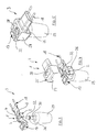
In den Figuren 1 und 2 sind schematische Darstellungen in unterschiedlichen
Ansichten einer Heizeinrichtung 1 mit einem Heizblock 2 als Bestandteil einer
hier nicht im Detail dargestellten Verdampfungsvorrichtung 3 gezeigt.In Figures 1 and 2 are schematic representations in different
Views of a
Der Heizblock 2 weist in der Draufsicht gemäß Fig. 1 eine in etwa rechteckige
Form auf, wobei in etwa in einem mittleren, zentralen Bereich des Heizblocks 2
eine Dochtaussparung 4 ausgebildet ist. Diese Dochtaussparung 4 liegt in
etwa in einem mittleren Bereich zwischen zwei als elektrische Widerstandselemente
5, 6 ausgebildeten Heizelementen.The
Diese Widerstandselemente 5, 6 sind, wie dies insbesondere aus der Fig. 2
ersichtlich ist, in einer Aussparung 7, 8 am Heizblock 2 aufgenommen und
werden dort, was hier allerdings nicht dargestellt ist, mit einem eine hohe
Wärmeleitfähigkeit aufweisenden Material, z. B. einem flammenbeständigen
Isolationszement, vergossen.These
An den gegenüberliegenden Aussparungswänden ist zu beiden Seiten der Widerstandselemente
5, 6 jeweils ein Schlitz 9, 10, 11, 12 ausgebildet, durch die
mit den Widerstandselementen 5, 6 verbundene elektrische Leitungen 13, 14,
15 und 16 herausgeführt sind. In der Fig. 7 ist ein schematischer Querschnitt
durch den Heizblock 2 entlang der Linie A-A der Fig. 1 gezeigt.On the opposite recess walls is on both sides of the
Die elektrische Leitung 13 ist vom Widerstandselement 5 ausgehend und die
elektrische Leitung 15 ist vom Widerstandselement 6 ausgehend jeweils zu
einem Handschalter 17 geführt, während die elektrische Leitung 14 des Widerstandselements
5 und die elektrische Leitung 16 des Widerstandselements 7
jeweils zu einem Anschlussstecker 18 geführt sind. Ferner ist der Handschalter
17 noch mit einer elektrischen Leitung 19 mit dem Anschlussstecker 18 verbunden.The
In der Fig. 6 ist der Aufbau der Widerstandselemente 5, 6 in vergrößerter Darstellung
gezeigt. So umfassen die Widerstandselemente 5, 6 jeweils einen
stabförmigen Widerstandskörper 20, der vorzugsweise aus Keramik hergestellt
ist mit einem bestimmten Gehalt an Al2O3 zur Einstellung guter Wärmeleiteigenschaften.
Dieser Widerstandskörper 20 ist mit einer Widerstandsschicht 21
aus Metalloxid beschichtet, wobei zur Einstellung eines bestimmten Widerstandswertes
die Widerstandsschicht 21 spiralförmig, z. B. durch Laserschneiden
eingeschnitten ist, so dass ein Spiraleinschnitt 22 um den stabförmigen,
zylindrischen Widerstandskörper 20 herum ausgebildet ist.6, the structure of the
Auf die Enden des beschichteten, stabförmigen, zylindrischen Widerstandskörpers
20 ist für eine elektrische Verbindung zu der Widerstandsschicht 21
jeweils eine Metallkappe 23, 24 aufgepresst. An diesen Kappen 23, 24 ist jeweils
eine der elektrischen Leitungen 13, 14, 15, 16, vorzugsweise ein Kupferdraht
angeschweißt, die mit einem Isolationsmaterial isoliert sind.On the ends of the coated, rod-shaped,
Wie dies weiter aus der Fig. 1 entnommen werden kann, sind die Widerstandselemente
5, 6 in etwa parallel zueinander angeordnet und weisen in
etwa einen gleichen Abstand zu der als Durchgangsloch ausgebildeten Dochtaussparung
4 auf. Die beiden Widerstandselemente 5, 6 weisen bevorzugt
unterschiedliche Widerstandswerte für unterschiedliche Heizleistungen auf.As can be seen from FIG. 1, are the
in den Figuren 3 bis 5 wird der Zusammenbau der gesamten Verdampfungsvorrichtung
3 schrittweise näher erläutert. Wie dies insbesondere den Figuren
4 und 5 entnommen werden kann, ist der Heizblock 2 im montierten Zustand in
einem Gehäuse 25 aufgenommen, wobei der Heizblock hierzu, wie dies aus
der Fig. 4 ersichtlich ist, vorzugsweise mit einer Unterschale 26 des Gehäuses
verbunden wird. In dieser Unterschale 26 ist ferner auch eine Aufnahme für
eine Integration des Handschalters 17 am Gehäuse 25 vorgesehen. Auf die
Unterschale 26 kann dann eine Oberschale 27 aufgeclipst werden, wobei
diese Oberschale einen Lüftungsschlitz 28 aufweist, über den die zu verdampfenden
Substanzen in die Umgebung entweichen können.in Figures 3 to 5 is the assembly of the
Wie dies insbesondere aus den Figuren 3 und 4 ersichtlich ist, ist in das Gehäuse
25 als weiterer Bestandteil der Verdampfungsvorrichtung 3 ein Behälter
29 einsetzbar, in den ein Docht 30 eingesetzt wird, wobei dieser Docht 30 mit
einem Dochthaltering 31 so am Behälter 29 festlegbar ist, dass der Docht 30
mit einem Dochtende 32 aus dem Behälter 29 hervorragt.As can be seen in particular from FIGS. 3 and 4, is in the
Im eingesetzten Zustand des Behälters 29 ragt dieses Dochtende 32, wie dies
aus der Fig. 4 ersichtlich ist, in die Dochtaussparung 4 des Heizblocks 2 hinein. In the inserted state of the
Mit einer derartigen Verdampfungsvorrichtung 3 sind unterschiedliche Betriebszustände
einstellbar, so z. B. ein erster Betriebszustand, bei dem durch
eine entsprechende Stellung des Handschalters 17 beide Widerstandselemente
5, 6 deaktiviert sind, so dass kein Aufheizen des Heizblocks 2 erfolgt.With such an
Für den Fall, dass das Widerstandselement 5 beispielsweise eine höhere
Heizleistung bereitstellt als das Widerstandselement 6, kann z. B. vorgesehen
werden, dass bei einer Zuschaltung lediglich des Widerstandselementes 5
eine besonders schnelle Verdampfung der im Behälter 29 aufgenommenen
und über die Kapillarwirkung des Dochtes 30 in den Bereich der Dochtaussparung
4 geförderten zu verdampfenden Substanz mit hohem Verdampfungsgrad
erfolgt. Alternativ dazu kann bei einer Zuschaltung lediglich des Widerstandselementes
6, das einen geringeren Widerstandswert aufweist, eine entsprechend
langsamere Verdampfung der im Behälter 29 aufgenommenen Substanz
erfolgen.In the event that the
Ggf. kann über den Handschalter 17 auch eine derartige Schaltung erfolgen,
dass für eine besonders schnelle und effektive Verdampfung beide Widerstandselemente
5, 6 gleichzeitig zugeschaltet sind.Possibly. such a circuit can also be carried out via the
Die Wahl der Schaltstellung bzw. die Wahl des Widerstandselements 5, 6 zum
Verdampfen kann dabei in Abhängigkeit von den eingesetzten flüchtigen Substanzen,
z. B. Insektiziden und/oder Duftstoffen erfolgen.The choice of the switching position or the choice of the
In der Fig. 8 ist eine alternative Ausführungsform eines Heizblocks 40 einer
Verdampfungsvorrichtung 41 gezeigt, bei der der Heizblock 40 zwei voneinander
beabstandete Dochtaussparungen 42, 43 aufweist, die bezogen auf die in
der Fig. 9 dargestellte Draufsicht auf den Heizblock 40 in einem mittleren Bereich
desselben zwischen zwei im randseitigen Bereich des Heizblocks angeordneten
Widerstandselementen 44, 45 (Fig. 8) angeordnet sind. In der Fig. 10
ist ein Querschnitt entlang der Linie B-B durch den Heizblock 40 der Fig. 9
dargestellt.An alternative embodiment of a
Die Widerstandselemente 44, 45 entsprechen vom Aufbau her dem Widerstandselement
3, wie es in Verbindung mit den Figuren 1 bis 7 ausführlich beschrieben
worden ist, so dass hierauf nicht mehr näher eingegangen wird.The
Die Widerstandselemente 44, 45 sind den Aussparungen 46, 47 am Heizblock
40 aufgenommen und dort einzementiert, wobei jedem Widerstandselement
44, 45 elektrische Anschlussleitungen 48, 49 sowie 50, 51 zugeordnet sind, die
durch Schlitze im Bereich der Aussparungsseitenwände herausgeführt sind
dergestalt, dass die Anschlussleitung 48 des Widerstandselements 44 sowie
die Anschlussleitung 49 des Widerstandselements 45 jeweils zu einem Handschalter
52 geführt sind. Dagegen sind die Anschlussleitung 50 des Widerstandselements
44 und die Anschlussleitung 51 des Widerstandselements 45
zu einem Anschlussstecker 53 geführt. Diese ist eine elektrische Leitung 54
vom Handschalter 52 zum Anschlussstecker 53 geführt.The
Wie dies den Figuren 8 bis 10 ferner entnommen werden kann, ist zur zumindest
teilweisen thermischen Entkopplung der beiden durch die Dochtaussparung
42 und das Widerstandselement 44 sowie die Dochtaussparung 43 und
das Widerstandselement 45 gebildeten Heizeinheiten 55 bzw. 56 in einem Bereich
zwischen den beiden Dochtaussparungen 42, 43 ein durch den Heizblock
40 durchgehender Luftspalt 57 als Trennmittel vorgesehen.As can also be seen in FIGS. 8 to 10, at least
partial thermal decoupling of the two through the
Vorzugsweise weisen die beiden Widerstandselemente 44, 45 unterschiedliche
Widerstandwerte auf.The two
Wie dies den Figuren 11 bis 13 entnommen werden kann, weist die Verdampfungsvorrichtung
41 ferner ein Behältnis 58 mit zwei Kammern 59, 60 als Behälter
auf, wobei jeder Kammer jeweils ein Docht 61, 62 zugeordnet ist, der im
montierten Zustand mit einem Dochtende 63, 64 aus den beiden Kammern 59,
60 hervorsteht. In den beiden Kammern sind vorzugsweise unterschiedliche zu
verdampfende Substanzen enthalten, die eine unterschiedliche Verdampfungstemperatur
aufweisen.As can be seen in FIGS. 11 to 13, the evaporation device has
41 also a
Im montierten Zustand ist der Heizblock 40 in einem Gehäuse 67, das wiederum
aus einer Gehäuse-Oberschale 65 und einer Gehäuse-Unterschale 66
aufgebaut ist, aufgenommen, wie dies insbesondere aus der Fig. 12 ersichtlich
ist. An diesem Gehäuse 67 kann ferner eine Aussparung zur Integration des
Handschalters 52 vorgesehen sein. Weiter umfasst die Oberschale 65 einen
Lüftungsschlitz 68.In the assembled state, the
Über den Handschalter 52 können die beiden Heizeinheiten 55, 56 einzeln aktiviert
werden, so dass entweder die in der Kammer 59 oder die in der Kammer
60 aufgenommene flüchtige Substanz verdampft wird. Die Widerstandselemente
44, 45 können dabei in ihrem Widerstandswert entsprechend an die zu
verdampfenden Substanzen in den Kammern 59, 60 angepasst sein. Der
Handschalter 52 kann zudem noch eine weitere Schaltposition aufweisen, mit
der beide Heizeinheiten 55, 56 aktiviert sind, so dass, insbesondere im Rahmen
einer Aromatherapie ein Duftstoffgemisch durch Verdampfen aus beiden
Kammern 59, 60 erzeugt werden kann. In einer weiteren Schaltposition des
Handschalters 52 sind dagegen beide Heizeinheiten 55, 56 deaktiviert. Diese
Schaltstellungen des Handschalters 52 sind hier nicht im Detail dargestellt.The two
Claims (21)
mit einem Gehäuse (25; 67)
mit einer im Gehäuse (25; 67) angeordneten Heizeinrichtung (1), die einen Heizblock (2; 40), vorzugsweise aus Keramik, umfasst, der zur Erwärmung des Heizblocks (2; 40) ein Heizelement (5; 44) aufweist,
mit einem mit dem Gehäuse (25; 67) verbindbaren Behälter (29; 59) für eine zu verdampfende Substanz, wobei in den Behälter (29; 59) ein Docht (30; 61) einsetzbar ist, der bei mit dem Gehäuse (25; 67) verbundenem Behälter (29; 59) zur Verdampfung der sich im Behälter (29; 59) befindlichen Substanz mit einem aus dem Behälter (29; 59) ragenden Dochtende (32; 63) in eine Dochtaussparung (4; 42) des Heizblocks (2; 40) ragt,
mit einer Schalteinrichtung (17; 52) zur Aktivierung und Deaktivierung der Heizeinrichtung (1), und
mit einer Einstelleinrichtung zur Einstellung des Verdampfungsgrades,
dadurch gekennzeichnet, dass am Heizblock (2; 40) wenigstens zwei Heizelemente (5, 6; 44, 45) mit unterschiedlichen Heizleistungen angeordnet sind, und
dass die wenigstens zwei Heizelemente (5, 6; 44, 45) zu deren Aktivierung und/oder Deaktivierung mit der gleichzeitig die Einstelleinrichtung bildenden Schalteinrichtung (17; 52) gekoppelt sind.Device for evaporating volatile substances, in particular insecticides and / or fragrances,
with a housing (25; 67)
with a heating device (1) arranged in the housing (25; 67), which comprises a heating block (2; 40), preferably made of ceramic, which has a heating element (5; 44) for heating the heating block (2; 40),
with a container (29; 59) for a substance to be evaporated, which can be connected to the housing (25; 67), a wick (30; 61) can be inserted into the container (29; 59), which is connected to the housing (25; 67) connected container (29; 59) for evaporating the substance in the container (29; 59) with a wick end (32; 63) protruding from the container (29; 59) into a wick recess (4; 42) of the heating block ( 2; 40) protrudes
with a switching device (17; 52) for activating and deactivating the heating device (1), and
with an adjustment device for adjusting the degree of evaporation,
characterized in that at least two heating elements (5, 6; 44, 45) with different heating powers are arranged on the heating block (2; 40), and
that the at least two heating elements (5, 6; 44, 45) for their activation and / or deactivation are coupled to the switching device (17; 52) which simultaneously forms the adjusting device.
dass die Heizelemente (5, 6; 44, 45) vorzugsweise auch gruppenweise oder gemeinsam aktivierbar sind.Device according to Claim 1, characterized in that the heating elements (5, 6; 44, 45) are coupled to the switching device (17; 52) in such a way that the heating elements (5, 6; 44, 45) can be activated individually to set the degree of evaporation or can be deactivated and deactivated together, and
that the heating elements (5, 6; 44, 45) can preferably also be activated in groups or together.
dass die Dochtaussparung (4) bezogen auf die Draufsicht in etwa in einem mittleren Bereich des Heizblocks (2) ausgebildet ist.Apparatus according to claim 3, characterized in that the heating block (2) has an approximately rectangular or approximately oval shape in a plan view,
that the wick recess (4) is formed approximately in a central region of the heating block (2) in relation to the plan view.
Heizelemente (5, 6) bezüglich der Dochtaussparung (4) aufweisen.Apparatus according to claim 3 or claim 4, characterized in that the heating elements (5, 6) are each an equal distance from the wick recess (4) for a preferably symmetrical arrangement of the
Have heating elements (5, 6) with respect to the wick recess (4).
dass jeder weiteren Dochtaussparung (43) jeweils ein weiterer Behälter (60) mit darin einsetzbarem Docht (62) so zugeordnet ist, dass ein Dochtende (64) des Dochtes (62) des weiteren Behälters (60) zur Verdampfung der sich im weiteren Behälter (60) befindlichen Substanz in die weitere Dochtaussparung (43) hineinragt.Apparatus according to claim 1 or claim 2, characterized in that at least one further wick recess (43) is provided on the heating block (40), with each wick recess (42, 43) being assigned at least one heating element (44, 45) and each wick recess ( 42, 43) and each heating element (44, 45) associated with a wick recess (42, 43) each form a heating unit (55, 56), and
that each additional wick recess (43) is assigned a further container (60) with a wick (62) that can be inserted therein so that a wick end (64) of the wick (62) of the additional container (60) for evaporation of the 60) projecting substance protrudes into the additional wick recess (43).
dass an gegenüberliegenden Aussparungswänden zu beiden Seiten des Widerstandselementes (5, 6; 44, 45) jeweils ein Schlitz (13, 14, 15, 16) ausgebildet ist, durch die die elektrischen Leitungen (13, 14, 15, 16; 48, 49, 50, 51) aus dem Heizblock (2; 40) zu einem Anschlussstecker (25; 67) bzw. zur Schalteinrichtung (17; 53) hin herausgeführt sind.Apparatus according to claim 16 or claim 17, characterized in that the rod-shaped resistance element (5, 6; 44, 45) can be introduced into a recess (7, 8; 46, 47) of the heating block (2; 40) and there with a high thermal conductivity material, preferably a flame-resistant insulating cement, is poured, and
that a slot (13, 14, 15, 16) is formed on opposite recess walls on both sides of the resistance element (5, 6; 44, 45) through which the electrical lines (13, 14, 15, 16; 48, 49 , 50, 51) are led out of the heating block (2; 40) to a connector (25; 67) or to the switching device (17; 53).
dass die Unterschale (26; 66) Verbindungsmittel zur Verbindung des Behälters (29; 59, 60) mit dem Gehäuse (25; 67) aufweist, und
dass wenigstens eine der beiden Schalen (25, 26; 65, 66), vorzugsweise die Oberschale (27; 65) im Bereich oberhalb der Dochtenden, wenigstens einen Lüftungsschlitz (28; 68) zum Entweichen der verdampften Substanzen aufweist.Device according to one of claims 1 to 20, characterized in that the housing (25; 67) is constructed at least in two parts from an upper shell (27; 65) and a lower shell (26; 66), which are preferably interconnected by latching and / or Clip elements are connectable,
that the lower shell (26; 66) has connecting means for connecting the container (29; 59, 60) to the housing (25; 67), and
that at least one of the two shells (25, 26; 65, 66), preferably the upper shell (27; 65) in the area above the wick ends, has at least one ventilation slot (28; 68) for the escape of the vaporized substances.
Priority Applications (8)
| Application Number | Priority Date | Filing Date | Title |
|---|---|---|---|
| DE50111791T DE50111791D1 (en) | 2001-04-05 | 2001-04-05 | Apparatus for evaporating volatile substances, in particular insecticides and / or fragrances |
| AT01107795T ATE349889T1 (en) | 2001-04-05 | 2001-04-05 | DEVICE FOR VAPORIZING VOLATILE SUBSTANCES, IN PARTICULAR INSECTICIDES AND/OR FRAGRANCES |
| ES01107795T ES2280280T3 (en) | 2001-04-05 | 2001-04-05 | DEVICE FOR VAPORIZATION OF VOLATILE SUBSTANCES, ESPECIALLY INSECTICIDES AND / OR AROMATIC SUBSTANCES. |
| EP01107795A EP1247446B1 (en) | 2001-04-05 | 2001-04-05 | Device for vaporising fluids, particularly insecticides and/or perfumes |
| US09/918,898 US6563091B2 (en) | 2001-04-05 | 2001-07-31 | Evaporation device for multiple volatile substances |
| US09/994,032 US6501906B2 (en) | 2000-12-18 | 2001-11-21 | Evaporation device for volatile substances |
| US11/123,252 USRE40464E1 (en) | 2001-04-05 | 2005-05-05 | Evaporation device for multiple volatile substances |
| US11/655,036 USRE44312E1 (en) | 2001-04-05 | 2007-01-18 | Evaporation device for multiple volatile substances |
Applications Claiming Priority (1)
| Application Number | Priority Date | Filing Date | Title |
|---|---|---|---|
| EP01107795A EP1247446B1 (en) | 2001-04-05 | 2001-04-05 | Device for vaporising fluids, particularly insecticides and/or perfumes |
Publications (2)
| Publication Number | Publication Date |
|---|---|
| EP1247446A1 true EP1247446A1 (en) | 2002-10-09 |
| EP1247446B1 EP1247446B1 (en) | 2007-01-03 |
Family
ID=8176979
Family Applications (1)
| Application Number | Title | Priority Date | Filing Date |
|---|---|---|---|
| EP01107795A Expired - Lifetime EP1247446B1 (en) | 2000-12-18 | 2001-04-05 | Device for vaporising fluids, particularly insecticides and/or perfumes |
Country Status (5)
| Country | Link |
|---|---|
| US (3) | US6563091B2 (en) |
| EP (1) | EP1247446B1 (en) |
| AT (1) | ATE349889T1 (en) |
| DE (1) | DE50111791D1 (en) |
| ES (1) | ES2280280T3 (en) |
Cited By (4)
| Publication number | Priority date | Publication date | Assignee | Title |
|---|---|---|---|---|
| ES2255422A1 (en) * | 2004-09-29 | 2006-06-16 | Eroski, S. Coop. | Liquid insecticide and air freshener electrical diffusor includes a heater evaporating the liquid contacted by a wick in the liquid bottle |
| US9717813B2 (en) | 2011-06-13 | 2017-08-01 | Zobele Holding Spa | Electrical heating device for evaporating volatile substances with adjustable evaporation rate |
| CN113365670A (en) * | 2018-12-14 | 2021-09-07 | 赛特奥有限公司 | Device and method for evaporating volatile substances, in particular fragrances and/or insecticides, and heating body |
| CN113797376A (en) * | 2016-12-28 | 2021-12-17 | 佐贝尔控股股份有限公司 | Device for evaporating volatile substances, comprising a core and a heat-reflecting element |
Families Citing this family (51)
| Publication number | Priority date | Publication date | Assignee | Title |
|---|---|---|---|---|
| US20040033171A1 (en) * | 2000-07-27 | 2004-02-19 | The Procter & Gamble Company | Systems and devices for emitting volatile compositions |
| US20040265164A1 (en) | 2000-07-27 | 2004-12-30 | The Procter & Gamble Company | Methods, devices, compositions, and systems for improved scent delivery |
| US8061628B1 (en) | 2000-07-27 | 2011-11-22 | The Procter & Gamble Company | Systems and devices for emitting volatile compositions |
| DE50111791D1 (en) * | 2001-04-05 | 2007-02-15 | C T R | Apparatus for evaporating volatile substances, in particular insecticides and / or fragrances |
| GB0123851D0 (en) | 2001-10-04 | 2001-11-28 | Pankhurst Design & Development | Dispersing fragrances |
| US6885811B2 (en) | 2002-08-16 | 2005-04-26 | The Dial Corporation | Methods and apparatus for dual-outlet vapor dispenser |
| US7167641B2 (en) * | 2002-06-06 | 2007-01-23 | S.C. Johnson & Son, Inc. | Localized surface volatilization |
| US20040033067A1 (en) * | 2002-08-16 | 2004-02-19 | He Mengtao Pete | Methods and apparatus for a controllable vapor-dispensing device |
| US7007863B2 (en) * | 2002-10-08 | 2006-03-07 | S.C. Johnson & Son, Inc. | Wick-based delivery system with wick made of different composite materials |
| DE60335833D1 (en) | 2002-11-08 | 2011-03-03 | Johnson & Son Inc S C | DISPENSING OF MULTIPLE VOLATILE SUBSTANCES |
| US20050089453A1 (en) * | 2003-10-24 | 2005-04-28 | Shu-Li Huang | Flame-free aromatizer burner |
| US7824627B2 (en) | 2004-02-03 | 2010-11-02 | S.C. Johnson & Son, Inc. | Active material and light emitting device |
| US7209650B2 (en) * | 2004-03-29 | 2007-04-24 | Dbk Espana, S.A. | Method and device for the evaporation of volatile compounds |
| US7389943B2 (en) * | 2004-06-30 | 2008-06-24 | S.C. Johnson & Son, Inc. | Electromechanical apparatus for dispensing volatile substances with single dispensing mechanism and cartridge for holding multiple receptacles |
| BRPI0419064A (en) * | 2004-09-14 | 2007-12-11 | Zobele Espa A S A | active component evaporator device using fan |
| ES1061683Y (en) * | 2005-11-24 | 2006-07-01 | Alonso Jose Luis Igual | ADJUSTABLE LIQUID HEATER-EVAPORATOR |
| US7493028B2 (en) * | 2006-04-04 | 2009-02-17 | Group Dekko, Inc. | Multiple bottle evaporative diffuser |
| US8320751B2 (en) | 2007-12-20 | 2012-11-27 | S.C. Johnson & Son, Inc. | Volatile material diffuser and method of preventing undesirable mixing of volatile materials |
| US8550091B2 (en) * | 2008-11-24 | 2013-10-08 | Kannel Management, Llc | Electrically heated water pipe smoking device |
| USD651088S1 (en) | 2009-12-14 | 2011-12-27 | Kristian Buschmann | Bottle |
| USD650681S1 (en) | 2009-12-14 | 2011-12-20 | Kristian Buschmann | Bottle |
| USD650684S1 (en) | 2009-12-14 | 2011-12-20 | Kristian Buschmann | Bottle |
| USD650682S1 (en) | 2009-12-14 | 2011-12-20 | Kristian Buschmann | Bottle |
| USD650683S1 (en) | 2009-12-14 | 2011-12-20 | Kristian Buschmann | Bottle |
| USD646573S1 (en) | 2009-12-14 | 2011-10-11 | Kubicek Chris A | Bottle |
| US20110139891A1 (en) * | 2009-12-15 | 2011-06-16 | Gasper Thomas P | Refill, attachment for a refill, and method of retaining a refill |
| USD639923S1 (en) | 2010-04-15 | 2011-06-14 | S.C. Johnson & Son, Inc. | Dispensing device |
| USD732389S1 (en) | 2012-07-31 | 2015-06-23 | S.C. Johnson & Son, Inc. | Cap |
| US8983279B2 (en) | 2012-07-31 | 2015-03-17 | S.C. Johnson & Son, Inc. | Volatile material dispenser and method of emitting a volatile material |
| US9669126B2 (en) | 2012-08-06 | 2017-06-06 | S.C. Johnson & Son, Inc. | Volatile material dispenser and method of emitting a volatile material |
| US11134544B2 (en) | 2015-07-24 | 2021-09-28 | Rai Strategic Holdings, Inc. | Aerosol delivery device with radiant heating |
| US10206429B2 (en) * | 2015-07-24 | 2019-02-19 | Rai Strategic Holdings, Inc. | Aerosol delivery device with radiant heating |
| USD809116S1 (en) | 2015-11-02 | 2018-01-30 | Pura Scents | Dispenser |
| CA3133710C (en) * | 2015-11-02 | 2023-10-24 | Pura Scents, Inc. | Scent dispensation |
| USD816506S1 (en) | 2015-11-02 | 2018-05-01 | Pura Scents, Inc. | Vial for a scent dispenser |
| US9855361B2 (en) | 2015-12-14 | 2018-01-02 | S. C. Johnson & Son, Inc. | Compositions, delivery systems and refills for emitting two or more compositions |
| US10433580B2 (en) | 2016-03-03 | 2019-10-08 | Altria Client Services Llc | Methods to add menthol, botanic materials, and/or non-botanic materials to a cartridge, and/or an electronic vaping device including the cartridge |
| US10455863B2 (en) | 2016-03-03 | 2019-10-29 | Altria Client Services Llc | Cartridge for electronic vaping device |
| US10368580B2 (en) * | 2016-03-08 | 2019-08-06 | Altria Client Services Llc | Combined cartridge for electronic vaping device |
| US10368581B2 (en) | 2016-03-11 | 2019-08-06 | Altria Client Services Llc | Multiple dispersion generator e-vaping device |
| US10357060B2 (en) | 2016-03-11 | 2019-07-23 | Altria Client Services Llc | E-vaping device cartridge holder |
| EP3471784A1 (en) | 2016-06-16 | 2019-04-24 | CTR, Lda | Wick device for evaporating fragrance having a flow channel |
| WO2017215728A1 (en) | 2016-06-16 | 2017-12-21 | Ctr, Lda | Device for dispensing, in particular for vaporizing, volatile substances, in particular fragrances and/or active agents |
| US10405580B2 (en) * | 2016-07-07 | 2019-09-10 | Altria Client Services Llc | Mechanically-adjustable e-vaping device flavor assembly |
| US10764963B2 (en) | 2016-10-07 | 2020-09-01 | S. C. Johnson & Son, Inc. | Volatile material dispenser |
| US10512250B2 (en) * | 2017-05-03 | 2019-12-24 | Edik A. Puzankov | Oxalic acid vaporizer with integral body tube, detachable proximal end air nozzle, and floating heating element |
| USD846724S1 (en) | 2017-10-23 | 2019-04-23 | S. C. Johnson & Son, Inc. | Dispenser |
| USD859163S1 (en) | 2017-10-23 | 2019-09-10 | S. C. Johnson & Son, Inc. | Container with cover |
| USD846725S1 (en) | 2017-10-23 | 2019-04-23 | S. C. Johnson & Son, Inc. | Dispenser |
| USD871226S1 (en) | 2017-10-23 | 2019-12-31 | S. C. Johnson & Son, Inc. | Container |
| CN216533460U (en) * | 2021-12-24 | 2022-05-17 | 深圳维冠通实业有限公司 | Mosquito dispeller for dual purposes of mosquito-repellent incense tablet and mosquito-repellent incense liquid |
Citations (9)
| Publication number | Priority date | Publication date | Assignee | Title |
|---|---|---|---|---|
| EP0689766A1 (en) * | 1994-06-28 | 1996-01-03 | FALP S.r.l. | Apparatus for vaporizing insecticidal solutions and the like |
| JPH08155018A (en) * | 1994-12-09 | 1996-06-18 | Casio Comput Co Ltd | Evapotranspiration device |
| JPH0910292A (en) * | 1995-06-29 | 1997-01-14 | Casio Comput Co Ltd | Transpiration device |
| WO1998058692A1 (en) | 1997-06-24 | 1998-12-30 | Dbk España S.A. | Evaporator device of volatile products with variable evaporation intensity |
| EP0911041A2 (en) * | 1997-10-27 | 1999-04-28 | FALP S.r.l. | Device for electrically vaporizing active principles |
| EP0943344A1 (en) | 1998-03-19 | 1999-09-22 | ZOBELE INDUSTRIE CHIMICHE S.p.A. | Vaporizer for a liquid insecticide or perfume composition, with regulation of the intensity of the heat flow |
| EP0962132A1 (en) | 1998-06-05 | 1999-12-08 | ZOBELE INDUSTRIE CHIMICHE S.p.A. | Electric evaporator for insecticides or perfumes in liquid formulations with device to adjust the evaporation intensity |
| EP1055430A1 (en) * | 1999-05-27 | 2000-11-29 | FALP S.r.l. | Electric vaporizer, particularly for deodorant and insecticidal liquids and the like |
| WO2001005442A1 (en) * | 1999-07-17 | 2001-01-25 | Reckitt Benckiser (Uk) Limited | Fragrance emitting device |
Family Cites Families (43)
| Publication number | Priority date | Publication date | Assignee | Title |
|---|---|---|---|---|
| US2715056A (en) * | 1955-08-09 | Wilson | ||
| US1154113A (en) | 1913-10-23 | 1915-09-21 | William S Hadaway Jr | Humidifier. |
| US1346793A (en) * | 1916-03-27 | 1920-07-13 | Quincy A Gates | Electric heater |
| US3028100A (en) | 1958-11-26 | 1962-04-03 | Airkem Inc | Wick support means for non-spillable wick bottles |
| US3440589A (en) | 1966-04-01 | 1969-04-22 | Brunswick Corp | Resistor unit and method of making same |
| US3414864A (en) * | 1967-06-08 | 1968-12-03 | Irc Inc | Electrical resistor |
| US3633881A (en) | 1969-10-09 | 1972-01-11 | Alfred Yurdin | Evaporative deodorizing system |
| US3672568A (en) | 1970-08-12 | 1972-06-27 | Foote Allen | Humidifier |
| JPS58135183A (en) | 1982-02-08 | 1983-08-11 | 株式会社デンソー | Metallized ceramic resistor |
| US4498071A (en) | 1982-09-30 | 1985-02-05 | Dale Electronics, Inc. | High resistance film resistor |
| US4629604A (en) | 1983-03-21 | 1986-12-16 | Donald Spector | Multi-aroma cartridge player |
| FR2571259B1 (en) | 1984-10-09 | 1987-02-20 | Reckitt Colman | VOLATILE LIQUID DIFFUSER |
| US4659905A (en) * | 1985-09-26 | 1987-04-21 | Kenneth Gabrosek | Electric blanket |
| US4739928A (en) | 1985-10-15 | 1988-04-26 | The Drackett Company | Air freshener dispenser |
| US4742960A (en) | 1986-05-01 | 1988-05-10 | O'connor Products Company, Inc. | Wick dispenser |
| JPS6439745A (en) | 1987-08-06 | 1989-02-10 | Fuji Electric Co Ltd | Manufacture of semiconductor substrate for integrated circuit device |
| JPH0718294Y2 (en) | 1988-02-10 | 1995-05-01 | アース製薬株式会社 | Heating evaporator |
| US5427278A (en) | 1988-09-09 | 1995-06-27 | Gardner, Iii; William G. | Highlighting-ink remover applicator |
| JPH03147731A (en) | 1989-11-06 | 1991-06-24 | Fumakilla Ltd | Thermal transpiratory unit |
| DE4011629A1 (en) | 1990-04-11 | 1991-10-17 | Globol Gmbh | Electric material vaporisation device e.g. for perfume |
| US5175791A (en) * | 1990-05-07 | 1992-12-29 | Technical Concepts, L.P. | Fragrance diffuser having stepped power levels |
| US5264681A (en) | 1991-02-14 | 1993-11-23 | Ngk Spark Plug Co., Ltd. | Ceramic heater |
| DE4292013B8 (en) | 1991-06-26 | 2005-06-30 | Tdk Corp. | Device with a PTC resistor and a heater |
| US5222186A (en) * | 1991-12-06 | 1993-06-22 | Globol Gmbh | Electrical apparatus for vaporizing of active substances |
| GB2279010A (en) | 1993-06-18 | 1994-12-21 | Kuan Hua Pu | A Device for selectively generating perfume gas |
| DE9314747U1 (en) * | 1993-09-30 | 1994-02-10 | Rowenta Werke Gmbh | Electrical circuit arrangement for the flicker standard-compliant and network feedback-free heating power control of heating resistors of electrical household appliances, in particular electrical bread toasters |
| US5647053A (en) | 1995-10-11 | 1997-07-08 | S. C. Johnson & Son, Inc. | Vapor dipensing device |
| JP3088277B2 (en) | 1995-10-25 | 2000-09-18 | オカモト産業株式会社 | Air freshener container |
| IT1287235B1 (en) | 1996-04-19 | 1998-08-04 | Michelin Lausarot Elisa | MULTIPLE ELECTRO-EMANATOR FOR RESINS |
| IT240993Y1 (en) | 1996-11-07 | 2001-04-20 | Zobele Ind Chim | OVEN FOR EVAPORATION WITH ADJUSTABLE INTENSITY OF CHEMICALS |
| JPH11391A (en) | 1997-06-13 | 1999-01-06 | Matsushita Electric Ind Co Ltd | Aromatic vessel |
| KR100502203B1 (en) | 1997-06-18 | 2005-07-22 | 디비케이 에스파냐 쏘시에떼아노님 | New electric heating device with emission of active substances |
| US6172343B1 (en) * | 1998-03-09 | 2001-01-09 | Marley Electric Heating | Heater and heater control with selective power rating |
| US6078728A (en) | 1998-06-22 | 2000-06-20 | S. C. Johnson & Son, Inc. | Volatile carrier for use with a heating device |
| US6361752B1 (en) * | 1999-05-19 | 2002-03-26 | S. C. Johnson & Son, Inc. | Apparatus for volatilizing and dispensing a chemical into a room environment |
| ATE263485T1 (en) | 1999-12-18 | 2004-04-15 | C T R Consultoria Tecnica E Re | DEVICE FOR VAPORIZING VOLATILE SUBSTANCES, IN PARTICULAR INSECTICIDES AND/OR FRAGRANCES |
| US6236807B1 (en) | 2000-01-07 | 2001-05-22 | Bath & Body Works, Inc. | Wick-based liquid emanation system with child-resistant and miniaturization features |
| FR2804662B1 (en) | 2000-02-04 | 2002-05-03 | Qualipac Sa | DEVICE FOR FIXING ON A BOTTLE NECK, ASSEMBLY AND MACHINE FOR FIXING THE DEVICE |
| IT1318278B1 (en) | 2000-07-28 | 2003-07-28 | Zobele Ind Chimiche S P A Ora | ELECTRIC VAPORIZER OF INSECTICIDES OR PERFUMES IN LIQUID FORMULATIONS, WITH ADJUSTABLE EVAPORATION INTENSITY. |
| US6501906B2 (en) | 2000-12-18 | 2002-12-31 | C.T.R. Consultoria Tecnica E Representacoes Lda | Evaporation device for volatile substances |
| ATE275821T1 (en) | 2001-04-05 | 2004-10-15 | C T R Consultoria Tecnica E Re | DEVICE FOR VAPORIZING VOLATILE SUBSTANCES, IN PARTICULAR INSECTICIDES AND/OR FRAGRANCES |
| DE50111791D1 (en) * | 2001-04-05 | 2007-02-15 | C T R | Apparatus for evaporating volatile substances, in particular insecticides and / or fragrances |
| US6896196B2 (en) | 2002-01-16 | 2005-05-24 | C.T.R. Consultoria Tecnica E Representacoes Lda | Evaporative container for volatile substances |
-
2001
- 2001-04-05 DE DE50111791T patent/DE50111791D1/en not_active Expired - Lifetime
- 2001-04-05 ES ES01107795T patent/ES2280280T3/en not_active Expired - Lifetime
- 2001-04-05 AT AT01107795T patent/ATE349889T1/en not_active IP Right Cessation
- 2001-04-05 EP EP01107795A patent/EP1247446B1/en not_active Expired - Lifetime
- 2001-07-31 US US09/918,898 patent/US6563091B2/en not_active Ceased
-
2005
- 2005-05-05 US US11/123,252 patent/USRE40464E1/en not_active Expired - Lifetime
-
2007
- 2007-01-18 US US11/655,036 patent/USRE44312E1/en not_active Expired - Lifetime
Patent Citations (9)
| Publication number | Priority date | Publication date | Assignee | Title |
|---|---|---|---|---|
| EP0689766A1 (en) * | 1994-06-28 | 1996-01-03 | FALP S.r.l. | Apparatus for vaporizing insecticidal solutions and the like |
| JPH08155018A (en) * | 1994-12-09 | 1996-06-18 | Casio Comput Co Ltd | Evapotranspiration device |
| JPH0910292A (en) * | 1995-06-29 | 1997-01-14 | Casio Comput Co Ltd | Transpiration device |
| WO1998058692A1 (en) | 1997-06-24 | 1998-12-30 | Dbk España S.A. | Evaporator device of volatile products with variable evaporation intensity |
| EP0911041A2 (en) * | 1997-10-27 | 1999-04-28 | FALP S.r.l. | Device for electrically vaporizing active principles |
| EP0943344A1 (en) | 1998-03-19 | 1999-09-22 | ZOBELE INDUSTRIE CHIMICHE S.p.A. | Vaporizer for a liquid insecticide or perfume composition, with regulation of the intensity of the heat flow |
| EP0962132A1 (en) | 1998-06-05 | 1999-12-08 | ZOBELE INDUSTRIE CHIMICHE S.p.A. | Electric evaporator for insecticides or perfumes in liquid formulations with device to adjust the evaporation intensity |
| EP1055430A1 (en) * | 1999-05-27 | 2000-11-29 | FALP S.r.l. | Electric vaporizer, particularly for deodorant and insecticidal liquids and the like |
| WO2001005442A1 (en) * | 1999-07-17 | 2001-01-25 | Reckitt Benckiser (Uk) Limited | Fragrance emitting device |
Non-Patent Citations (2)
| Title |
|---|
| PATENT ABSTRACTS OF JAPAN vol. 1996, no. 10 31 October 1996 (1996-10-31) * |
| PATENT ABSTRACTS OF JAPAN vol. 1997, no. 05 30 May 1997 (1997-05-30) * |
Cited By (6)
| Publication number | Priority date | Publication date | Assignee | Title |
|---|---|---|---|---|
| ES2255422A1 (en) * | 2004-09-29 | 2006-06-16 | Eroski, S. Coop. | Liquid insecticide and air freshener electrical diffusor includes a heater evaporating the liquid contacted by a wick in the liquid bottle |
| US9717813B2 (en) | 2011-06-13 | 2017-08-01 | Zobele Holding Spa | Electrical heating device for evaporating volatile substances with adjustable evaporation rate |
| CN113797376A (en) * | 2016-12-28 | 2021-12-17 | 佐贝尔控股股份有限公司 | Device for evaporating volatile substances, comprising a core and a heat-reflecting element |
| CN113797376B (en) * | 2016-12-28 | 2024-03-22 | 佐贝尔控股股份有限公司 | Device for evaporating volatile substances, comprising a core and a heat-reflecting element |
| CN113365670A (en) * | 2018-12-14 | 2021-09-07 | 赛特奥有限公司 | Device and method for evaporating volatile substances, in particular fragrances and/or insecticides, and heating body |
| CN113365670B (en) * | 2018-12-14 | 2023-07-07 | 赛特奥有限公司 | Device and method for evaporating volatile substances, in particular fragrances and/or insecticides, and heating body |
Also Published As
| Publication number | Publication date |
|---|---|
| ATE349889T1 (en) | 2007-01-15 |
| USRE40464E1 (en) | 2008-08-26 |
| DE50111791D1 (en) | 2007-02-15 |
| US20020144992A1 (en) | 2002-10-10 |
| ES2280280T3 (en) | 2007-09-16 |
| USRE44312E1 (en) | 2013-06-25 |
| US6563091B2 (en) | 2003-05-13 |
| EP1247446B1 (en) | 2007-01-03 |
Similar Documents
| Publication | Publication Date | Title |
|---|---|---|
| EP1247447B1 (en) | Device for vaporising fluids, particularly insecticides and/or perfumes | |
| EP1247446A1 (en) | Device for vaporising fluids, particularly insecticides and/or perfumes | |
| DE602005000088T2 (en) | ELECTRIC EVAPORATOR WITH WICK-ADAPTATION THROUGH A DIRECTORY | |
| DE102007047415B3 (en) | A liquid vaporizer | |
| DE60107504T2 (en) | Electric vaporizer for insecticides or perfumes in liquid formulation with vapor intensity control device | |
| EP3192333B1 (en) | Electrode arrangement for forming a dielectric barrier plasma discharge | |
| DE60200606T2 (en) | Thermal evaporator, container for the thermal evaporator and thermal evaporator unit | |
| DE102016106283A1 (en) | smoking device | |
| CH714564A2 (en) | Liquid reservoir comprising a porous sintered body and evaporator for hot applications. | |
| EP1108358A1 (en) | Device for vaporizing volatile substances, in particular insecticides and/or perfumes | |
| EP3694349B1 (en) | Inhaler, particularly electronic cigarette product | |
| DE2320573A1 (en) | DEVICE FOR EVAPORATING SUBSTANCES | |
| DE69906542T2 (en) | MULTI-PURPOSE HEATING DEVICE FOR EVAPORATING ACTIVE SUBSTANCES | |
| EP1472761A1 (en) | Remakeable connector arrangement | |
| EP0451331B1 (en) | Electrical device for evaporating substances of efficacy | |
| EP2011521B1 (en) | Sulphur vaporiser | |
| DE60202818T2 (en) | Heater for electric diffuser | |
| EP0209832A2 (en) | Push button operated excess current protective circuit breaker | |
| EP1195169B1 (en) | Vaporisation device for volatile compounds, in particular for insecticides or perfumes | |
| DE8502409U1 (en) | Device for vaporizing active substances stored in cellulose or other carrier materials, such as pyrethrum | |
| DE3701499A1 (en) | Device for evaporating insecticides, fragrances and/or other volatile active substances | |
| EP1516633A1 (en) | Apparatus for evaporating volatile compounds, in particular perfumes and/or insecticides, heating device, and method for preparing a heating device | |
| DE60307791T2 (en) | EXPANSION UNIT | |
| DE2726608C2 (en) | Pressure-dependent electrical switching device | |
| DE10305069A1 (en) | Electrical resistance for use in protective switching device, especially power circuit breaker, consists of band of electrically conductive material wound with insulating layer between windings |
Legal Events
| Date | Code | Title | Description |
|---|---|---|---|
| PUAI | Public reference made under article 153(3) epc to a published international application that has entered the european phase |
Free format text: ORIGINAL CODE: 0009012 |
|
| AK | Designated contracting states |
Kind code of ref document: A1 Designated state(s): AT BE CH CY DE DK ES FI FR GB GR IE IT LI LU MC NL PT SE TR |
|
| AX | Request for extension of the european patent |
Free format text: AL;LT;LV;MK;RO;SI |
|
| 17P | Request for examination filed |
Effective date: 20021001 |
|
| AKX | Designation fees paid |
Designated state(s): AT BE CH CY DE DK ES FI FR GB GR IE IT LI LU MC NL PT SE TR |
|
| 17Q | First examination report despatched |
Effective date: 20040706 |
|
| GRAP | Despatch of communication of intention to grant a patent |
Free format text: ORIGINAL CODE: EPIDOSNIGR1 |
|
| GRAS | Grant fee paid |
Free format text: ORIGINAL CODE: EPIDOSNIGR3 |
|
| GRAA | (expected) grant |
Free format text: ORIGINAL CODE: 0009210 |
|
| AK | Designated contracting states |
Kind code of ref document: B1 Designated state(s): AT BE CH CY DE DK ES FI FR GB GR IE IT LI LU MC NL PT SE TR |
|
| PG25 | Lapsed in a contracting state [announced via postgrant information from national office to epo] |
Ref country code: IE Free format text: LAPSE BECAUSE OF FAILURE TO SUBMIT A TRANSLATION OF THE DESCRIPTION OR TO PAY THE FEE WITHIN THE PRESCRIBED TIME-LIMIT Effective date: 20070103 Ref country code: NL Free format text: LAPSE BECAUSE OF FAILURE TO SUBMIT A TRANSLATION OF THE DESCRIPTION OR TO PAY THE FEE WITHIN THE PRESCRIBED TIME-LIMIT Effective date: 20070103 Ref country code: FI Free format text: LAPSE BECAUSE OF FAILURE TO SUBMIT A TRANSLATION OF THE DESCRIPTION OR TO PAY THE FEE WITHIN THE PRESCRIBED TIME-LIMIT Effective date: 20070103 Ref country code: DK Free format text: LAPSE BECAUSE OF FAILURE TO SUBMIT A TRANSLATION OF THE DESCRIPTION OR TO PAY THE FEE WITHIN THE PRESCRIBED TIME-LIMIT Effective date: 20070103 |
|
| REG | Reference to a national code |
Ref country code: GB Ref legal event code: FG4D Free format text: NOT ENGLISH |
|
| REF | Corresponds to: |
Ref document number: 50111791 Country of ref document: DE Date of ref document: 20070215 Kind code of ref document: P |
|
| REG | Reference to a national code |
Ref country code: IE Ref legal event code: FG4D Free format text: LANGUAGE OF EP DOCUMENT: GERMAN |
|
| PG25 | Lapsed in a contracting state [announced via postgrant information from national office to epo] |
Ref country code: SE Free format text: LAPSE BECAUSE OF FAILURE TO SUBMIT A TRANSLATION OF THE DESCRIPTION OR TO PAY THE FEE WITHIN THE PRESCRIBED TIME-LIMIT Effective date: 20070403 |
|
| GBT | Gb: translation of ep patent filed (gb section 77(6)(a)/1977) |
Effective date: 20070404 |
|
| PG25 | Lapsed in a contracting state [announced via postgrant information from national office to epo] |
Ref country code: PT Free format text: LAPSE BECAUSE OF FAILURE TO SUBMIT A TRANSLATION OF THE DESCRIPTION OR TO PAY THE FEE WITHIN THE PRESCRIBED TIME-LIMIT Effective date: 20070604 |
|
| NLV1 | Nl: lapsed or annulled due to failure to fulfill the requirements of art. 29p and 29m of the patents act | ||
| ET | Fr: translation filed | ||
| REG | Reference to a national code |
Ref country code: IE Ref legal event code: FD4D |
|
| REG | Reference to a national code |
Ref country code: ES Ref legal event code: FG2A Ref document number: 2280280 Country of ref document: ES Kind code of ref document: T3 |
|
| PLBE | No opposition filed within time limit |
Free format text: ORIGINAL CODE: 0009261 |
|
| STAA | Information on the status of an ep patent application or granted ep patent |
Free format text: STATUS: NO OPPOSITION FILED WITHIN TIME LIMIT |
|
| 26N | No opposition filed |
Effective date: 20071005 |
|
| REG | Reference to a national code |
Ref country code: CH Ref legal event code: PL |
|
| BERE | Be: lapsed |
Owner name: C.T.R., CONSULTORIA, TECNICA E REPRESENTACOES LDA Effective date: 20070430 |
|
| PG25 | Lapsed in a contracting state [announced via postgrant information from national office to epo] |
Ref country code: CH Free format text: LAPSE BECAUSE OF NON-PAYMENT OF DUE FEES Effective date: 20070430 Ref country code: LI Free format text: LAPSE BECAUSE OF NON-PAYMENT OF DUE FEES Effective date: 20070430 |
|
| PG25 | Lapsed in a contracting state [announced via postgrant information from national office to epo] |
Ref country code: BE Free format text: LAPSE BECAUSE OF NON-PAYMENT OF DUE FEES Effective date: 20070430 |
|
| PG25 | Lapsed in a contracting state [announced via postgrant information from national office to epo] |
Ref country code: GR Free format text: LAPSE BECAUSE OF FAILURE TO SUBMIT A TRANSLATION OF THE DESCRIPTION OR TO PAY THE FEE WITHIN THE PRESCRIBED TIME-LIMIT Effective date: 20070404 |
|
| PG25 | Lapsed in a contracting state [announced via postgrant information from national office to epo] |
Ref country code: AT Free format text: LAPSE BECAUSE OF NON-PAYMENT OF DUE FEES Effective date: 20070405 |
|
| PG25 | Lapsed in a contracting state [announced via postgrant information from national office to epo] |
Ref country code: MC Free format text: LAPSE BECAUSE OF NON-PAYMENT OF DUE FEES Effective date: 20070430 |
|
| PG25 | Lapsed in a contracting state [announced via postgrant information from national office to epo] |
Ref country code: CY Free format text: LAPSE BECAUSE OF FAILURE TO SUBMIT A TRANSLATION OF THE DESCRIPTION OR TO PAY THE FEE WITHIN THE PRESCRIBED TIME-LIMIT Effective date: 20070103 |
|
| PG25 | Lapsed in a contracting state [announced via postgrant information from national office to epo] |
Ref country code: LU Free format text: LAPSE BECAUSE OF NON-PAYMENT OF DUE FEES Effective date: 20070405 |
|
| PG25 | Lapsed in a contracting state [announced via postgrant information from national office to epo] |
Ref country code: TR Free format text: LAPSE BECAUSE OF FAILURE TO SUBMIT A TRANSLATION OF THE DESCRIPTION OR TO PAY THE FEE WITHIN THE PRESCRIBED TIME-LIMIT Effective date: 20070103 |
|
| REG | Reference to a national code |
Ref country code: FR Ref legal event code: PLFP Year of fee payment: 16 |
|
| REG | Reference to a national code |
Ref country code: FR Ref legal event code: PLFP Year of fee payment: 17 |
|
| REG | Reference to a national code |
Ref country code: FR Ref legal event code: PLFP Year of fee payment: 18 |
|
| PGFP | Annual fee paid to national office [announced via postgrant information from national office to epo] |
Ref country code: ES Payment date: 20200504 Year of fee payment: 20 Ref country code: FR Payment date: 20200429 Year of fee payment: 20 Ref country code: DE Payment date: 20200529 Year of fee payment: 20 |
|
| PGFP | Annual fee paid to national office [announced via postgrant information from national office to epo] |
Ref country code: IT Payment date: 20200429 Year of fee payment: 20 Ref country code: GB Payment date: 20200408 Year of fee payment: 20 |
|
| REG | Reference to a national code |
Ref country code: DE Ref legal event code: R071 Ref document number: 50111791 Country of ref document: DE |
|
| REG | Reference to a national code |
Ref country code: GB Ref legal event code: PE20 Expiry date: 20210404 |
|
| PG25 | Lapsed in a contracting state [announced via postgrant information from national office to epo] |
Ref country code: GB Free format text: LAPSE BECAUSE OF EXPIRATION OF PROTECTION Effective date: 20210404 |
|
| REG | Reference to a national code |
Ref country code: ES Ref legal event code: FD2A Effective date: 20220128 |
|
| PG25 | Lapsed in a contracting state [announced via postgrant information from national office to epo] |
Ref country code: ES Free format text: LAPSE BECAUSE OF EXPIRATION OF PROTECTION Effective date: 20210406 |