EP1246352A2 - Wechselrichterstromversorgungsgerät - Google Patents
Wechselrichterstromversorgungsgerät Download PDFInfo
- Publication number
- EP1246352A2 EP1246352A2 EP02003976A EP02003976A EP1246352A2 EP 1246352 A2 EP1246352 A2 EP 1246352A2 EP 02003976 A EP02003976 A EP 02003976A EP 02003976 A EP02003976 A EP 02003976A EP 1246352 A2 EP1246352 A2 EP 1246352A2
- Authority
- EP
- European Patent Office
- Prior art keywords
- voltage
- power supply
- switches
- supply apparatus
- semiconductor switches
- Prior art date
- Legal status (The legal status is an assumption and is not a legal conclusion. Google has not performed a legal analysis and makes no representation as to the accuracy of the status listed.)
- Granted
Links
Images

Classifications
-
- H—ELECTRICITY
- H02—GENERATION; CONVERSION OR DISTRIBUTION OF ELECTRIC POWER
- H02M—APPARATUS FOR CONVERSION BETWEEN AC AND AC, BETWEEN AC AND DC, OR BETWEEN DC AND DC, AND FOR USE WITH MAINS OR SIMILAR POWER SUPPLY SYSTEMS; CONVERSION OF DC OR AC INPUT POWER INTO SURGE OUTPUT POWER; CONTROL OR REGULATION THEREOF
- H02M3/00—Conversion of DC power input into DC power output
- H02M3/22—Conversion of DC power input into DC power output with intermediate conversion into AC
- H02M3/24—Conversion of DC power input into DC power output with intermediate conversion into AC by static converters
- H02M3/28—Conversion of DC power input into DC power output with intermediate conversion into AC by static converters using discharge tubes with control electrode or semiconductor devices with control electrode to produce the intermediate AC
- H02M3/325—Conversion of DC power input into DC power output with intermediate conversion into AC by static converters using discharge tubes with control electrode or semiconductor devices with control electrode to produce the intermediate AC using devices of a triode or a transistor type requiring continuous application of a control signal
- H02M3/335—Conversion of DC power input into DC power output with intermediate conversion into AC by static converters using discharge tubes with control electrode or semiconductor devices with control electrode to produce the intermediate AC using devices of a triode or a transistor type requiring continuous application of a control signal using semiconductor devices only
- H02M3/33569—Conversion of DC power input into DC power output with intermediate conversion into AC by static converters using discharge tubes with control electrode or semiconductor devices with control electrode to produce the intermediate AC using devices of a triode or a transistor type requiring continuous application of a control signal using semiconductor devices only having several active switching elements
- H02M3/33573—Full-bridge at primary side of an isolation transformer
Definitions
- the present invention relates to an inverter-type power supply apparatus operating at high frequencies, comprising two series-connected input stages, which are connected to a single isolating transformer, and an electronic driving and control circuit.
- the invention relates to an apparatus for supplying power by static conversion of energy of the above described type, adapted to supply high-power users, with a regulated and/or stabilized output, by drawing energy from high-voltage DC supplies, typically but not exclusively up to 4000 V.
- Power supply systems of this type are generally constituted by H-type bridges, which use multiple semiconductor switches connected in series in the individual bridge branches.
- a circuit solution which employs multiple H-type bridges (in a configuration with four semiconductor switches, or with two semiconductor switches plus two switching capacitors) connected in series, each provided with its own isolating transformer, which is required in order to allow correct organization of the connections of the outputs so as to achieve performance at nominal power, and other accessories, such as filters and individual control systems.
- converters are used in two cascade-connected stages, each constituted by two switches and two diodes, with a common point at the central point of the supply voltage.
- a power supply apparatus comprising an inverter circuit with two series-connected stages, complete with control and monitoring device, characterized in that:
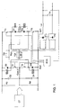
- FIG 1 illustrates the basic architecture of the apparatus according to the invention.
- the conductors of the input line, designated by LI, supply by means of an upstream filter not shown in the figure, the positive and negative bars of the two-stage inverter.
- Each stage comprises two semiconductor switches l1, l2 - l3, l4 and two recirculation diodes D1, D2 - D3, D4.
- the two capacitors C2 and C4 are connected in parallel to the string Str 2 of two switches and two diodes, characterized in that the two switches l2 and l4 have a common point; the capacitors are in turn connected in series and their central point is connected to the central point of the string of switches and diodes Com 2: therefore, more accurately, to the common point of the two switches.
- the central point Com 1 of the string Str 1 of two switches and two diodes is connected to the central point of the string Str 2 of two switches and two diodes - and therefore also to the central point of the series of two capacitors cited above - across a coupling capacitor C2, with a corresponding discharge resistor Rsc.
- the corresponding snubbers Sn1 ⁇ Sn4 are connected in parallel to the four diodes D1 ⁇ D4.
- One of the two primary windings of the isolating transformer is connected in the common points between each semiconductor switch and the corresponding recirculation diode, which individually belongs to each one of the two stages.
- a winding of the current transducer TDI is connected in series to each primary winding, and monitors the current in the two primary windings of the transformer.
- the signal provided by the transducer is processed by the control logic of the inverter, which corrects the duration of the power-on sequences of the semiconductor switches, in order to ensure the best balancing of the conduction steps of the two stages that constitute the power supply apparatus and avoid the formation of a continuous component in the primary winding of the main transformer.
- Two secondary windings supply two single-phase bridges (P1, P2), which supply power to the users by means of a filter Lu, Cu.
- the users can be classic static converters (suitable for DC to AC conversion or for DC to DC conversion), which in turn supply the loads, or can be directly constituted by the final loads.
- An electronic driving and control system manages the correct operation of the power supply apparatus.
- the connections of the two stages that constitute the power supply apparatus can be carried to a terminal strip having no more than 9 terminals, which constitutes a voltage changer (CT).
- CT voltage changer
- the machine can be preset to be series-connected or parallel-connected and to receive the full input voltage or half of it, by means of the connection of the terminals in three sets only.
- the nominal power can be delivered by the machine, in both cases, with an equal stress affecting the components of the converter.
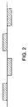
- Figure 2 shows the output voltage at the transformer, which in the specific case is obtained with a particular adjustment technique known as phase shifting, which is adapted to control the delivered voltage and/or current according to the requirements of the users.
- phase shifting a particular adjustment technique known as phase shifting, which is adapted to control the delivered voltage and/or current according to the requirements of the users.
- the switch-on angle of l2, l4 with respect to l1, l3 varies, the voltage applied to the main transformer varies and the output voltage is thus adjusted.
- Other adjustment methods can be used likewise.
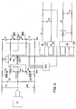
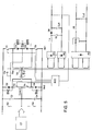
- Figure 3 illustrates an apparatus according to a further aspect of the invention, and further comprising two tertiary low voltage windings, a corresponding rectifier bridge P3, a regulator REG, and an output filter Lb, Cb.
- the power supply apparatus shown in the embodiment of Figure 3 can be used, typically but not exclusively, for charging one or more batteries which are usually present in the more characteristic applications of power supply apparatus such as the one to which the present invention relates.
- This second output of the power supply apparatus is completed by a system for detecting the delivery parameters and by its own regulation system (REG), generally of the switching type, which are designed to correctly manage the voltage and current values supplied to the battery and to the corresponding users.
- REG own regulation system
- the apparatus further comprises a solid-state switch T5 / D5, acting as a step-up converter, which is driven, when active, by the control logic synchronously with the solid-state switches T1 ⁇ T4.
- this apparatus allows to optimize the sizing of the four solid-state switches of the converter with respect to switching losses. These losses constitute the largest fraction of all operating losses of these semiconductors in the classic applications of this type of machine.
Landscapes
- Engineering & Computer Science (AREA)
- Power Engineering (AREA)
- Dc-Dc Converters (AREA)
- Inverter Devices (AREA)
- Dry Shavers And Clippers (AREA)
- Heat-Pump Type And Storage Water Heaters (AREA)
- Prostheses (AREA)
Applications Claiming Priority (2)
| Application Number | Priority Date | Filing Date | Title |
|---|---|---|---|
| IT2001GE000016A ITGE20010016A1 (it) | 2001-02-23 | 2001-02-23 | Sistema di alimentazione comprendente un convertitore a ponte semidoppio. |
| ITGE010016 | 2001-02-23 |
Publications (3)
| Publication Number | Publication Date |
|---|---|
| EP1246352A2 true EP1246352A2 (de) | 2002-10-02 |
| EP1246352A3 EP1246352A3 (de) | 2004-06-30 |
| EP1246352B1 EP1246352B1 (de) | 2009-06-24 |
Family
ID=11442734
Family Applications (1)
| Application Number | Title | Priority Date | Filing Date |
|---|---|---|---|
| EP02003976A Expired - Lifetime EP1246352B1 (de) | 2001-02-23 | 2002-02-22 | Wechselrichterstromversorgungsgerät |
Country Status (5)
| Country | Link |
|---|---|
| EP (1) | EP1246352B1 (de) |
| AT (1) | ATE434857T1 (de) |
| DE (1) | DE60232698D1 (de) |
| ES (1) | ES2328672T3 (de) |
| IT (1) | ITGE20010016A1 (de) |
Family Cites Families (5)
| Publication number | Priority date | Publication date | Assignee | Title |
|---|---|---|---|---|
| US4754385A (en) * | 1987-01-30 | 1988-06-28 | Varo, Inc. | Two transistor flyback switching converter with current sensing for discontinuous operation |
| US5180964A (en) * | 1990-03-28 | 1993-01-19 | Ewing Gerald D | Zero-voltage switched FM-PWM converter |
| SE467384B (sv) * | 1990-10-24 | 1992-07-06 | Ericsson Telefon Ab L M | Saett och kopplingsanordning foer att vid omriktare balansera ingaangs- och/eller utgaangsspaenningsavvikelser |
| US5781419A (en) * | 1996-04-12 | 1998-07-14 | Soft Switching Technologies, Inc. | Soft switching DC-to-DC converter with coupled inductors |
| IT1290082B1 (it) * | 1997-03-14 | 1998-10-19 | Italtel Spa | Convertitore dc/dc di elevata potenza |
-
2001
- 2001-02-23 IT IT2001GE000016A patent/ITGE20010016A1/it unknown
-
2002
- 2002-02-22 EP EP02003976A patent/EP1246352B1/de not_active Expired - Lifetime
- 2002-02-22 DE DE60232698T patent/DE60232698D1/de not_active Expired - Lifetime
- 2002-02-22 ES ES02003976T patent/ES2328672T3/es not_active Expired - Lifetime
- 2002-02-22 AT AT02003976T patent/ATE434857T1/de not_active IP Right Cessation
Also Published As
| Publication number | Publication date |
|---|---|
| EP1246352A3 (de) | 2004-06-30 |
| ITGE20010016A1 (it) | 2002-08-23 |
| ATE434857T1 (de) | 2009-07-15 |
| DE60232698D1 (de) | 2009-08-06 |
| EP1246352B1 (de) | 2009-06-24 |
| ES2328672T3 (es) | 2009-11-17 |
Similar Documents
| Publication | Publication Date | Title |
|---|---|---|
| US8138694B2 (en) | Bidirectional buck-boost power converters | |
| US7456524B2 (en) | Apparatus for and methods of polyphase power conversion | |
| EP3455934B1 (de) | Regelung einer transformator-gleichrichter-einheit für hochleistungsanwendungen | |
| JP5425193B2 (ja) | 電力入力を備えた回路構成及び電力入力回路を制御する動作方法 | |
| AU2007202910B2 (en) | Power supply for electrostatic precipitator | |
| US9479011B2 (en) | Method and system for a dual conversion uninterruptible power supply | |
| US12362592B2 (en) | Power factor correction circuit, power factor correction assembly and on-line uninterruptible power supply comprising same | |
| US7151680B2 (en) | Switching power supply circuit and frequency converter | |
| US20170310111A1 (en) | High voltage dc power supply for high power radio frequency amplifiers | |
| KR101768256B1 (ko) | 듀얼 구조의 파워 셀을 구비하는 인버터 | |
| US20230352930A1 (en) | Dc power distribution system | |
| EP1246352B1 (de) | Wechselrichterstromversorgungsgerät | |
| WO2021001888A1 (ja) | 電力変換装置 | |
| KR101343953B1 (ko) | 배터리 방전기를 제거한 이중변환 무정전전원장치 | |
| US10158284B2 (en) | PFC with stacked half-bridges on DC side of rectifier | |
| US20260031744A1 (en) | Power Converter With Auxiliary Voltage Supply | |
| KR100490645B1 (ko) | 비절연형 무정전 전원공급 장치 | |
| US20250192553A1 (en) | Solid-state power controller with transformer soft-start | |
| JPH04275022A (ja) | 直流電力供給システムの起動方法 | |
| Séguier et al. | Introduction and Presentation |
Legal Events
| Date | Code | Title | Description |
|---|---|---|---|
| PUAI | Public reference made under article 153(3) epc to a published international application that has entered the european phase |
Free format text: ORIGINAL CODE: 0009012 |
|
| AK | Designated contracting states |
Kind code of ref document: A2 Designated state(s): AT BE CH CY DE DK ES FI FR GB GR IE IT LI LU MC NL PT SE TR |
|
| AX | Request for extension of the european patent |
Free format text: AL;LT;LV;MK;RO;SI |
|
| PUAL | Search report despatched |
Free format text: ORIGINAL CODE: 0009013 |
|
| AK | Designated contracting states |
Kind code of ref document: A3 Designated state(s): AT BE CH CY DE DK ES FI FR GB GR IE IT LI LU MC NL PT SE TR |
|
| AX | Request for extension of the european patent |
Extension state: AL LT LV MK RO SI |
|
| 17P | Request for examination filed |
Effective date: 20041116 |
|
| AKX | Designation fees paid |
Designated state(s): AT BE CH CY DE DK ES FI FR GB GR IE IT LI LU MC NL PT SE TR |
|
| RAP1 | Party data changed (applicant data changed or rights of an application transferred) |
Owner name: R.G.M. S.P.A. |
|
| GRAP | Despatch of communication of intention to grant a patent |
Free format text: ORIGINAL CODE: EPIDOSNIGR1 |
|
| GRAS | Grant fee paid |
Free format text: ORIGINAL CODE: EPIDOSNIGR3 |
|
| GRAA | (expected) grant |
Free format text: ORIGINAL CODE: 0009210 |
|
| AK | Designated contracting states |
Kind code of ref document: B1 Designated state(s): AT BE CH CY DE DK ES FI FR GB GR IE IT LI LU MC NL PT SE TR |
|
| REG | Reference to a national code |
Ref country code: GB Ref legal event code: FG4D |
|
| REG | Reference to a national code |
Ref country code: CH Ref legal event code: EP |
|
| REG | Reference to a national code |
Ref country code: IE Ref legal event code: FG4D |
|
| REF | Corresponds to: |
Ref document number: 60232698 Country of ref document: DE Date of ref document: 20090806 Kind code of ref document: P |
|
| PG25 | Lapsed in a contracting state [announced via postgrant information from national office to epo] |
Ref country code: AT Free format text: LAPSE BECAUSE OF FAILURE TO SUBMIT A TRANSLATION OF THE DESCRIPTION OR TO PAY THE FEE WITHIN THE PRESCRIBED TIME-LIMIT Effective date: 20090624 Ref country code: FI Free format text: LAPSE BECAUSE OF FAILURE TO SUBMIT A TRANSLATION OF THE DESCRIPTION OR TO PAY THE FEE WITHIN THE PRESCRIBED TIME-LIMIT Effective date: 20090624 |
|
| REG | Reference to a national code |
Ref country code: ES Ref legal event code: FG2A Ref document number: 2328672 Country of ref document: ES Kind code of ref document: T3 |
|
| PG25 | Lapsed in a contracting state [announced via postgrant information from national office to epo] |
Ref country code: SE Free format text: LAPSE BECAUSE OF FAILURE TO SUBMIT A TRANSLATION OF THE DESCRIPTION OR TO PAY THE FEE WITHIN THE PRESCRIBED TIME-LIMIT Effective date: 20090924 |
|
| NLV1 | Nl: lapsed or annulled due to failure to fulfill the requirements of art. 29p and 29m of the patents act | ||
| PG25 | Lapsed in a contracting state [announced via postgrant information from national office to epo] |
Ref country code: NL Free format text: LAPSE BECAUSE OF FAILURE TO SUBMIT A TRANSLATION OF THE DESCRIPTION OR TO PAY THE FEE WITHIN THE PRESCRIBED TIME-LIMIT Effective date: 20090624 Ref country code: BE Free format text: LAPSE BECAUSE OF FAILURE TO SUBMIT A TRANSLATION OF THE DESCRIPTION OR TO PAY THE FEE WITHIN THE PRESCRIBED TIME-LIMIT Effective date: 20090624 |
|
| PG25 | Lapsed in a contracting state [announced via postgrant information from national office to epo] |
Ref country code: PT Free format text: LAPSE BECAUSE OF FAILURE TO SUBMIT A TRANSLATION OF THE DESCRIPTION OR TO PAY THE FEE WITHIN THE PRESCRIBED TIME-LIMIT Effective date: 20091024 |
|
| PG25 | Lapsed in a contracting state [announced via postgrant information from national office to epo] |
Ref country code: DK Free format text: LAPSE BECAUSE OF FAILURE TO SUBMIT A TRANSLATION OF THE DESCRIPTION OR TO PAY THE FEE WITHIN THE PRESCRIBED TIME-LIMIT Effective date: 20090624 |
|
| PLBE | No opposition filed within time limit |
Free format text: ORIGINAL CODE: 0009261 |
|
| STAA | Information on the status of an ep patent application or granted ep patent |
Free format text: STATUS: NO OPPOSITION FILED WITHIN TIME LIMIT |
|
| 26N | No opposition filed |
Effective date: 20100325 |
|
| REG | Reference to a national code |
Ref country code: CH Ref legal event code: PL |
|
| GBPC | Gb: european patent ceased through non-payment of renewal fee |
Effective date: 20100222 |
|
| PG25 | Lapsed in a contracting state [announced via postgrant information from national office to epo] |
Ref country code: GR Free format text: LAPSE BECAUSE OF FAILURE TO SUBMIT A TRANSLATION OF THE DESCRIPTION OR TO PAY THE FEE WITHIN THE PRESCRIBED TIME-LIMIT Effective date: 20090925 Ref country code: LI Free format text: LAPSE BECAUSE OF NON-PAYMENT OF DUE FEES Effective date: 20100228 Ref country code: MC Free format text: LAPSE BECAUSE OF NON-PAYMENT OF DUE FEES Effective date: 20100301 Ref country code: CH Free format text: LAPSE BECAUSE OF NON-PAYMENT OF DUE FEES Effective date: 20100228 |
|
| PG25 | Lapsed in a contracting state [announced via postgrant information from national office to epo] |
Ref country code: IE Free format text: LAPSE BECAUSE OF NON-PAYMENT OF DUE FEES Effective date: 20100222 |
|
| PG25 | Lapsed in a contracting state [announced via postgrant information from national office to epo] |
Ref country code: GB Free format text: LAPSE BECAUSE OF NON-PAYMENT OF DUE FEES Effective date: 20100222 |
|
| PG25 | Lapsed in a contracting state [announced via postgrant information from national office to epo] |
Ref country code: CY Free format text: LAPSE BECAUSE OF FAILURE TO SUBMIT A TRANSLATION OF THE DESCRIPTION OR TO PAY THE FEE WITHIN THE PRESCRIBED TIME-LIMIT Effective date: 20090624 |
|
| PG25 | Lapsed in a contracting state [announced via postgrant information from national office to epo] |
Ref country code: LU Free format text: LAPSE BECAUSE OF NON-PAYMENT OF DUE FEES Effective date: 20100222 |
|
| PG25 | Lapsed in a contracting state [announced via postgrant information from national office to epo] |
Ref country code: TR Free format text: LAPSE BECAUSE OF FAILURE TO SUBMIT A TRANSLATION OF THE DESCRIPTION OR TO PAY THE FEE WITHIN THE PRESCRIBED TIME-LIMIT Effective date: 20090624 |
|
| REG | Reference to a national code |
Ref country code: FR Ref legal event code: PLFP Year of fee payment: 15 |
|
| REG | Reference to a national code |
Ref country code: FR Ref legal event code: PLFP Year of fee payment: 16 |
|
| REG | Reference to a national code |
Ref country code: FR Ref legal event code: PLFP Year of fee payment: 17 |
|
| REG | Reference to a national code |
Ref country code: DE Ref legal event code: R082 Ref document number: 60232698 Country of ref document: DE Representative=s name: MAUCHER JENKINS PATENTANWAELTE & RECHTSANWAELT, DE Ref country code: DE Ref legal event code: R081 Ref document number: 60232698 Country of ref document: DE Owner name: ABB SCHWEIZ AG, CH Free format text: FORMER OWNER: R.G.M. S.P.A., GENUA/GENOVA, IT |
|
| REG | Reference to a national code |
Ref country code: ES Ref legal event code: PC2A Owner name: ABB SCHWEIZ AG Effective date: 20200605 |
|
| PGFP | Annual fee paid to national office [announced via postgrant information from national office to epo] |
Ref country code: FR Payment date: 20210224 Year of fee payment: 20 Ref country code: IT Payment date: 20210222 Year of fee payment: 20 |
|
| PGFP | Annual fee paid to national office [announced via postgrant information from national office to epo] |
Ref country code: DE Payment date: 20210217 Year of fee payment: 20 |
|
| PGFP | Annual fee paid to national office [announced via postgrant information from national office to epo] |
Ref country code: ES Payment date: 20210421 Year of fee payment: 20 |
|
| REG | Reference to a national code |
Ref country code: DE Ref legal event code: R071 Ref document number: 60232698 Country of ref document: DE |
|
| PG25 | Lapsed in a contracting state [announced via postgrant information from national office to epo] |
Ref country code: ES Free format text: LAPSE BECAUSE OF EXPIRATION OF PROTECTION Effective date: 20220223 |