EP1245966A1 - Verfahren und Vorrichtung zur Detektion von Objekten in Entfernungszellen mittels Radarsignalen - Google Patents
Verfahren und Vorrichtung zur Detektion von Objekten in Entfernungszellen mittels Radarsignalen Download PDFInfo
- Publication number
- EP1245966A1 EP1245966A1 EP02004446A EP02004446A EP1245966A1 EP 1245966 A1 EP1245966 A1 EP 1245966A1 EP 02004446 A EP02004446 A EP 02004446A EP 02004446 A EP02004446 A EP 02004446A EP 1245966 A1 EP1245966 A1 EP 1245966A1
- Authority
- EP
- European Patent Office
- Prior art keywords
- objects
- distance
- cells
- signals
- filter
- Prior art date
- Legal status (The legal status is an assumption and is not a legal conclusion. Google has not performed a legal analysis and makes no representation as to the accuracy of the status listed.)
- Granted
Links
- 238000000034 method Methods 0.000 title claims abstract description 24
- 238000001514 detection method Methods 0.000 title claims description 21
- 238000004590 computer program Methods 0.000 claims abstract description 14
- 238000001914 filtration Methods 0.000 claims abstract description 12
- 238000011156 evaluation Methods 0.000 claims abstract description 8
- 238000012546 transfer Methods 0.000 claims description 24
- 230000000630 rising effect Effects 0.000 claims description 5
- 230000001629 suppression Effects 0.000 claims description 5
- 230000007423 decrease Effects 0.000 claims description 4
- 238000005070 sampling Methods 0.000 description 10
- 230000002238 attenuated effect Effects 0.000 description 5
- 238000011161 development Methods 0.000 description 3
- 238000013016 damping Methods 0.000 description 2
- 230000035484 reaction time Effects 0.000 description 2
- 230000005540 biological transmission Effects 0.000 description 1
- 230000015572 biosynthetic process Effects 0.000 description 1
- 230000000903 blocking effect Effects 0.000 description 1
- 230000003247 decreasing effect Effects 0.000 description 1
- 230000008030 elimination Effects 0.000 description 1
- 238000003379 elimination reaction Methods 0.000 description 1
- 238000005516 engineering process Methods 0.000 description 1
- 238000009472 formulation Methods 0.000 description 1
- 230000001788 irregular Effects 0.000 description 1
- 238000012423 maintenance Methods 0.000 description 1
- 239000000203 mixture Substances 0.000 description 1
- 230000000737 periodic effect Effects 0.000 description 1
- 238000001228 spectrum Methods 0.000 description 1
Images


Classifications
-
- G—PHYSICS
- G01—MEASURING; TESTING
- G01S—RADIO DIRECTION-FINDING; RADIO NAVIGATION; DETERMINING DISTANCE OR VELOCITY BY USE OF RADIO WAVES; LOCATING OR PRESENCE-DETECTING BY USE OF THE REFLECTION OR RERADIATION OF RADIO WAVES; ANALOGOUS ARRANGEMENTS USING OTHER WAVES
- G01S13/00—Systems using the reflection or reradiation of radio waves, e.g. radar systems; Analogous systems using reflection or reradiation of waves whose nature or wavelength is irrelevant or unspecified
- G01S13/02—Systems using reflection of radio waves, e.g. primary radar systems; Analogous systems
- G01S13/50—Systems of measurement based on relative movement of target
- G01S13/52—Discriminating between fixed and moving objects or between objects moving at different speeds
- G01S13/522—Discriminating between fixed and moving objects or between objects moving at different speeds using transmissions of interrupted pulse modulated waves
- G01S13/524—Discriminating between fixed and moving objects or between objects moving at different speeds using transmissions of interrupted pulse modulated waves based upon the phase or frequency shift resulting from movement of objects, with reference to the transmitted signals, e.g. coherent MTi
- G01S13/526—Discriminating between fixed and moving objects or between objects moving at different speeds using transmissions of interrupted pulse modulated waves based upon the phase or frequency shift resulting from movement of objects, with reference to the transmitted signals, e.g. coherent MTi performing filtering on the whole spectrum without loss of range information, e.g. using delay line cancellers or comb filters
Definitions
- the present invention relates to a method and a Device for the detection of objects in range cells by scanning the distance cells by means of pulsed Radar signals.
- the radar signals are directed towards the Range cells sent out and at least from the objects partially reflected.
- the reflected radar signals are received and evaluated.
- the received signals become suppression as part of the evaluation fixed objects are filtered.
- the invention also relates to a digital filter for Use in such a device.
- the digital Filter filters the received radar signals Suppression of objects with a relative speed from zero.
- the present invention also relates to a Storage element on which a computer program is stored is that on a computing device, in particular on a Microprocessor or on a digital signal processor (DSP), is executable.
- a Storage element on which a computer program is stored is that on a computing device, in particular on a Microprocessor or on a digital signal processor (DSP), is executable.
- DSP digital signal processor
- the present invention also relates to a Computer program running on a computing device, in particular on a microprocessor or on a digital one Signal processor (DSP), is executable.
- a Computer program running on a computing device, in particular on a microprocessor or on a digital one Signal processor (DSP), is executable.
- DSP digital one Signal processor
- ETS pulse radar devices become Detection of objects in distance cells, for example as Parking aid used in a motor vehicle. there the range cells using radar signals sampled. An ETS radar device sends radar signals in Towards the range cells. At least part of the radar signals are emitted on the objects in the Range cells reflected. The reflected Radar signals are received by the ETS pulse radar device and evaluated. With an ETS pulse radar device you can use the transit time of the radar signals from their emission to Reception of signals reflected from an object Distance to the object can be determined.
- ETS pulse radar devices become Detection of objects in distance cells, for example as Parking aid used in a motor vehicle. there the range cells using radar signals sampled. An ETS radar device sends radar signals in Towards the range cells. At least part of the radar signals are emitted on the objects in the Range cells reflected. The reflected Radar signals are received by the ETS pulse radar device and evaluated. With an ETS pulse radar device you can use the transit time of the radar signals from their emission to Reception of signals
- An ETS pulse radar device controls an internal variable Dead time element over time and thereby transfers the Runtime of possible reflected signals in one equivalent timeline.
- This principle is already in one German patent application DE 199 19 227 the same Applicant has been described in detail. To this Registration is expressly referred to.
- a stationary object is, for example, a wavy one or irregular road surface on which emitted Radar signals reflected and as interference signals from the ETS pulse radar device be received. These interference signals are eliminated or strongly attenuated by the filtering.
- Filtering is, for example, according to the prior art digital moving target indication (MTI) filter used.
- MTI digital moving target indication
- the MTI filter detects signals from an object to be reflected, which deals with a Relative speed below a predefinable one Minimum speed moves eliminated or damped.
- Objects with Doppler frequencies below a predefinable minimum frequency corresponding to the minimum speed are damped by the MTI filter. This means that an object must exceed the minimum speed in order to reach the passband of the MTI filter.
- the present invention is therefore based on the object based on the reliability of the detection of objects in to increase the range cells.
- the invention suggests of the method for detection of objects in Range cells by scanning the range cells by means of radar signals of the type mentioned in the introduction that the received signals with digital filtering subject to variable dead times.
- the reactive frequencies of the digital filter can according to the invention in ranges of the Doppler frequency or in Areas of relative speed of an object be moved for the detection of the object are uninteresting or less important.
- the reactive frequency can be selected by choosing an appropriate filter dead time T Relative speed to be shifted with that most likely will not move an object.
- T Relative speed to be shifted with that most likely will not move an object.
- the reactive frequency can, for example, also lead to a Relative speed to be shifted at one a detection of itself that has not occurred Relative speed moving object no or hardly Has an impact on detection reliability. This is For example, the case at relative speeds that are so low are that the collision time is the maximum response time exceeds, or are so large that the Collision time falls below the minimum response time.
- the reactive frequencies of the digital filter depending on the distance detected objects is varied.
- the other consideration is the minimum response time the driver. Objects that are about the distance have increasing radial relative speed a collision time that is the response time of the Driver falls below and thus inevitably to Collision with the vehicle.
- the digital filter should now be designed so that the first blind speed over the distance the Response time of the driver is less than possible (i.e. V_blind> s_object / T_reaction_min).
- the reactive frequencies with increasing distance of the detected objects increasing to get voted.
- the reactive frequencies with increasing distance of the detected objects to Reaching a predeterminable distance value increases and again after a predeterminable dead time has passed descending.
- the reactive frequencies are advantageously trapezoidal chosen increasing and decreasing. If the Range cells are trapezoidally shaped, results between the samples of the increasing and the descending trapezoidal flank over the same distance cell a dead time that decreases proportionally with the distance.
- the present invention proposes that at several sequentially consecutive each rising and falling corner frequencies the respective dead times can be chosen differently and the Transfer functions of the corresponding filters through a Function for determining the maximum value of the Transfer functions are superimposed.
- a digital filter can be used for the transmission functions a resulting transfer function is modeled that do not exist in the area of the blind speeds or only a slight attenuation of the received signals causes.
- numerator and denominator of the ratio prime numbers or Are multiples of prime numbers are multiples of prime numbers.
- the respective dead times selected such that in a Series of immediately consecutive prime numbers between the prime number corresponding to the longest dead time and the the prime number corresponding to the next lower dead time there is at least one other prime number. In this way can attenuate the received signals in the range of Blind speeds on average to a very small one Value can be reduced.
- the invention also relates to a Computer program that is used to execute the invention Is suitable if it is on a computing device, especially on a microprocessor. Especially it is preferred if the computer program on a Storage element is stored.
- ETS pulse radars are used to detect objects in range cells used for example as a parking aid in a motor vehicle. The range cells are measured using radar signals sampled. An ETS radar device sends radar signals in Towards the range cells. At least part of the radar signals are emitted on the objects in the Range cells reflected. The reflected Radar signals are received by the ETS pulse radar device and evaluated. With an ETS pulse radar device you can use the transit time of the radar signals from their emission to Reception of signals reflected from an object Distance to the object can be determined.
- An ETS pulse radar device controls an internal variable Dead time element over time and thereby transfers the Runtime of possible reflected signals in one equivalent timeline.
- This principle is already in one German patent application DE 199 19 227 the same Applicant has been described in detail. To this Registration is expressly referred to.
- a fixed object is, for example Road surface at which radar signals are emitted reflected and as interference signals from the ETS pulse radar device be received. These interference signals are caused by the Filtering eliminated or heavily damped.
- MTI digital moving target according to the prior art Indication (MTI) filter used. Through the MTI filter signals that are reflected by an object that is at a speed below one specifiable minimum speed moves eliminated or attenuated.
- Objects with Doppler frequencies below a predefinable minimum frequency corresponding to the minimum speed are damped by the MTI filter. This means that an object must exceed the minimum speed in order to reach the passband of the MTI filter.
- MTI filters are usually implemented in software by linking sequentially obtained data.
- the data are usually read in at a fixed sampling rate 1 / T.
- 2 *
- a chain of several MTI levels corresponds to a corresponding potentiation of the transfer function. This is largely determined by the sampling time T.
- FIG. 2 A transfer function of an MTI filter known from the prior art is shown in FIG. 2.
- f_carrier 24 GHz
- a radially moving object generates a Doppler frequency f_doppler proportional to the radial speed.
- the speed V_object of the object is represented by the frequency f_doppler in FIG. 2 as a dashed line.
- the filter curve shows that objects with Doppler frequencies f_doppler maintenance 3.33 Hz are attenuated with at least 6 dB.
- the corner frequencies can be in the range of the Doppler frequency f_doppler or in areas of relative speed V_object of an object to be moved for the Detection of the object uninteresting or less important are.
- a transfer function of an inventive Filters is shown in Figure 1. It is clearly too recognize that the filter is not fixed but rather has variable corner frequencies.
- the other consideration is the minimum response time the driver. Objects that are about the distance have increasing radial relative speed a collision time that is the response time of the Driver falls below and thus inevitably to Collision with the vehicle.
- the maximal Blind speed (solid line) and the minimum Blind speed (dashed line) of an object are shown in Figure 3.
- Figure 4 is the maximum Doppler frequency (solid line) and the minimum Doppler frequency (dashed line) of an object shown.
- the digital filter according to the invention is designed such that the first blind speed over the distance the Response time of the driver is less than possible.
- the corner frequencies shown in FIG. 4 are shown in Converted filter dead times.
- the minimum frequency dashed line
- the first reactive frequency solid line
- the first Blind frequency of the upper 6 dB corner frequency of the lowest Bandpass of the periodic MTI filter spectrum consequently a maximum dead time not by the MTI filter should be exceeded.
- FIG. 5 shows a trapezoid with which the Range cells according to a preferred embodiment of the present invention. Between Samples of the rising and falling Sweep edges result from the same distance cell a dead time that decreases proportionally with the distance. For a distance cell at 5m there is, for example Dead time of 3ms and one for a distance cell at 10m Dead time of 0.5 ms.
- a further embodiment of the present Invention is proposed sequentially in several successive sweep traces the respective dead times to choose differently and then the maximum value of Transfer functions of the corresponding filters determine.
- the evaluation of several sequentially consecutive sweeptrapeze is thus together linked by a binary OR.
- three trapezoids are provided, which have different trapezoidal hold times, e.g. 0.5ms; 0.75ms and 1.75ms.
- the keystone times are in a ratio of 7: 3 or 7: 2 to each other, where 2, 3 and 7 are prime numbers.
- immediately successive prime numbers (1, 2, 3, 5, 7, 11, ...) lies between that corresponding to the longest dead time Prime number 7 and that of the next lower dead time corresponding prime number 3 at least one further prime number, namely 5. It has been shown that with such selected trapezoid holding times particularly good results let achieve.
Landscapes
- Engineering & Computer Science (AREA)
- Radar, Positioning & Navigation (AREA)
- Remote Sensing (AREA)
- Computer Networks & Wireless Communication (AREA)
- Physics & Mathematics (AREA)
- General Physics & Mathematics (AREA)
- Radar Systems Or Details Thereof (AREA)
Abstract
Description
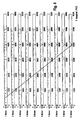
- Figur 1
- eine Übertragungsfunktion eines erfindungsgemäßen digitalen Filters;
- Figur 2
- eine Übertragungsfunktion eines aus dem Stand der Technik bekannten digitalen Filters;
- Figur 3
- minimale und maximale Blindgeschwindigkeiten eines Objekts in Abhängigkeit von der Entfernung zu dem Objekt;
- Figur 4
- minimale und maximale Eckfrequenzen eines erfindungsgemäßen digitalen Filters in Abhängigkeit von der Entfernung zu einem Objekt;
- Figur 5
- ein Sweepsignal zur Abtastung einer Entfernungszelle; und
- Figur 6
- Übertragungsfunktionen eines erfindungsgemäßen digitalen Filters für verschiedene Entfernungen zu einem Objekt.

Claims (14)
- Verfahren zur Detektion von Objekten in Entfernungszellen durch Abtastung der Entfernungszellen mittels gepulster Radarsignale, die in Richtung der Entfernungszellen ausgesandt, von den Objekten zumindest teilweise reflektiert, empfangen und ausgewertet werden, wobei die empfangenen Signale im Rahmen der Auswertung zur Unterdrückung feststehender Objekte einer Filterung unterzogen werden, dadurch gekennzeichnet, dass die empfangenen Signale einer digitalen Filterung mit variablen Totzeiten unterzogen werden.
- Verfahren nach Anspruch 1, dadurch gekennzeichnet, dass Blindfrequenzen der digitalen Filterung in Abhängigkeit von der Entfernung detektierter Objekte variiert werden.
- Verfahren nach Anspruch 2, dadurch gekennzeichnet, dass die Blindfrequenzen mit zunehmender Entfernung der detektierten Objekte ansteigend gewählt werden.
- Verfahren nach Anspruch 2, dadurch gekennzeichnet, dass die Blindfrequenzen mit zunehmender Entfernung der detektierten Objekte bis zum Erreichen eines vorgebbaren Entfernungswertes ansteigend und nach dem Verstreichen einer vorgebbaren Totzeit wieder abfallend gewählt werden.
- Verfahren nach Anspruch 4, dadurch gekennzeichnet, dass die Blindfrequenzen trapezförmig ansteigend und abfallend gewählt werden.
- Verfahren nach Anspruch 4 oder 5, dadurch gekennzeichnet, dass bei mehreren sequenziell aufeinanderfolgenden jeweils ansteigenden und wieder abfallenden Blindfrequenzen die jeweiligen Totzeiten unterschiedlich gewählt werden und die Übertragungsfunktionen der entsprechenden Filter durch eine Funktion zur Ermittlung des Maximalwerts der Übertragungsfunktionen überlagert werden.
- Verfahren nach Anspruch 6, dadurch gekennzeichnet, dass bei drei sequenziell aufeinanderfolgenden jeweils ansteigenden und wieder abfallenden Blindfrequenzen die jeweiligen Totzeiten unterschiedlich gewählt werden und die Übertragungsfunktionen der entsprechenden Filter durch eine Funktion zur Ermittlung des Maximalwerts der Übertragungsfunktionen überlagert werden.
- Verfahren nach Anspruch 6 oder 7, dadurch gekennzeichnet, dass die jeweiligen Totzeiten in einem derartigen Verhältnis zueinander gewählt werden, dass Zähler und Nenner des Verhältnisses Primzahlen oder Vielfache von Primzahlen sind.
- Verfahren nach Anspruch 8, dadurch gekennzeichnet, dass die jeweiligen Totzeiten derart gewählt werden, dass in einer Reihe unmittelbar aufeinanderfolgender Primzahlen zwischen der der längsten Totzeit entsprechenden Primzahl und der der nächst niedrigeren Totzeit entsprechenden Primzahl mindestens eine weitere Primzahl liegt.
- Vorrichtung zur Detektion von Objekten in Entfernungszellen durch Abtastung der Entfernungszellen mittels Radarsignalen, die in Richtung der Entfernungszellen ausgesandt, von den Objekten zumindest teilweise reflektiert, empfangen und ausgewertet werden, wobei die Vorrichtung ein digitales Filter zur Filterung der empfangenen Signale im Rahmen der Auswertung zur Unterdrückung feststehender Objekte aufweist, dadurch gekennzeichnet, dass die Vorrichtung Mittel zur Ausführung eines Verfahrens nach einem der Ansprüche 1 bis 9 aufweist.
- Digitales Filter zum Einsatz in einer Vorrichtung zur Detektion von Objekten in Entfernungszellen durch Abtastung der Entfernungszellen mittels Radarsignalen, die in Richtung der Entfernungszellen ausgesandt, von den Objekten zumindest teilweise reflektiert, empfangen und ausgewertet werden, wobei das digitale Filter die empfangenen Signale im Rahmen der Auswertung zur Unterdrückung feststehender Objekte filtert, dadurch gekennzeichnet, dass das Filter Mittel zur Ausführung eines Verfahrens nach einem der Ansprüche 1 bis 9 aufweist.
- Speicherelement, auf dem ein Computerprogramm abgespeichert ist, das auf einem Rechengerät, insbesondere auf einem Mikroprozessor oder auf einem digitalen Signalprozessor (DSP), ablauffähig und zur Ausführung eines Verfahrens nach einem der Ansprüche 1 bis 9 geeignet ist.
- Computerprogramm, dadurch gekennzeichnet, dass das Computerprogramm zur Ausführung eines Verfahrens nach einem der Ansprüche 1 bis 9 geeignet ist, wenn es auf einem Rechengerät, insbesondere auf einem Mikroprozessor oder auf einem digitalen Signalprozessor (DSP), abläuft.
- Computerprogramm nach Anspruch 13, dadurch gekennzeichnet, dass das Computerprogramm auf einem Speicherelement abgespeichert ist.
Applications Claiming Priority (2)
| Application Number | Priority Date | Filing Date | Title |
|---|---|---|---|
| DE10115607 | 2001-03-29 | ||
| DE2001115607 DE10115607A1 (de) | 2001-03-29 | 2001-03-29 | Verfahren und Vorrichtung zur Detektion von Objekten in Entfernungszellen mittels Radarsignalen |
Publications (2)
| Publication Number | Publication Date |
|---|---|
| EP1245966A1 true EP1245966A1 (de) | 2002-10-02 |
| EP1245966B1 EP1245966B1 (de) | 2011-02-16 |
Family
ID=7679577
Family Applications (1)
| Application Number | Title | Priority Date | Filing Date |
|---|---|---|---|
| EP20020004446 Expired - Lifetime EP1245966B1 (de) | 2001-03-29 | 2002-02-27 | Verfahren und Vorrichtung zur Detektion von Objekten in Entfernungszellen mittels Radarsignalen |
Country Status (2)
| Country | Link |
|---|---|
| EP (1) | EP1245966B1 (de) |
| DE (2) | DE10115607A1 (de) |
Cited By (1)
| Publication number | Priority date | Publication date | Assignee | Title |
|---|---|---|---|---|
| RU2393499C2 (ru) * | 2007-08-24 | 2010-06-27 | Анатолий Борисович Атнашев | Способ определения скорости движения и дальности объекта |
Citations (4)
| Publication number | Priority date | Publication date | Assignee | Title |
|---|---|---|---|---|
| EP0031752A2 (de) * | 1979-12-28 | 1981-07-08 | Thomson-Csf | Testechounterdrückungsvorrichtung in elektronischen Detektionsvorrichtungen und mit Digitalfilter versehene Detektionsausrüstung mit einer solchen Vorrichtung |
| FR2550347A1 (fr) * | 1975-10-29 | 1985-02-08 | Labo Cent Telecommunicat | Perfectionnements aux radars doppler a impulsions |
| US4965584A (en) * | 1988-03-18 | 1990-10-23 | Thomson Csf | Method and devices for translation along the axis of frequencies of the modulus of the transfer function of a filter |
| EP1048960A2 (de) * | 1999-04-28 | 2000-11-02 | Valeo Schalter und Sensoren GmbH | Flexible Ansteuerung für KFZ-Nahbereichs-Pulsradar |
Family Cites Families (4)
| Publication number | Priority date | Publication date | Assignee | Title |
|---|---|---|---|---|
| US3742500A (en) * | 1970-08-24 | 1973-06-26 | Raytheon Co | Mti radar |
| US4011438A (en) * | 1975-12-17 | 1977-03-08 | Motorola, Inc. | Simplified digital moving target indicator filter |
| US4394658A (en) * | 1981-03-27 | 1983-07-19 | Sperry Corporation | Adaptive MTI clutter tracker-canceller method and apparatus |
| US5990824A (en) * | 1998-06-19 | 1999-11-23 | Northrop Grumman Corporation | Ground based pulse radar system and method providing high clutter rejection and reliable moving target indication with extended range for airport traffic control and other applications |
-
2001
- 2001-03-29 DE DE2001115607 patent/DE10115607A1/de not_active Withdrawn
-
2002
- 2002-02-27 DE DE50214909T patent/DE50214909D1/de not_active Expired - Lifetime
- 2002-02-27 EP EP20020004446 patent/EP1245966B1/de not_active Expired - Lifetime
Patent Citations (5)
| Publication number | Priority date | Publication date | Assignee | Title |
|---|---|---|---|---|
| FR2550347A1 (fr) * | 1975-10-29 | 1985-02-08 | Labo Cent Telecommunicat | Perfectionnements aux radars doppler a impulsions |
| EP0031752A2 (de) * | 1979-12-28 | 1981-07-08 | Thomson-Csf | Testechounterdrückungsvorrichtung in elektronischen Detektionsvorrichtungen und mit Digitalfilter versehene Detektionsausrüstung mit einer solchen Vorrichtung |
| US4965584A (en) * | 1988-03-18 | 1990-10-23 | Thomson Csf | Method and devices for translation along the axis of frequencies of the modulus of the transfer function of a filter |
| EP1048960A2 (de) * | 1999-04-28 | 2000-11-02 | Valeo Schalter und Sensoren GmbH | Flexible Ansteuerung für KFZ-Nahbereichs-Pulsradar |
| DE19919227A1 (de) | 1999-04-28 | 2000-11-02 | Valeo Schalter & Sensoren Gmbh | Flexible Ansteuerung für KFZ-Nahbereichs-Pulsradar |
Cited By (1)
| Publication number | Priority date | Publication date | Assignee | Title |
|---|---|---|---|---|
| RU2393499C2 (ru) * | 2007-08-24 | 2010-06-27 | Анатолий Борисович Атнашев | Способ определения скорости движения и дальности объекта |
Also Published As
| Publication number | Publication date |
|---|---|
| EP1245966B1 (de) | 2011-02-16 |
| DE10115607A1 (de) | 2002-10-02 |
| DE50214909D1 (de) | 2011-03-31 |
Similar Documents
| Publication | Publication Date | Title |
|---|---|---|
| EP3161517B1 (de) | Verfahren zur objektortung mit einem fmcw-radar | |
| DE112018001823B3 (de) | Verfahren zur Übertragung von Daten über einen Fahrzeugdatenbus von einem Ultraschallsystem zu einer Datenverarbeitungsvorrichtung | |
| EP2824478B1 (de) | Optoelektronischer Sensor und Verfahren zur Erfassung und Abstandsbestimmung von Objekten in einem Überwachungsbereich | |
| EP2920605B1 (de) | Rapid-chirps-fmcw-radar | |
| DE2839727C2 (de) | Impulsradar-Verfahren | |
| DE69215193T2 (de) | Radargerät mit kohärenter Störechoreferenz | |
| DE69829777T2 (de) | Verfahren und vorrichtung zur klassifizierung hochliegender objekte | |
| EP2391908B1 (de) | Verfahren zur detektion von niederschlag mit einem radarortungsgerät für kraftfahrzeuge | |
| WO2003107035A2 (de) | Verfahren zur unterdrückung von störungen in systemen zur objekterfassung | |
| DE102010030289A1 (de) | Radarsensor und Verfahren zum Betreiben eines Radarsensors | |
| DE102009000469A1 (de) | Verfahren zur Detektion von Niederschlag mit einem Radarortungsgerät für Kraftfahrzeuge | |
| DE102014114107A1 (de) | Radarsensor | |
| EP0845686A2 (de) | Verfahren und Vorrichtung zur automatischen Klassifikation von Objekten | |
| WO2017118632A1 (de) | Radarsensor | |
| DE69210584T2 (de) | Ultraschallentfernungsmessern | |
| DE19748604A1 (de) | Verfahren zur Bestimmung eines Seiten- und/oder eines Höhenwinkels bei einem mehrstrahligen Radarsystem | |
| DE3321263A1 (de) | Puls-doppler-radargeraet mit veraenderbarer pulsfolgefrequenz | |
| DE60122506T2 (de) | Nichtkohärenter integrator für signale mit hoher beschleunigungsunbestimmtheit | |
| DE2045120C3 (de) | Impuls-Doppler-Radaranordnung mit mehreren, aufeinanderfolgend verwendeten Impulswiederholfrequenzen zur Beseitigung von Geschwindigkeitsmehrdeutigkeiten | |
| DE19754220A1 (de) | Verfahren und Vorrichtung zur Erkennung einer bevorstehenden oder möglichen Kollision | |
| DE60113834T2 (de) | Doppeldetektionsverarbeitung zum detektieren von signalen mit hoher beschleunigungsunbestimmtheit | |
| DE102020105314A1 (de) | Verfahren zur Bereitstellung von wenigstens einer Zielinformation | |
| EP1245966B1 (de) | Verfahren und Vorrichtung zur Detektion von Objekten in Entfernungszellen mittels Radarsignalen | |
| EP1828804B1 (de) | Fmcw-radar mit standzielunterdrückung | |
| DE3116390C2 (de) | Signalverarbeitungsschaltung für Puls-Doppler-Radarsysteme |
Legal Events
| Date | Code | Title | Description |
|---|---|---|---|
| PUAI | Public reference made under article 153(3) epc to a published international application that has entered the european phase |
Free format text: ORIGINAL CODE: 0009012 |
|
| AK | Designated contracting states |
Kind code of ref document: A1 Designated state(s): AT BE CH CY DE DK ES FI FR GB GR IE IT LI LU MC NL PT SE TR |
|
| AX | Request for extension of the european patent |
Free format text: AL;LT;LV;MK;RO;SI |
|
| 17P | Request for examination filed |
Effective date: 20020823 |
|
| AKX | Designation fees paid |
Designated state(s): DE ES FR GB IT |
|
| RIN1 | Information on inventor provided before grant (corrected) |
Inventor name: REICHE, MARTIN Inventor name: BRANDT, TIMO |
|
| 17Q | First examination report despatched |
Effective date: 20080711 |
|
| GRAP | Despatch of communication of intention to grant a patent |
Free format text: ORIGINAL CODE: EPIDOSNIGR1 |
|
| GRAS | Grant fee paid |
Free format text: ORIGINAL CODE: EPIDOSNIGR3 |
|
| GRAA | (expected) grant |
Free format text: ORIGINAL CODE: 0009210 |
|
| AK | Designated contracting states |
Kind code of ref document: B1 Designated state(s): DE ES FR GB IT |
|
| REG | Reference to a national code |
Ref country code: GB Ref legal event code: FG4D Free format text: NOT ENGLISH |
|
| REF | Corresponds to: |
Ref document number: 50214909 Country of ref document: DE Date of ref document: 20110331 Kind code of ref document: P |
|
| REG | Reference to a national code |
Ref country code: DE Ref legal event code: R096 Ref document number: 50214909 Country of ref document: DE Effective date: 20110331 |
|
| PG25 | Lapsed in a contracting state [announced via postgrant information from national office to epo] |
Ref country code: ES Free format text: LAPSE BECAUSE OF FAILURE TO SUBMIT A TRANSLATION OF THE DESCRIPTION OR TO PAY THE FEE WITHIN THE PRESCRIBED TIME-LIMIT Effective date: 20110527 |
|
| PLBE | No opposition filed within time limit |
Free format text: ORIGINAL CODE: 0009261 |
|
| STAA | Information on the status of an ep patent application or granted ep patent |
Free format text: STATUS: NO OPPOSITION FILED WITHIN TIME LIMIT |
|
| 26N | No opposition filed |
Effective date: 20111117 |
|
| GBPC | Gb: european patent ceased through non-payment of renewal fee |
Effective date: 20110516 |
|
| REG | Reference to a national code |
Ref country code: FR Ref legal event code: ST Effective date: 20120127 |
|
| REG | Reference to a national code |
Ref country code: DE Ref legal event code: R097 Ref document number: 50214909 Country of ref document: DE Effective date: 20111117 |
|
| PG25 | Lapsed in a contracting state [announced via postgrant information from national office to epo] |
Ref country code: FR Free format text: LAPSE BECAUSE OF NON-PAYMENT OF DUE FEES Effective date: 20110418 |
|
| PG25 | Lapsed in a contracting state [announced via postgrant information from national office to epo] |
Ref country code: IT Free format text: LAPSE BECAUSE OF FAILURE TO SUBMIT A TRANSLATION OF THE DESCRIPTION OR TO PAY THE FEE WITHIN THE PRESCRIBED TIME-LIMIT Effective date: 20110216 |
|
| PG25 | Lapsed in a contracting state [announced via postgrant information from national office to epo] |
Ref country code: GB Free format text: LAPSE BECAUSE OF NON-PAYMENT OF DUE FEES Effective date: 20110516 |
|
| PGFP | Annual fee paid to national office [announced via postgrant information from national office to epo] |
Ref country code: DE Payment date: 20170210 Year of fee payment: 16 |
|
| REG | Reference to a national code |
Ref country code: DE Ref legal event code: R119 Ref document number: 50214909 Country of ref document: DE |
|
| PG25 | Lapsed in a contracting state [announced via postgrant information from national office to epo] |
Ref country code: DE Free format text: LAPSE BECAUSE OF NON-PAYMENT OF DUE FEES Effective date: 20180901 |