EP1245804A1 - Gasturbine - Google Patents
Gasturbine Download PDFInfo
- Publication number
- EP1245804A1 EP1245804A1 EP01107386A EP01107386A EP1245804A1 EP 1245804 A1 EP1245804 A1 EP 1245804A1 EP 01107386 A EP01107386 A EP 01107386A EP 01107386 A EP01107386 A EP 01107386A EP 1245804 A1 EP1245804 A1 EP 1245804A1
- Authority
- EP
- European Patent Office
- Prior art keywords
- combustion chamber
- gas turbine
- cooling air
- stage
- cooling
- Prior art date
- Legal status (The legal status is an assumption and is not a legal conclusion. Google has not performed a legal analysis and makes no representation as to the accuracy of the status listed.)
- Granted
Links
- 238000002485 combustion reaction Methods 0.000 claims abstract description 125
- 238000001816 cooling Methods 0.000 claims abstract description 88
- 238000005192 partition Methods 0.000 claims description 3
- 239000007789 gas Substances 0.000 description 62
- MWUXSHHQAYIFBG-UHFFFAOYSA-N nitrogen oxide Inorganic materials O=[N] MWUXSHHQAYIFBG-UHFFFAOYSA-N 0.000 description 6
- 239000003344 environmental pollutant Substances 0.000 description 5
- 231100000719 pollutant Toxicity 0.000 description 5
- 239000000446 fuel Substances 0.000 description 4
- 239000000203 mixture Substances 0.000 description 4
- QVGXLLKOCUKJST-UHFFFAOYSA-N atomic oxygen Chemical compound [O] QVGXLLKOCUKJST-UHFFFAOYSA-N 0.000 description 2
- 239000001301 oxygen Substances 0.000 description 2
- 229910052760 oxygen Inorganic materials 0.000 description 2
- 238000010276 construction Methods 0.000 description 1
- 230000001419 dependent effect Effects 0.000 description 1
- 238000000034 method Methods 0.000 description 1
- 238000010248 power generation Methods 0.000 description 1
- 238000011144 upstream manufacturing Methods 0.000 description 1
Images
Classifications
-
- F—MECHANICAL ENGINEERING; LIGHTING; HEATING; WEAPONS; BLASTING
- F02—COMBUSTION ENGINES; HOT-GAS OR COMBUSTION-PRODUCT ENGINE PLANTS
- F02C—GAS-TURBINE PLANTS; AIR INTAKES FOR JET-PROPULSION PLANTS; CONTROLLING FUEL SUPPLY IN AIR-BREATHING JET-PROPULSION PLANTS
- F02C6/00—Plural gas-turbine plants; Combinations of gas-turbine plants with other apparatus; Adaptations of gas-turbine plants for special use
- F02C6/003—Gas-turbine plants with heaters between turbine stages
-
- F—MECHANICAL ENGINEERING; LIGHTING; HEATING; WEAPONS; BLASTING
- F02—COMBUSTION ENGINES; HOT-GAS OR COMBUSTION-PRODUCT ENGINE PLANTS
- F02C—GAS-TURBINE PLANTS; AIR INTAKES FOR JET-PROPULSION PLANTS; CONTROLLING FUEL SUPPLY IN AIR-BREATHING JET-PROPULSION PLANTS
- F02C7/00—Features, components parts, details or accessories, not provided for in, or of interest apart form groups F02C1/00 - F02C6/00; Air intakes for jet-propulsion plants
- F02C7/12—Cooling of plants
- F02C7/16—Cooling of plants characterised by cooling medium
- F02C7/18—Cooling of plants characterised by cooling medium the medium being gaseous, e.g. air
-
- Y—GENERAL TAGGING OF NEW TECHNOLOGICAL DEVELOPMENTS; GENERAL TAGGING OF CROSS-SECTIONAL TECHNOLOGIES SPANNING OVER SEVERAL SECTIONS OF THE IPC; TECHNICAL SUBJECTS COVERED BY FORMER USPC CROSS-REFERENCE ART COLLECTIONS [XRACs] AND DIGESTS
- Y02—TECHNOLOGIES OR APPLICATIONS FOR MITIGATION OR ADAPTATION AGAINST CLIMATE CHANGE
- Y02T—CLIMATE CHANGE MITIGATION TECHNOLOGIES RELATED TO TRANSPORTATION
- Y02T50/00—Aeronautics or air transport
- Y02T50/60—Efficient propulsion technologies, e.g. for aircraft
Definitions
- the invention relates to a gas turbine which has a combustion chamber, a cooling system for air cooling at least the guide vanes and guide rings of various stages of the gas turbine and includes a main gas channel.
- US-PS 5,083,422 is a gas turbine for an aircraft engine described.
- This gas turbine has a combustion chamber on which cooling air compressed by a compressor is supplied, for the most part, by those in the combustion chamber arranged burners consumed for combustion becomes. Another part of this cooling air is used to cool the the interior of the combustion chamber facing away from the inner wall the combustion chamber.
- the inner wall of the Combustion chamber surrounded by a jacket, which holes for inflow of cooling air.
- the inner wall itself is in these areas are made airtight.
- This other part of the cooling air passes through the holes in the called jacket of the inner wall and in this way cools the side of the inner wall facing away from the interior of the combustion chamber.
- the inner wall also has an opening through which the cooling air entering through the holes in the jacket Interior is fed, so that this with the in the Intermediate flowing hot gas can mix. This ensures that the air used to cool the combustion chamber wall is used, then used for combustion can.
- a total of both for cooling the combustion chamber wall as well as available for combustion The amount of air is therefore in relation to the power that can be generated the gas turbine is better utilized since the cooling air is not is "lost" for combustion.
- Cooling air is used, which flows through the components mentioned and / or sweeps. A supply of this cooling air combustion is not taught in the cited document.
- This cooling air is not readily for combustion usable because it loses too much pressure on its cooling path, than that it could be led back to the combustion chamber to to promote combustion there.
- the invention is therefore based on the object, the total available air volume in a multi-stage gas turbine to exploit better. It is also a task of Invention, the performance of the gas turbine with simple means to improve. It is also an object of the invention to To reduce pollutant emissions from the gas turbine.
- the above tasks are performed by a gas turbine, which a main combustion chamber, a cooling system for air cooling at least the guide vanes and / or guide rings of various Stages of the gas turbine and a main gas duct, solved, in which another combustion chamber in the hot gas main direction is arranged behind the main combustion chamber, in which arranged to cool one in front of the other combustion chamber Stage of the gas turbine used cooling air fed is.
- Gas turbines in particular gas turbines for generating electrical Energy, usually contain several, through guidance and Blades formed stages to the contained in the hot gas Withdraw energy gradually to get it as good as possible Convert rotational energy and then, in the case of Use in power generation by one of the turbines convert downstream generator into electrical energy.
- a gas turbine can e.g. contain three levels, for example a high pressure stage, a medium pressure stage and a low pressure stage.
- the guide and rotor blades and the guide rings of each stage are in their construction and interpretation of those prevailing in the respective stage Adjusted pressure conditions.
- To thermal overload Avoid these components at least the guide vanes and / or guide rings of each stage cooled with the help of cooling air. So that this cooling air for the Combustion is not lost, the invention provides that this cooling air in another combustion chamber, which arranged in the hot gas direction behind the main combustion chamber is used for combustion.
- the hot gas generated in this further combustion chamber is then to a next stage of the gas turbine.
- the blades of the turbine become thermal despite the performance increase achieved is not more burdened because there is no increased fuel supply to increase performance, which leads to an increase in working temperature and thus the thermal load on the stages of the gas turbine would.
- the other opens Combustion chamber in the hot gas main direction behind one in front arranged and upstream of a stage of the gas turbine into the main gas channel.
- the hot gas which passes through a front of the further combustion chamber arranged stage of the gas turbine has flowed through, mixed before flowing through one after the other Combustion chamber arranged stage of the gas turbine with that in the another combustion chamber generated hot gas.
- This mixed flow is, for example, with regard to the temperature and pressure distribution practically homogeneous so that the Guide and rotor blades as well as the guide rings of the subordinate ones Level are evenly loaded.
- the further combustion chamber advantageously has a closed one Cooling system, in which the one arranged in front of the cooling Stage of the gas turbine used cooling air fed is.
- a cooling system of the further combustion chamber can be formed, for example, in that the inner wall of the another combustion chamber is surrounded by an outer wall, so that between the inner and outer wall of the further combustion chamber an intermediate space is formed, which in the cooling air duct closed cooling air system is used.
- Cooling air which components, for example a guide vane and / or a guide ring in front of the further combustion chamber flows through or swept the arranged stage of the gas turbine is then in the closed cooling air duct fed to the further combustion chamber. This cools it Cooling air is the outside of the combustion chamber inner wall of the other Combustion chamber by running along its outside sweeps.
- The passes through at least one opening in the inner wall Cooling air from the closed cooling air system into the combustion chamber the further combustion chamber, where it interacts with one of one Compressor generated and fed to the further combustion chamber Airflow mixed and fed to the combustion becomes.
- the closed cooling system of the further combustion chamber offers the advantage that when cooling the outside of the inner wall said further combustion chamber no air is lost, which then no longer for combustion in the further Combustion chamber could be used. In this way it is Efficiency of the further combustion chamber improved.
- cooling air in the closed cooling system fed which for cooling a in the hot gas main direction after the further combustion chamber arranged stage of the gas turbine is used.
- each stage of a gas turbine such as e.g. the guide vanes and the guide rings must be in operation protected against thermal overload and therefore be cooled.
- this cooling air is also used in the closed cooling system of the further combustion chamber fed and then for combustion in the another combustion chamber used.
- the one arranged after the further combustion chamber is advantageous Stage of the gas turbine by means of an overflow line, which communicates with the stage located in front of the further combustion chamber, supplied with cooling air.
- the further combustion chamber between two partition walls is advantageous arranged which the further combustion chamber of separates adjacent areas of the turbine in which by Compressor generated gas pressure prevails.
- the cooling air flows preferentially from areas where the aforementioned stages of the turbine are arranged in the area where the further Combustion chamber is arranged; ensure the partition walls doing that the pressure between the areas mentioned does not compensate and a pressure drop remains.
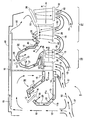
- the gas turbine 5 comprises a main combustion chamber 10, the Combustion chamber interior through a combustion chamber interior wall 11a is included.
- the main combustion chamber 10 is turned outside bounded by a combustion chamber outer wall 11b such that between the combustion chamber inner wall 11a and the combustion chamber outer wall 11b, a cooling air duct 20 is formed.
- Cooling air is introduced into the cooling air duct 20 of the main combustion chamber 10 15 fed, which the combustion chamber inner wall 11a on the cools the side facing away from the main combustion chamber 10.
- the cooling air 15 is through openings 16 in the interior of the main combustion chamber 10 fed where they are burning as an oxygen supplier promotes.
- the cooling air 15 is also by means of a Diffuser 17 through the guide vane 26 of the turbine stage 25 guided and thus cools the guide vane 26. After the Exit from the guide vane 26, the cooling air 15 at one Guide ring 28 passed to cool it.
- the cooling air 15 is in a cooling air duct 35 of the other Combustion chamber 34 initiated.
- a compressor gas mixture 14 becomes the further combustion chamber 34 fed to burned there by burners, not shown to become a secondary hot gas flow, which is then in the direction N emerges from the further combustion chamber 34.
- the cooling air 15 in the cooling air duct 35 of the further combustion chamber 34 is through openings 37 in the interior of the other Combustion chamber 34 initiated and promotes there as an oxygen supplier the combustion.
- the cooling air 15 becomes an overflow line 40 passed another turbine stage 27. It will go along one Guide ring 38 out, cools it and occurs then in a guide vane 29. Then the Cooling air 15 on the same side of the guide vane 29 who initiated it.
- the cooling air 15 emerging from the guide vane 29 is in the cooling air duct 35 fed to the further combustion chamber 35. Parts of the cooling air 15 pass through the openings 37 Coming from the guide vane 29 into the cooling air duct 35 were fed into the interior of the further combustion chamber 34 and promote combustion there.
- the cooling air 15 is also introduced into the blades 30, 32 be cool.
- the cooling air 15 is in this case on free end of the blades 30, 32 reflects and occurs the same side of the respective blade on which it has occurred. She will then be at the place of her exit fed to the guide vane 29 by means of a channel, occurs through this and is then in the cooling air duct fed to the further combustion chamber 34. From there it can then through the outlet opening 37 into the combustion chamber enter the further combustion chamber.
- the further combustion chamber 34 opens out with its auxiliary hot gas channel 45 behind stage 25 in the main hot gas duct 40. There the flowing in the direction of N mixes, from the additional combustion chamber 34 generated secondary hot gas flow with the main hot gas flow flowing in the direction of H, which of the Combustion chamber 10 is generated.
- This mixed flow passes through the guide vane 29 of the turbine stage 27 and drives the blade 32 of the turbine stage 27 on.
- Invention is practically the entire cooling air 15, which for Cooling of turbine stages 25 and 27 is used after Cooling process fed to a combustion.
- This is special achieved an increase in performance of the gas turbine without to have to increase the fuel supply.
- Furthermore are thus the thermal loads on the blades and the Emissions of pollutants, especially emissions of nitrogen oxides, the gas turbine despite the increase in performance not increased.
- by an inventive Gas turbine even a reduction in thermal Load on the blades and the pollutants emitted realizable.
Landscapes
- Engineering & Computer Science (AREA)
- Chemical & Material Sciences (AREA)
- Combustion & Propulsion (AREA)
- Mechanical Engineering (AREA)
- General Engineering & Computer Science (AREA)
- Turbine Rotor Nozzle Sealing (AREA)
Abstract
Description
- FIG
- eine Brennkammeranordnung einer erfindungsgemäßen Gasturbine.
Claims (6)
- Gasturbine (5) mit einer Hauptbrennkammer (10), einem Kühlsystem zur Luftkühlung mindestens der Leitschaufeln (26, 29) und Führungsringe (28, 38) verschiedener Stufen (25, 27) der Gasturbine (5) und/oder einem Hauptgaskanal,
dadurch gekennzeichnet,dass eine weitere Brennkammer (34) in Heißgashauptrichtung (H) hinter der Hauptbrennkammer (10) angeordnet ist, in welche die zur Kühlung einer vor der weiteren Brennkammer (34) angeordneten Stufe (25) der Gasturbine (5) verwendete Kühlluft (15) eingespeist ist. - Gasturbine nach Anspruch 1,
dadurch gekennzeichnet,dass die weitere Brennkammer (34) in Heißgasrichtung (H) hinter einer davor angeordneten Stufe (25) und vor einer danach angeordneten Stufe (27) in den Hauptgaskanal mündet. - Gasturbine nach einem der Ansprüche 1 oder 2,
dadurch gekennzeichnet,dass die weitere Brennkammer (34) ein geschlossenes Kühlsystem (35) aufweist, in welches die zur Kühlung einer davor angeordneten Stufe (25) der Gasturbine (5) verwendete Kühlluft (15) gespeist ist. - Gasturbine nach Anspruch 3,
dadurch gekennzeichnet,dass in das geschlossene Kühlsystem (35) zusätzlich die zur Kühlung einer in Heißgashauptrichtung (H) nach der weiteren Brennkammer angeordneten Stufe (27) der Gasturbine (5) benutzte Kühlluft (15) gespeist ist. - Gasturbine nach Anspruch 4,
dadurchgekennzeichnet,dass die nach der weiteren Brennkammer (34) angeordneten Stufe (27) mittels einer Überströmleitung (40), welche mit der vor der weiteren Brennkammer (34) angeordneten Stufe (25) kommuniziert, mit Kühlluft (15) versorgt ist. - Gasturbine nach einem der Ansprüche 1 bis 4,
dadurch gekennzeichnet,dass die weitere Brennkammer (34) zwischen Abschottwänden angeordnet ist, welche die weitere Brennkammer (34) von angrenzenden Bereichen der Turbine trennt, in denen durch Verdichter erzeugter Gasdruck herrscht.
Priority Applications (6)
| Application Number | Priority Date | Filing Date | Title |
|---|---|---|---|
| ES01107386T ES2261288T3 (es) | 2001-03-26 | 2001-03-26 | Turbina de gas. |
| EP01107386A EP1245804B1 (de) | 2001-03-26 | 2001-03-26 | Gasturbine |
| DE50109870T DE50109870D1 (de) | 2001-03-26 | 2001-03-26 | Gasturbine |
| JP2002078947A JP4146657B2 (ja) | 2001-03-26 | 2002-03-20 | ガスタービン |
| US10/104,083 US6691503B2 (en) | 2001-03-26 | 2002-03-21 | Gas turbine having first and second combustion chambers and cooling system |
| CNB021186871A CN1258643C (zh) | 2001-03-26 | 2002-03-26 | 燃气轮机 |
Applications Claiming Priority (1)
| Application Number | Priority Date | Filing Date | Title |
|---|---|---|---|
| EP01107386A EP1245804B1 (de) | 2001-03-26 | 2001-03-26 | Gasturbine |
Publications (2)
| Publication Number | Publication Date |
|---|---|
| EP1245804A1 true EP1245804A1 (de) | 2002-10-02 |
| EP1245804B1 EP1245804B1 (de) | 2006-05-24 |
Family
ID=8176933
Family Applications (1)
| Application Number | Title | Priority Date | Filing Date |
|---|---|---|---|
| EP01107386A Expired - Lifetime EP1245804B1 (de) | 2001-03-26 | 2001-03-26 | Gasturbine |
Country Status (6)
| Country | Link |
|---|---|
| US (1) | US6691503B2 (de) |
| EP (1) | EP1245804B1 (de) |
| JP (1) | JP4146657B2 (de) |
| CN (1) | CN1258643C (de) |
| DE (1) | DE50109870D1 (de) |
| ES (1) | ES2261288T3 (de) |
Cited By (4)
| Publication number | Priority date | Publication date | Assignee | Title |
|---|---|---|---|---|
| WO2007028693A1 (de) * | 2005-09-09 | 2007-03-15 | Alstom Technology Ltd | Kühlung einer gasturbogruppe mit zweiter brennkammer |
| FR2961857A1 (fr) * | 2010-06-28 | 2011-12-30 | Snecma | Tube d'alimentation en air de refroidissement d'une turbine d'un turbomoteur, et turbomoteur equipe d'un tel tube |
| DE10312971B4 (de) * | 2003-03-24 | 2017-04-06 | General Electric Technology Gmbh | Verfahren zum Betreiben einer Gasturbogruppe |
| EP3121371B1 (de) * | 2015-07-21 | 2020-10-28 | Rolls-Royce Deutschland Ltd & Co KG | Turbine mit gekühlten turbinenleitschaufeln |
Families Citing this family (27)
| Publication number | Priority date | Publication date | Assignee | Title |
|---|---|---|---|---|
| DE50106969D1 (de) * | 2001-03-30 | 2005-09-08 | Siemens Ag | Gekühlte Gasturbinenschaufel |
| EP1400751A1 (de) * | 2002-09-17 | 2004-03-24 | Siemens Aktiengesellschaft | Brennkammer für eine Gasturbine |
| EP1508680A1 (de) * | 2003-08-18 | 2005-02-23 | Siemens Aktiengesellschaft | Diffusor zwischen Verdichter und Brennkammer einer Gasturbine angeordnet |
| JP4495603B2 (ja) * | 2004-01-15 | 2010-07-07 | 株式会社日立製作所 | ガスタービン発電装置およびそれに用いる消音装置 |
| US7093446B2 (en) * | 2004-09-15 | 2006-08-22 | General Electric Company | Gas turbine engine having improved core system |
| US7096674B2 (en) * | 2004-09-15 | 2006-08-29 | General Electric Company | High thrust gas turbine engine with improved core system |
| US20080229749A1 (en) * | 2005-03-04 | 2008-09-25 | Michel Gamil Rabbat | Plug in rabbat engine |
| US20060196189A1 (en) * | 2005-03-04 | 2006-09-07 | Rabbat Michel G | Rabbat engine |
| US7303372B2 (en) * | 2005-11-18 | 2007-12-04 | General Electric Company | Methods and apparatus for cooling combustion turbine engine components |
| EP2229507B1 (de) * | 2007-12-29 | 2017-02-08 | General Electric Technology GmbH | Gasturbine |
| WO2009118245A1 (de) * | 2008-03-28 | 2009-10-01 | Alstom Technology Ltd | Leitschaufel für eine gasturbine sowie gasturbine mit einer solchen leitschaufel |
| US20090301054A1 (en) * | 2008-06-04 | 2009-12-10 | Simpson Stanley F | Turbine system having exhaust gas recirculation and reheat |
| US9297306B2 (en) * | 2008-09-11 | 2016-03-29 | General Electric Company | Exhaust gas recirculation system, turbomachine system having the exhaust gas recirculation system and exhaust gas recirculation control method |
| US8474266B2 (en) * | 2009-07-24 | 2013-07-02 | General Electric Company | System and method for a gas turbine combustor having a bleed duct from a diffuser to a fuel nozzle |
| GB0920094D0 (en) * | 2009-11-17 | 2009-12-30 | Alstom Technology Ltd | Reheat combustor for a gas turbine engine |
| EP2587021A1 (de) * | 2011-10-24 | 2013-05-01 | Siemens Aktiengesellschaft | Gasturbine und Verfahren zum Leiten von Druckflüssigkeit in eine Gasturbine |
| US8893512B2 (en) * | 2011-10-25 | 2014-11-25 | Siemens Energy, Inc. | Compressor bleed cooling fluid feed system |
| CN104204680B (zh) * | 2012-03-23 | 2016-01-06 | 阿尔斯通技术有限公司 | 燃烧装置 |
| EP2685171B1 (de) * | 2012-07-09 | 2018-03-21 | Ansaldo Energia Switzerland AG | Brenneranordnung |
| JP6013288B2 (ja) * | 2012-07-20 | 2016-10-25 | 株式会社東芝 | タービン、及び発電システム |
| US10094569B2 (en) | 2014-12-11 | 2018-10-09 | General Electric Company | Injecting apparatus with reheat combustor and turbomachine |
| US10107498B2 (en) | 2014-12-11 | 2018-10-23 | General Electric Company | Injection systems for fuel and gas |
| US10094571B2 (en) | 2014-12-11 | 2018-10-09 | General Electric Company | Injector apparatus with reheat combustor and turbomachine |
| US10094570B2 (en) | 2014-12-11 | 2018-10-09 | General Electric Company | Injector apparatus and reheat combustor |
| US9945562B2 (en) * | 2015-12-22 | 2018-04-17 | General Electric Company | Staged fuel and air injection in combustion systems of gas turbines |
| US20190017437A1 (en) * | 2017-07-13 | 2019-01-17 | General Electric Company | Continuous detonation gas turbine engine |
| CN108825380B (zh) * | 2018-05-28 | 2020-05-19 | 华中科技大学 | 一种涡轴发动机 |
Citations (8)
| Publication number | Priority date | Publication date | Assignee | Title |
|---|---|---|---|---|
| GB513151A (en) * | 1938-04-07 | 1939-10-04 | Sulzer Ag | Improvements in or relating to power plants comprising a gas turbine employing products of combustion and a compressor for compressing the combustion air |
| FR1063380A (fr) * | 1952-09-17 | 1954-05-03 | Perfectionnements aux turbo-machines à gaz | |
| US3315467A (en) * | 1965-03-11 | 1967-04-25 | Westinghouse Electric Corp | Reheat gas turbine power plant with air admission to the primary combustion zone of the reheat combustion chamber structure |
| GB2236145A (en) * | 1989-07-28 | 1991-03-27 | Gen Electric | Gas turbine engine steam cooling |
| US5083422A (en) | 1988-03-25 | 1992-01-28 | General Electric Company | Method of breach cooling |
| EP0595026A1 (de) * | 1992-10-26 | 1994-05-04 | Abb Research Ltd. | Verfahren für eine Mehrstufenverbrennung in Gasturbinen |
| DE19501471A1 (de) * | 1994-01-25 | 1995-08-10 | Kenzo Hoshino | Turbine, insbesondere Gasturbine |
| EP1028237A2 (de) * | 1999-02-01 | 2000-08-16 | ABB Alstom Power UK Ltd. | Gasturbinentriebwerk |
Family Cites Families (9)
| Publication number | Priority date | Publication date | Assignee | Title |
|---|---|---|---|---|
| NL70901C (de) * | 1945-01-23 | |||
| US2625793A (en) * | 1949-05-19 | 1953-01-20 | Westinghouse Electric Corp | Gas turbine apparatus with air-cooling means |
| US3703808A (en) * | 1970-12-18 | 1972-11-28 | Gen Electric | Turbine blade tip cooling air expander |
| US3973396A (en) * | 1974-10-16 | 1976-08-10 | United Turbine Ab & Co., Kommanditbolag | Gas turbine power plant |
| DE2728400C2 (de) * | 1977-06-24 | 1987-02-12 | Brown, Boveri & Cie Ag, 6800 Mannheim | Gasturbine |
| DE2728382C2 (de) * | 1977-06-24 | 1985-12-12 | Brown, Boveri & Cie Ag, 6800 Mannheim | Gasturbine |
| DE4210541A1 (de) * | 1992-03-31 | 1993-10-07 | Asea Brown Boveri | Verfahren zum Betrieb einer Gasturbogruppe |
| US5680767A (en) * | 1995-09-11 | 1997-10-28 | General Electric Company | Regenerative combustor cooling in a gas turbine engine |
| US5782076A (en) * | 1996-05-17 | 1998-07-21 | Westinghouse Electric Corporation | Closed loop air cooling system for combustion turbines |
-
2001
- 2001-03-26 ES ES01107386T patent/ES2261288T3/es not_active Expired - Lifetime
- 2001-03-26 DE DE50109870T patent/DE50109870D1/de not_active Expired - Fee Related
- 2001-03-26 EP EP01107386A patent/EP1245804B1/de not_active Expired - Lifetime
-
2002
- 2002-03-20 JP JP2002078947A patent/JP4146657B2/ja not_active Expired - Fee Related
- 2002-03-21 US US10/104,083 patent/US6691503B2/en not_active Expired - Fee Related
- 2002-03-26 CN CNB021186871A patent/CN1258643C/zh not_active Expired - Fee Related
Patent Citations (8)
| Publication number | Priority date | Publication date | Assignee | Title |
|---|---|---|---|---|
| GB513151A (en) * | 1938-04-07 | 1939-10-04 | Sulzer Ag | Improvements in or relating to power plants comprising a gas turbine employing products of combustion and a compressor for compressing the combustion air |
| FR1063380A (fr) * | 1952-09-17 | 1954-05-03 | Perfectionnements aux turbo-machines à gaz | |
| US3315467A (en) * | 1965-03-11 | 1967-04-25 | Westinghouse Electric Corp | Reheat gas turbine power plant with air admission to the primary combustion zone of the reheat combustion chamber structure |
| US5083422A (en) | 1988-03-25 | 1992-01-28 | General Electric Company | Method of breach cooling |
| GB2236145A (en) * | 1989-07-28 | 1991-03-27 | Gen Electric | Gas turbine engine steam cooling |
| EP0595026A1 (de) * | 1992-10-26 | 1994-05-04 | Abb Research Ltd. | Verfahren für eine Mehrstufenverbrennung in Gasturbinen |
| DE19501471A1 (de) * | 1994-01-25 | 1995-08-10 | Kenzo Hoshino | Turbine, insbesondere Gasturbine |
| EP1028237A2 (de) * | 1999-02-01 | 2000-08-16 | ABB Alstom Power UK Ltd. | Gasturbinentriebwerk |
Cited By (6)
| Publication number | Priority date | Publication date | Assignee | Title |
|---|---|---|---|---|
| DE10312971B4 (de) * | 2003-03-24 | 2017-04-06 | General Electric Technology Gmbh | Verfahren zum Betreiben einer Gasturbogruppe |
| WO2007028693A1 (de) * | 2005-09-09 | 2007-03-15 | Alstom Technology Ltd | Kühlung einer gasturbogruppe mit zweiter brennkammer |
| US7568335B2 (en) | 2005-09-09 | 2009-08-04 | Alstom Technology Ltd | Gas turbogroup |
| DE102005042889B4 (de) | 2005-09-09 | 2019-05-09 | Ansaldo Energia Switzerland AG | Gasturbogruppe |
| FR2961857A1 (fr) * | 2010-06-28 | 2011-12-30 | Snecma | Tube d'alimentation en air de refroidissement d'une turbine d'un turbomoteur, et turbomoteur equipe d'un tel tube |
| EP3121371B1 (de) * | 2015-07-21 | 2020-10-28 | Rolls-Royce Deutschland Ltd & Co KG | Turbine mit gekühlten turbinenleitschaufeln |
Also Published As
| Publication number | Publication date |
|---|---|
| DE50109870D1 (de) | 2006-06-29 |
| US20020148214A1 (en) | 2002-10-17 |
| EP1245804B1 (de) | 2006-05-24 |
| ES2261288T3 (es) | 2006-11-16 |
| JP2002322915A (ja) | 2002-11-08 |
| CN1378039A (zh) | 2002-11-06 |
| CN1258643C (zh) | 2006-06-07 |
| US6691503B2 (en) | 2004-02-17 |
| JP4146657B2 (ja) | 2008-09-10 |
Similar Documents
| Publication | Publication Date | Title |
|---|---|---|
| EP1245804A1 (de) | Gasturbine | |
| DE60026235T2 (de) | Gasturbine und deren Regelung | |
| DE2913548C2 (de) | Wellenkühlung für ein Gasturbinentriebwerk | |
| WO2004020905A1 (de) | Verfahren und vorrichtung zum verbrennen eines brennstoff-oxidator-gemischs | |
| EP1173664A1 (de) | Kühlluftsystem | |
| CH701454A2 (de) | Brennerrohr-Strömungskonditionierer. | |
| DE112010003300T5 (de) | Gasturbine und Verfahren zum Betreiben einer Gasturbine | |
| WO1999063204A1 (de) | Gasturbine sowie verfahren zur kühlung einer turbinenstufe | |
| CH705181A1 (de) | Verfahren zum Kühlen einer Gasturbinenanlage sowie Gasturbinenanlage zur Durchführung des Verfahrens. | |
| DE2554010A1 (de) | Vorrichtung und verfahren zur zufuehrung von kuehlluft zu turbinenleitschaufeln | |
| EP1162355A2 (de) | Verfahren zum Kühlen einer Gasturbinenanlage | |
| DE10035676A1 (de) | Gasturbine und Verfahren zum Betrieb einer Gasturbine | |
| EP2642098A1 (de) | Gasturbinenkraftwerk mit inhomogenem Eintrittsgas | |
| EP0879347B1 (de) | Verfahren zur entspannung eines rauchgasstroms in einer turbine sowie entsprechende turbine | |
| EP0928364A1 (de) | Kompensation des druckverlustes einer kühlluftführung in einer gasturbinenanlage | |
| EP0813668B1 (de) | Verfahren zur verbrennung eines brennstoffs in einer gasturbine sowie entsprechende gasturbine | |
| EP1249578A1 (de) | Kühlung einer Gasturbine | |
| DE3248439A1 (de) | Gasturbinentriebwerk mit gekuehlten schaufelspitzen | |
| CH707756A2 (de) | Brennstoffdüse zur Beschränkung von NOx-Emissionen für eine Diffusionsbrennkammereinrichtung. | |
| DE4330613A1 (de) | Verfahren und Vorrichtung zum Betrieb einer Gasturbine | |
| EP1167721A2 (de) | Verfahren zum Kühlen einer Gasturbinenanlage sowie Gasturbinenanlage zur Durchführung des Verfahrens | |
| WO2000017504A1 (de) | Brennstoffvorwärmung in einer gasturbine | |
| EP1847682A1 (de) | Verfahren zum Zuführen eines Fluides in den die Turbine durchströmenden Hauptgasstrom und dementsprechende Turbinenschaufel | |
| WO2006053825A1 (de) | Gasturbinenanlage und zugehörige brennkammer | |
| EP0928367A1 (de) | Mischung von zwei fluidströmen an einem verdichter |
Legal Events
| Date | Code | Title | Description |
|---|---|---|---|
| PUAI | Public reference made under article 153(3) epc to a published international application that has entered the european phase |
Free format text: ORIGINAL CODE: 0009012 |
|
| AK | Designated contracting states |
Kind code of ref document: A1 Designated state(s): AT BE CH CY DE DK ES FI FR GB GR IE IT LI LU MC NL PT SE TR |
|
| AX | Request for extension of the european patent |
Free format text: AL;LT;LV;MK;RO;SI |
|
| 17P | Request for examination filed |
Effective date: 20021104 |
|
| AKX | Designation fees paid |
Designated state(s): DE ES FR GB IT |
|
| 17Q | First examination report despatched |
Effective date: 20050408 |
|
| GRAP | Despatch of communication of intention to grant a patent |
Free format text: ORIGINAL CODE: EPIDOSNIGR1 |
|
| GRAS | Grant fee paid |
Free format text: ORIGINAL CODE: EPIDOSNIGR3 |
|
| GRAA | (expected) grant |
Free format text: ORIGINAL CODE: 0009210 |
|
| AK | Designated contracting states |
Kind code of ref document: B1 Designated state(s): DE ES FR GB IT |
|
| PG25 | Lapsed in a contracting state [announced via postgrant information from national office to epo] |
Ref country code: IT Free format text: LAPSE BECAUSE OF FAILURE TO SUBMIT A TRANSLATION OF THE DESCRIPTION OR TO PAY THE FEE WITHIN THE PRESCRIBED TIME-LIMIT;WARNING: LAPSES OF ITALIAN PATENTS WITH EFFECTIVE DATE BEFORE 2007 MAY HAVE OCCURRED AT ANY TIME BEFORE 2007. THE CORRECT EFFECTIVE DATE MAY BE DIFFERENT FROM THE ONE RECORDED. Effective date: 20060524 |
|
| REG | Reference to a national code |
Ref country code: GB Ref legal event code: FG4D Free format text: NOT ENGLISH |
|
| GBT | Gb: translation of ep patent filed (gb section 77(6)(a)/1977) |
Effective date: 20060607 |
|
| REF | Corresponds to: |
Ref document number: 50109870 Country of ref document: DE Date of ref document: 20060629 Kind code of ref document: P |
|
| REG | Reference to a national code |
Ref country code: ES Ref legal event code: FG2A Ref document number: 2261288 Country of ref document: ES Kind code of ref document: T3 |
|
| ET | Fr: translation filed | ||
| PLBE | No opposition filed within time limit |
Free format text: ORIGINAL CODE: 0009261 |
|
| STAA | Information on the status of an ep patent application or granted ep patent |
Free format text: STATUS: NO OPPOSITION FILED WITHIN TIME LIMIT |
|
| 26N | No opposition filed |
Effective date: 20070227 |
|
| PGFP | Annual fee paid to national office [announced via postgrant information from national office to epo] |
Ref country code: GB Payment date: 20080313 Year of fee payment: 8 Ref country code: IT Payment date: 20080326 Year of fee payment: 8 |
|
| PGFP | Annual fee paid to national office [announced via postgrant information from national office to epo] |
Ref country code: DE Payment date: 20080519 Year of fee payment: 8 Ref country code: ES Payment date: 20080416 Year of fee payment: 8 Ref country code: FR Payment date: 20080317 Year of fee payment: 8 |
|
| GBPC | Gb: european patent ceased through non-payment of renewal fee |
Effective date: 20090326 |
|
| REG | Reference to a national code |
Ref country code: FR Ref legal event code: ST Effective date: 20091130 |
|
| PG25 | Lapsed in a contracting state [announced via postgrant information from national office to epo] |
Ref country code: DE Free format text: LAPSE BECAUSE OF NON-PAYMENT OF DUE FEES Effective date: 20091001 |
|
| PG25 | Lapsed in a contracting state [announced via postgrant information from national office to epo] |
Ref country code: GB Free format text: LAPSE BECAUSE OF NON-PAYMENT OF DUE FEES Effective date: 20090326 Ref country code: FR Free format text: LAPSE BECAUSE OF NON-PAYMENT OF DUE FEES Effective date: 20091123 |
|
| REG | Reference to a national code |
Ref country code: ES Ref legal event code: FD2A Effective date: 20090327 |
|
| PG25 | Lapsed in a contracting state [announced via postgrant information from national office to epo] |
Ref country code: ES Free format text: LAPSE BECAUSE OF NON-PAYMENT OF DUE FEES Effective date: 20090327 |
|
| PG25 | Lapsed in a contracting state [announced via postgrant information from national office to epo] |
Ref country code: IT Free format text: LAPSE BECAUSE OF NON-PAYMENT OF DUE FEES Effective date: 20090326 |