EP1245737A2 - Rüttler mit einem Hydraulikantrieb - Google Patents
Rüttler mit einem Hydraulikantrieb Download PDFInfo
- Publication number
- EP1245737A2 EP1245737A2 EP02000980A EP02000980A EP1245737A2 EP 1245737 A2 EP1245737 A2 EP 1245737A2 EP 02000980 A EP02000980 A EP 02000980A EP 02000980 A EP02000980 A EP 02000980A EP 1245737 A2 EP1245737 A2 EP 1245737A2
- Authority
- EP
- European Patent Office
- Prior art keywords
- fluid
- hydraulic
- lubrication
- circuit
- construction machine
- Prior art date
- Legal status (The legal status is an assumption and is not a legal conclusion. Google has not performed a legal analysis and makes no representation as to the accuracy of the status listed.)
- Granted
Links
Images
Classifications
-
- B—PERFORMING OPERATIONS; TRANSPORTING
- B06—GENERATING OR TRANSMITTING MECHANICAL VIBRATIONS IN GENERAL
- B06B—METHODS OR APPARATUS FOR GENERATING OR TRANSMITTING MECHANICAL VIBRATIONS OF INFRASONIC, SONIC, OR ULTRASONIC FREQUENCY, e.g. FOR PERFORMING MECHANICAL WORK IN GENERAL
- B06B1/00—Methods or apparatus for generating mechanical vibrations of infrasonic, sonic, or ultrasonic frequency
- B06B1/18—Methods or apparatus for generating mechanical vibrations of infrasonic, sonic, or ultrasonic frequency wherein the vibrator is actuated by pressure fluid
- B06B1/186—Methods or apparatus for generating mechanical vibrations of infrasonic, sonic, or ultrasonic frequency wherein the vibrator is actuated by pressure fluid operating with rotary unbalanced masses
-
- E—FIXED CONSTRUCTIONS
- E02—HYDRAULIC ENGINEERING; FOUNDATIONS; SOIL SHIFTING
- E02D—FOUNDATIONS; EXCAVATIONS; EMBANKMENTS; UNDERGROUND OR UNDERWATER STRUCTURES
- E02D7/00—Methods or apparatus for placing sheet pile bulkheads, piles, mouldpipes, or other moulds
- E02D7/18—Placing by vibrating
Definitions
- the invention relates to a construction machine, in particular one Vibrator, with at least one hydraulic drive, which together with a hydraulic pump in a hydraulic circuit is arranged, and at least one transmission in which a fluid is provided for lubrication and / or cooling, which circulates in a lubrication circuit.
- Such construction machines have long been used in civil engineering. Such machines usually have a hydraulic motor because such a hydraulic drive both is robust, as well as the necessary high torque outputs can muster. With a vibrator, the hydraulic motor a gear driven with eccentric shafts. The Eccentric shafts of the gearbox are used to generate a targeted Vibration, for example, for insertion of ramming material is used.
- the invention has for its object to develop such a machine so that it is particularly simple and robust with the same or even improved functionality.
- the object is achieved by a construction machine, in particular a vibrator with the features of the claim 1 solved.
- Preferred embodiments of the invention are in the dependent claims.
- the machine according to the invention is characterized in that that the hydraulic circuit is connected to the lubrication circuit and that the fluid is simultaneously a hydraulic fluid is provided.
- the construction of a construction machine is simplified, especially a vibrator considerably.
- Fluid circuits with the appropriate facilities for example for pumping, cooling, filtering, monitoring, and Expansion tank, etc.
- a single combined fluid circuit is provided, which for both hydraulic drives and lubrication responsible is.
- an oil can be used as the fluid both the necessary properties of a hydraulic fluid in terms of compressibility as well as properties a lubricating oil, especially with regard to Lubrication and cooling fulfilled.
- a distributor block represents one robust connection point for the two circuits and basically enables existing ones Machines can be retrofitted.
- This arrangement is preferred according to the invention further developed by the fact that a hydraulic pump common supply line leads to the distributor block, wherein the hydraulic pump both the hydraulic circuit as well also supplies the lubrication circuit with fluid. So it is just a single feed line from the hydraulic pump to the central distribution point, the distribution block.
- a flow control valve and / or a Pressure switches are arranged in the lubrication circuit between the manifold and the transmission.
- the flow control valve serves as one Throttle, with which the relatively high pressure in the hydraulic circuit, which are up to several 100 bar can, to a necessary, lower pressure value of the Lubrication circuit is reduced.
- the pressure in that The lubrication cycle can be ten times smaller than the pressure in the hydraulic circuit or even just be a few bar.
- the pressure switch is used for monitoring of pressure, being by the combination of the two Circuits total the effort for control and management the total number of fluid circuits is reduced.
- the invention is further developed by that the gearbox will accommodate a floor pan of the fluid and that a lubrication pump is provided is through which fluid can be pumped out of the floor pan.
- the invention is thus also for conventional, vented Gear can be used.
- the additional lubrication pump must be used only the relatively low output for the return the fluid from the gear back to the fluid reservoir muster.
- a particularly safe operation of the device according to the invention is given by the fact that in the lubrication circuit between the distributor block and the gearbox a flush valve is provided which has an inflow of fluid into the transmission prevented when the hydraulic drive is at a standstill.
- the Flush valve can be used with the manifold and / or be fed back at least one hydraulic drive, so that only when operating the hydraulic drive fluid in the Gear can get. With the hydraulic drive at a standstill or with a corresponding reduction in pressure The flushing valve becomes the fluid supply to the hydraulic drive closed so that no fluid in from the manifold block the gearbox can get more.
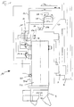
- a construction machine according to the invention is based on a vibrator 10 described, the essential components in Fig. 1 are shown.
- a mast 2 On a mast 2 a not shown
- the carriage is guided by a sliding carriage 3 to which a housing of the gear 22 of the vibrator 10 is attached is.
- a bracket 4 At the lower end of the housing of the transmission 22nd a bracket 4 is attached, which in particular for Picking up and loading ramming serves.
- Such one Jogger is generally known.
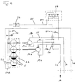
- the gear 22 includes for generating vibrations Eccentric 5, which are indicated schematically in Fig. 2.
- the eccentrics 5 are over waves and meshing with each other Gear elements in connection and via two hydraulic motors 12a, 12b driven in rotation.
- the unbalance generate the eccentrics 5 with a rotating movement desired vibrations, which lead to the introduction of ramming material can be used.
- the hydraulic motors 12a, 12b are on the outside of the housing of the transmission 22nd flanged. Below the hydraulic motors 12a, 12b further attached a lubrication pump 23, its function described below in connection with Figures 1 and 2 becomes.
- a hydraulic pump 14 Via a hydraulic pump 14, only shown schematically becomes a fluid, which according to the invention both as a hydraulic fluid also serves as a lubricating oil, over a common one Feed line 32 led to a distributor block 30, which is a line connection between a hydraulic circuit 15 and a lubrication circuit 25.
- the two hydraulic drives 12a, 12b via hydraulic feed lines 17a, 17b with the Fluid supplied.
- the fluid is returned via Return lines 19a, 19b to the distributor block 30 which the fluid takes place via a first return line 34.
- the torques of the hydraulic motors 12a, 12b are as intended by means of appropriate drive shafts transmitted to the shafts of the transmission 22.
- the fluid from the manifold block 30 via the two alternative feed lines 27a passed to a purge valve 28.
- the purge valve 28 is like this trained and switched that this only opened is when at least one of the two hydraulic motors 12a, 12b is in operation. Should not be on either line 27a there is pressure and therefore no hydraulic motor 12a, 12b be in operation, the purge valve 28 closes and prevents thus the introduction of fluid into the gear 22.
- the purge valve 28 ensures that during operation at least one of the two hydraulic motors 12a, 12b fluid passed for lubrication and cooling in the gear 22 becomes. Forwarding the fluid from the purge valve 28 takes place via the lubrication lines 27b and 27c, between which a flow control valve 24 is interposed.
- the Flow control valve 24 essentially has the function of a adjustable throttle, with which both the amount of Fluid supply and the fluid pressure can be controlled can. For example, about the flow control valve 20 to 25 liters of fluid per minute in the gearbox 22 to the desired bearings and cooling points are injected. The fluid pressure is reduced from a few 100 bar to a few bar reduced.
- a pressure switch 26 is arranged, which for measurement and Monitoring the line pressure serves.
- the fluid is used for lubrication and cooling to the desired Places initiated in the transmission 22, where the fluid according to gravity in no closer floor pan shown collects. From this it becomes by means of a lubrication line 27d is pumped out via a lubrication pump 23, which directly through the gear 22 via a corresponding drive shaft is driven. To this This ensures that the lubrication pump 23 only then is operated when the transmission 22 is also put into operation is.
- the lubrication pump 23 provides the sufficient Pump pressure is available to transfer the fluid through a second Return return line 36.
- Processing facilities which in particular the Cooling, filtering, etc.
- a return or expansion tank as a fluid reservoir provided, from which the hydraulic pump 14 then Feed the fluid back into the combined fluid circuit.
Landscapes
- Engineering & Computer Science (AREA)
- Life Sciences & Earth Sciences (AREA)
- General Life Sciences & Earth Sciences (AREA)
- Mining & Mineral Resources (AREA)
- Paleontology (AREA)
- Civil Engineering (AREA)
- General Engineering & Computer Science (AREA)
- Structural Engineering (AREA)
- Mechanical Engineering (AREA)
- Fluid-Pressure Circuits (AREA)
- General Details Of Gearings (AREA)
Abstract
Description
- Fig. 1
- eine Prinzipskizze zu einem erfindungsgemäß ausgestalteten Rüttler und
- Fig. 2
- ein Hydraulikplan zu der Ausführungsform von Fig. 1.
Claims (8)
- Baumaschine, insbesondere Rüttler, mitdadurch gekennzeichnet,mindestens einem Hydraulikantrieb (12), welcher zusammen mit einer Hydraulikpumpe (14) in einem Hydraulikkreislauf (15) angeordnet ist, undmindestens einem Getriebe (22), in welchem zur Schmierung und/oder Kühlung ein Fluid vorgesehen ist, welches in einem Schmierkreislauf (25) zirkuliert,dass der Hydraulikkreislauf (15) mit dem Schmierkreislauf (25) verbunden ist unddass das Fluid gleichzeitig als Hydraulikfluid vorgesehen ist.
- Baumaschinen nach Anspruch 1,
dadurch gekennzeichnet, dass der Hydraulikkreislauf (15) und der Schmierkreislauf (25) über einen Verteilerblock (30) miteinander leitungsverbunden sind. - Baumaschine nach Anspruch 2,
dadurch gekennzeichnet, dass von der Hydraulikpumpe (14) eine gemeinsame Zuführleitung (32) zu dem Verteilerblock (30) führt, wobei die Hydraulikpumpe (14) sowohl den Hydraulikkreislauf (15) als auch den Schmierkreislauf (25) mit Fluid versorgt. - Baumaschine nach Anspruch 2 oder 3,
dadurch gekennzeichnet, dass im Schmierkreislauf (25) zwischen dem Verteilerblock (30) und dem Getriebe (22) ein Stromregelventil (24) und/oder ein Druckschalter (26) angeordnet sind. - Baumaschine nach einem der Ansprüche 1 bis 4,
dadurch gekennzeichnet, dass das Getriebe (22) eine Bodenwanne zur Aufnahme des Fluids aufweist und
dass eine Schmierpumpe (23) vorgesehen ist, durch welche Fluid aus der Bodenwanne abpumpbar ist. - Baumaschine nach einem der Ansprüche 1 bis 5,
dadurch gekennzeichnet, dass zur Rückführung des Fluides von dem mindestens einen Hydraulikantrieb (12) und/oder von der Schmierpumpe (23) diese mit einem Rücklaufbehälter leitungsverbunden sind, aus welchen das Fluid über die Hydraulikpumpe (14) abführbar ist. - Baumaschine nach Anspruch 6,
dadurch gekennzeichnet, dass zwischen dem Rücklaufbehälter und der Hydraulikpumpe (14) ein Kühler und/oder Filter angeordnet sind. - Baumaschine nach einem der Ansprüche 2 bis 7,
dadurch gekennzeichnet, dass im Schmierkreislauf (25) zwischen dem Verteilerblock (30) und dem Getriebe (22) ein Spülventil (28) vorgesehen ist, welches einen Zufluss von Fluid in das Getriebe (22) bei stillstehendem Hydraulikantrieb (12) verhindert.
Applications Claiming Priority (2)
| Application Number | Priority Date | Filing Date | Title |
|---|---|---|---|
| DE10115260 | 2001-03-28 | ||
| DE2001115260 DE10115260C2 (de) | 2001-03-28 | 2001-03-28 | Baumaschine zur Erzeugung von Schwingungen |
Publications (4)
| Publication Number | Publication Date |
|---|---|
| EP1245737A2 true EP1245737A2 (de) | 2002-10-02 |
| EP1245737A3 EP1245737A3 (de) | 2002-12-11 |
| EP1245737B1 EP1245737B1 (de) | 2007-12-12 |
| EP1245737B2 EP1245737B2 (de) | 2015-09-30 |
Family
ID=7679370
Family Applications (1)
| Application Number | Title | Priority Date | Filing Date |
|---|---|---|---|
| EP02000980.9A Expired - Lifetime EP1245737B2 (de) | 2001-03-28 | 2002-01-16 | Rüttler mit einem Hydraulikantrieb |
Country Status (2)
| Country | Link |
|---|---|
| EP (1) | EP1245737B2 (de) |
| DE (2) | DE10115260C2 (de) |
Cited By (2)
| Publication number | Priority date | Publication date | Assignee | Title |
|---|---|---|---|---|
| EP1990100A1 (de) * | 2007-05-10 | 2008-11-12 | BAUER Maschinen GmbH | Baumaschine zum Erzeugen von Schwingungen |
| EP3081700B1 (de) | 2015-04-13 | 2018-06-13 | Liebherr-Werk Nenzing GmbH | Rüttelvorrichtung |
Families Citing this family (1)
| Publication number | Priority date | Publication date | Assignee | Title |
|---|---|---|---|---|
| DE102006053093A1 (de) * | 2006-11-10 | 2008-05-15 | Bomag Gmbh | Ölschmierung |
Family Cites Families (4)
| Publication number | Priority date | Publication date | Assignee | Title |
|---|---|---|---|---|
| US4039167A (en) * | 1976-08-02 | 1977-08-02 | Zinga Industries Inc. | Hydraulic vibrator |
| US4861252A (en) * | 1986-09-11 | 1989-08-29 | International Pipe Machinery Corp. | Vibrator type concrete pipe making machines having combined lubrication and cooling system |
| US5355964A (en) * | 1993-07-12 | 1994-10-18 | White John L | Pile driving and/or pile pulling vibratory assembly with counterweights |
| AU692479B2 (en) * | 1993-11-30 | 1998-06-11 | Sakai Heavy Industries, Ltd. | Vibrating mechanism and apparatus for generating vibrations for a vibration compacting roller with a variable amplitude |
-
2001
- 2001-03-28 DE DE2001115260 patent/DE10115260C2/de not_active Expired - Fee Related
-
2002
- 2002-01-16 EP EP02000980.9A patent/EP1245737B2/de not_active Expired - Lifetime
- 2002-01-16 DE DE50211335T patent/DE50211335D1/de not_active Expired - Lifetime
Cited By (4)
| Publication number | Priority date | Publication date | Assignee | Title |
|---|---|---|---|---|
| EP1990100A1 (de) * | 2007-05-10 | 2008-11-12 | BAUER Maschinen GmbH | Baumaschine zum Erzeugen von Schwingungen |
| CN101302762B (zh) * | 2007-05-10 | 2010-09-29 | 包尔机械有限公司 | 施工机械 |
| US7980788B2 (en) | 2007-05-10 | 2011-07-19 | Bauer Maschinen Gmbh | Construction machine |
| EP3081700B1 (de) | 2015-04-13 | 2018-06-13 | Liebherr-Werk Nenzing GmbH | Rüttelvorrichtung |
Also Published As
| Publication number | Publication date |
|---|---|
| DE50211335D1 (de) | 2008-01-24 |
| EP1245737B2 (de) | 2015-09-30 |
| EP1245737B1 (de) | 2007-12-12 |
| DE10115260A1 (de) | 2002-10-24 |
| DE10115260C2 (de) | 2003-04-30 |
| EP1245737A3 (de) | 2002-12-11 |
Similar Documents
| Publication | Publication Date | Title |
|---|---|---|
| EP1643123B1 (de) | Automatische Schmiereinrichtung | |
| EP2123831A2 (de) | Bagger-Zusatzgerät | |
| DE202008000748U1 (de) | Schmierstoffpumpe zur Förderung von Schmierstoff | |
| DE102019117643B4 (de) | Mit einem Schmiersystem versehene Gelenkwellenanordnung | |
| DE102016114403A1 (de) | Zapfwellenölsystem, das der ausrückkupplung ölablass und drucköl bereitstellt | |
| EP1990100B1 (de) | Baumaschine zum Erzeugen von Schwingungen | |
| WO2024256128A1 (de) | Kühl- und schmiersystem | |
| EP2577112A1 (de) | Verfahren und einrichtung zur innenbeölung einer koaxial zur ölpumpe eines getriebes angeordneten und die ölpumpe antreibenden getriebewelle | |
| EP1245737B2 (de) | Rüttler mit einem Hydraulikantrieb | |
| EP2933533A1 (de) | Kegelradvorstufe eines Planetengetriebes | |
| EP3365497B1 (de) | Antriebseinrichtung für eine baumaschine, sowie baumaschine | |
| DE102021208683B3 (de) | Verfahren zum Reparieren einer Getriebeanordnung | |
| DE10243675B3 (de) | Exzenterschneckenpumpe mit Austauscheinheit | |
| DE202005019485U1 (de) | Schmierstoffpumpe | |
| EP0691234B2 (de) | Verfahren und Einrichtung zur Kühlung mindestens einer Fahrpumpe und mindestens eines Fahrmotors eines hydrostatischen Fahrantriebes | |
| DE3904349A1 (de) | Aggregat zur erzeugung von hydraulischer kraft | |
| DE3307790A1 (de) | Aggregat aus zwei zahnringpumpen | |
| EP3215762B1 (de) | Antriebseinrichtung für ein kraftfahrzeug | |
| DE102024136090B3 (de) | Traktionsantrieb mit Schmiermittelfördereinrichtung, Verfahren zum Betreiben eines Traktionsantriebs und Verwendung des Traktionsantriebs in einem Kraftfahrzeug | |
| DE102005022161A1 (de) | Vorrichtung zum Schmieren von Komponenten eines Kraftfahrzeugs | |
| EP3081700B1 (de) | Rüttelvorrichtung | |
| DE3510596A1 (de) | Strassenfraese | |
| DE102021204426A1 (de) | Antriebsanordnung und Fahrzeug mit einer solchen Antriebsanordnung | |
| DE102020126329A1 (de) | Getriebevorrichtung mit Schmiermittelhaushalt und Verfahren zum Betrieb | |
| EP4705660A1 (de) | Getriebe mit einem verdrängungskörper für einen antriebsstrang |
Legal Events
| Date | Code | Title | Description |
|---|---|---|---|
| PUAI | Public reference made under article 153(3) epc to a published international application that has entered the european phase |
Free format text: ORIGINAL CODE: 0009012 |
|
| AK | Designated contracting states |
Kind code of ref document: A2 Designated state(s): AT BE CH CY DE DK ES FI FR GB GR IE IT LI LU MC NL PT SE TR |
|
| AX | Request for extension of the european patent |
Free format text: AL;LT;LV;MK;RO;SI |
|
| PUAL | Search report despatched |
Free format text: ORIGINAL CODE: 0009013 |
|
| AK | Designated contracting states |
Kind code of ref document: A3 Designated state(s): AT BE CH CY DE DK ES FI FR GB GR IE IT LI LU MC NL PT SE TR |
|
| AX | Request for extension of the european patent |
Free format text: AL;LT;LV;MK;RO;SI |
|
| RIC1 | Information provided on ipc code assigned before grant |
Free format text: 7E 02D 7/18 A, 7B 06B 1/18 B, 7B 06B 1/16 B |
|
| 17P | Request for examination filed |
Effective date: 20021203 |
|
| AKX | Designation fees paid |
Designated state(s): DE FR GB IT NL |
|
| 17Q | First examination report despatched |
Effective date: 20050614 |
|
| GRAP | Despatch of communication of intention to grant a patent |
Free format text: ORIGINAL CODE: EPIDOSNIGR1 |
|
| GRAS | Grant fee paid |
Free format text: ORIGINAL CODE: EPIDOSNIGR3 |
|
| GRAA | (expected) grant |
Free format text: ORIGINAL CODE: 0009210 |
|
| AK | Designated contracting states |
Kind code of ref document: B1 Designated state(s): DE FR GB IT NL |
|
| REG | Reference to a national code |
Ref country code: GB Ref legal event code: FG4D Free format text: NOT ENGLISH |
|
| REF | Corresponds to: |
Ref document number: 50211335 Country of ref document: DE Date of ref document: 20080124 Kind code of ref document: P |
|
| ET | Fr: translation filed | ||
| PLBI | Opposition filed |
Free format text: ORIGINAL CODE: 0009260 |
|
| PLAX | Notice of opposition and request to file observation + time limit sent |
Free format text: ORIGINAL CODE: EPIDOSNOBS2 |
|
| 26 | Opposition filed |
Opponent name: ABI ANLAGENTECHNIK-BAUMASCHINEN-INDUSTRIEBEDARF MA Effective date: 20080911 |
|
| NLR1 | Nl: opposition has been filed with the epo |
Opponent name: ABI ANLAGENTECHNIK-BAUMASCHINEN-INDUSTRIEBEDARF MA |
|
| PLBB | Reply of patent proprietor to notice(s) of opposition received |
Free format text: ORIGINAL CODE: EPIDOSNOBS3 |
|
| PLAY | Examination report in opposition despatched + time limit |
Free format text: ORIGINAL CODE: EPIDOSNORE2 |
|
| PLAH | Information related to despatch of examination report in opposition + time limit modified |
Free format text: ORIGINAL CODE: EPIDOSCORE2 |
|
| PLAH | Information related to despatch of examination report in opposition + time limit modified |
Free format text: ORIGINAL CODE: EPIDOSCORE2 |
|
| PLBC | Reply to examination report in opposition received |
Free format text: ORIGINAL CODE: EPIDOSNORE3 |
|
| PLAY | Examination report in opposition despatched + time limit |
Free format text: ORIGINAL CODE: EPIDOSNORE2 |
|
| PLBC | Reply to examination report in opposition received |
Free format text: ORIGINAL CODE: EPIDOSNORE3 |
|
| PGFP | Annual fee paid to national office [announced via postgrant information from national office to epo] |
Ref country code: IT Payment date: 20150121 Year of fee payment: 14 |
|
| PLAB | Opposition data, opponent's data or that of the opponent's representative modified |
Free format text: ORIGINAL CODE: 0009299OPPO |
|
| R26 | Opposition filed (corrected) |
Opponent name: ABI ANLAGENTECHNIK-BAUMASCHINEN-INDUSTRIEBEDARF MA Effective date: 20080911 |
|
| PUAH | Patent maintained in amended form |
Free format text: ORIGINAL CODE: 0009272 |
|
| STAA | Information on the status of an ep patent application or granted ep patent |
Free format text: STATUS: PATENT MAINTAINED AS AMENDED |
|
| 27A | Patent maintained in amended form |
Effective date: 20150930 |
|
| AK | Designated contracting states |
Kind code of ref document: B2 Designated state(s): DE FR GB IT NL |
|
| REG | Reference to a national code |
Ref country code: DE Ref legal event code: R102 Ref document number: 50211335 Country of ref document: DE |
|
| REG | Reference to a national code |
Ref country code: FR Ref legal event code: PLFP Year of fee payment: 15 |
|
| REG | Reference to a national code |
Ref country code: NL Ref legal event code: FP |
|
| PG25 | Lapsed in a contracting state [announced via postgrant information from national office to epo] |
Ref country code: IT Free format text: LAPSE BECAUSE OF NON-PAYMENT OF DUE FEES Effective date: 20160116 |
|
| REG | Reference to a national code |
Ref country code: FR Ref legal event code: PLFP Year of fee payment: 16 |
|
| REG | Reference to a national code |
Ref country code: FR Ref legal event code: PLFP Year of fee payment: 17 |
|
| REG | Reference to a national code |
Ref country code: DE Ref legal event code: R082 Ref document number: 50211335 Country of ref document: DE Representative=s name: WUNDERLICH & HEIM PATENTANWAELTE PARTNERSCHAFT, DE |
|
| PGFP | Annual fee paid to national office [announced via postgrant information from national office to epo] |
Ref country code: FR Payment date: 20210121 Year of fee payment: 20 Ref country code: NL Payment date: 20210120 Year of fee payment: 20 |
|
| PGFP | Annual fee paid to national office [announced via postgrant information from national office to epo] |
Ref country code: DE Payment date: 20210126 Year of fee payment: 20 Ref country code: GB Payment date: 20210122 Year of fee payment: 20 |
|
| REG | Reference to a national code |
Ref country code: DE Ref legal event code: R071 Ref document number: 50211335 Country of ref document: DE |
|
| REG | Reference to a national code |
Ref country code: NL Ref legal event code: MK Effective date: 20220115 |
|
| REG | Reference to a national code |
Ref country code: GB Ref legal event code: PE20 Expiry date: 20220115 |
|
| PG25 | Lapsed in a contracting state [announced via postgrant information from national office to epo] |
Ref country code: GB Free format text: LAPSE BECAUSE OF EXPIRATION OF PROTECTION Effective date: 20220115 |