EP1245520A1 - Anzeigeeinrichtung - Google Patents
Anzeigeeinrichtung Download PDFInfo
- Publication number
- EP1245520A1 EP1245520A1 EP02005798A EP02005798A EP1245520A1 EP 1245520 A1 EP1245520 A1 EP 1245520A1 EP 02005798 A EP02005798 A EP 02005798A EP 02005798 A EP02005798 A EP 02005798A EP 1245520 A1 EP1245520 A1 EP 1245520A1
- Authority
- EP
- European Patent Office
- Prior art keywords
- display device
- electroluminescent
- indicator
- film
- frame
- Prior art date
- Legal status (The legal status is an assumption and is not a legal conclusion. Google has not performed a legal analysis and makes no representation as to the accuracy of the status listed.)
- Granted
Links
- 239000000853 adhesive Substances 0.000 claims abstract description 5
- 230000001070 adhesive effect Effects 0.000 claims abstract description 5
- 238000005401 electroluminescence Methods 0.000 claims description 11
- 238000009434 installation Methods 0.000 claims description 4
- 239000010408 film Substances 0.000 description 27
- 239000011888 foil Substances 0.000 description 4
- 239000000049 pigment Substances 0.000 description 4
- 230000000007 visual effect Effects 0.000 description 4
- 238000005516 engineering process Methods 0.000 description 3
- 239000011521 glass Substances 0.000 description 3
- 238000007650 screen-printing Methods 0.000 description 3
- 102100040577 Dermatan-sulfate epimerase-like protein Human genes 0.000 description 2
- 101000816741 Homo sapiens Dermatan-sulfate epimerase-like protein Proteins 0.000 description 2
- 239000012876 carrier material Substances 0.000 description 2
- 238000010276 construction Methods 0.000 description 2
- 230000001419 dependent effect Effects 0.000 description 2
- 238000005286 illumination Methods 0.000 description 2
- 238000004519 manufacturing process Methods 0.000 description 2
- 230000005855 radiation Effects 0.000 description 2
- CJDNEKOMKXLSBN-UHFFFAOYSA-N 1-chloro-3-(4-chlorophenyl)benzene Chemical compound C1=CC(Cl)=CC=C1C1=CC=CC(Cl)=C1 CJDNEKOMKXLSBN-UHFFFAOYSA-N 0.000 description 1
- OKTJSMMVPCPJKN-UHFFFAOYSA-N Carbon Chemical compound [C] OKTJSMMVPCPJKN-UHFFFAOYSA-N 0.000 description 1
- 208000032041 Hearing impaired Diseases 0.000 description 1
- BQCADISMDOOEFD-UHFFFAOYSA-N Silver Chemical compound [Ag] BQCADISMDOOEFD-UHFFFAOYSA-N 0.000 description 1
- HCHKCACWOHOZIP-UHFFFAOYSA-N Zinc Chemical compound [Zn] HCHKCACWOHOZIP-UHFFFAOYSA-N 0.000 description 1
- WNROFYMDJYEPJX-UHFFFAOYSA-K aluminium hydroxide Chemical compound [OH-].[OH-].[OH-].[Al+3] WNROFYMDJYEPJX-UHFFFAOYSA-K 0.000 description 1
- 230000004397 blinking Effects 0.000 description 1
- 239000003990 capacitor Substances 0.000 description 1
- 239000003795 chemical substances by application Substances 0.000 description 1
- 238000004891 communication Methods 0.000 description 1
- 230000000295 complement effect Effects 0.000 description 1
- 238000005538 encapsulation Methods 0.000 description 1
- 229910002804 graphite Inorganic materials 0.000 description 1
- 239000010439 graphite Substances 0.000 description 1
- 230000001771 impaired effect Effects 0.000 description 1
- AMGQUBHHOARCQH-UHFFFAOYSA-N indium;oxotin Chemical compound [In].[Sn]=O AMGQUBHHOARCQH-UHFFFAOYSA-N 0.000 description 1
- 238000004020 luminiscence type Methods 0.000 description 1
- 239000011159 matrix material Substances 0.000 description 1
- 239000012528 membrane Substances 0.000 description 1
- 229910052751 metal Inorganic materials 0.000 description 1
- 239000002184 metal Substances 0.000 description 1
- 238000000034 method Methods 0.000 description 1
- 230000003287 optical effect Effects 0.000 description 1
- 244000052769 pathogen Species 0.000 description 1
- 230000001717 pathogenic effect Effects 0.000 description 1
- 238000009877 rendering Methods 0.000 description 1
- 229910052709 silver Inorganic materials 0.000 description 1
- 239000004332 silver Substances 0.000 description 1
- 239000010409 thin film Substances 0.000 description 1
- 229910052725 zinc Inorganic materials 0.000 description 1
- 239000011701 zinc Substances 0.000 description 1
Images


Classifications
-
- B—PERFORMING OPERATIONS; TRANSPORTING
- B66—HOISTING; LIFTING; HAULING
- B66B—ELEVATORS; ESCALATORS OR MOVING WALKWAYS
- B66B3/00—Applications of devices for indicating or signalling operating conditions of elevators
- B66B3/002—Indicators
- B66B3/004—Mechanical devices that can be illuminated
Definitions
- the invention relates to a display device, the Display device an electroluminescent indicator and has a sound reproducing apparatus.
- a Device meant the rendering of visual and / or acoustic information allowed.
- All devices can be understood with sound reproduction apparatus, which convert electrical signals into acoustic, audible ones for example in words, music, special sounds and such further.
- EP 0 403 232 describes an electroluminescence Display system for an elevator known that both Electroluminescent screen for the visual display of Elevator information as well as a speaker for has acoustic reproduction of elevator information.
- the electroluminescent screen is designed pixel-like and has a glass plate on its front or Luminous side on.
- the speaker is on the same Level as the electroluminescent screen but in one some distance from it.
- the invention is based on an object To propose a display device of the type mentioned at the outset, which does not have the aforementioned disadvantages and is more space-saving.
- the sound player is included connected to the electroluminescent indicator.
- the display device according to the invention can have a compact design.
- the Sound reproduction apparatus and the electroluminescence indicator can be installed in one piece.
- the Sound reproduction apparatus with the electroluminescence indicator connected by means of an adhesive. This leads to a simple and uncomplicated assembly of the Electroluminescent indicator with the sound reproducer.
- the Sound reproduction apparatus and the electroluminescence indicator arranged one behind the other. This is advantageous Embodiment the fact that there is only space in the Depth and not width is necessary.
- the projection of the The electroluminescence indicator on a surface determines the required size of the basic area for the whole Display means.
- the sound player and the electroluminescent indicator can be arranged between a frame and a housing his. This ensures a stable cohesion of the Electro-luminescence indicator and the sound reproduction apparatus in the display device.
- the sound reproduction apparatus can also be used as a flat speaker be trained. This leads to a thin design of the Display means. These types of speakers can be used in simply glued to the electroluminescent indicator be, their high quality properties not get lost.
- the Electroluminescent display based on the principle of Thick-film electroluminescence built up. This has the Advantage of being on the front of the electroluminescent display there is no glass plate, resulting in a space-saving construction and an inexpensive manufacturability leads.
- the light side is very thin and can be easily glued in front of a sound reproduction apparatus. Furthermore, such EL lamps generate a flat illumination, which lead to homogeneous lighting.
- the electroluminescent indicator can also be used as Electroluminescent lamp can be formed.
- This Embodiment allows the use of a single EL lamp, which is easy to control. Two are enough Connections to control the EL lamp.
- the display device has fixing means, so that the display device on a wall of the Elevator system can be fixed.
- they show Fixing agent on a wall bracket. Through this The display device can be fastened quickly and can be stably mounted on a wall.
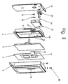
- FIG. 1 shows some components of a display device 1 for an elevator system in the undeveloped state.
- Electroluminescent indicator 2 and a sound reproduction device 3 are escaping with a frame 4 and a housing 5 arranged.
- the electroluminescent indicator as electroluminescent lamp 2 and the Sound reproduction apparatus designed as a flat speaker 3.
- the flat speaker 3 has a panel 3a and an exciter 3b on.
- the electroluminescent lamp 2 is in this Registration also referred to as EL film 2.
- EL film 2 The simplicity for the sake of convenience, the term electroluminescence is used below shortened by the name EL.
- the EL foil 2 and the Flat speakers 3 are with the frame 4 and the housing 5 assembled together.
- the frame 4 points to his outer circumference side projections 7, which in corresponding complementary recesses 8 of the inner Snap the circumference of the housing 5 when the frame 4 and that Housing 5 can be assembled together. This will make one simple snap connection achieved.
- Figure 1 is only a projection 7 and a recess 8 are shown.
- the frame 4 is designed so that it clinks when installed of the flat speaker 3 is prevented.
- FIG. 1 A detail of FIG. 1 is shown in FIG the EL film 2 and the flat speaker 3 indicated in more detail are.
- the EL film 2 has a front or illuminated side 2a and a back or back 2b.
- Front 2a is called the glowing side and on which the letter 6 is legible.
- the flat speaker 3 is thus installed Condition glued to the back 2b of the EL film 2.
- the EL film 2 also has a flexible tab 10 which the electrical connections 11 for control and thus for Illumination of the EL film has.
- Two connections 11 are sufficient to the EL film 2, that is, the EL lamp, for Bring lights.
- the tab 10 is one corresponding groove 10a bent in the flat speaker 3. The Ends of the electrical connections 11 are thus in the installed condition on the back of the Flat speaker 3, that is on the EL film 2 opposite side of the flat speaker 3.
- the EL technology used in the display device according to the invention is based on the principle of Thick film electroluminescence (DSEL).
- the EL film points Thick film EL components.
- the basic structure looks like this: EL pigments (e.g. ZnS: Cu) are placed between two electrodes (anode and cathode) arranged. Electrically speaking, this arrangement is like one Capacitor. The voltage is applied to the electrodes and by exciting the electrons in the EL pigment and their return to the basic state is according to radiation Band model emitted.
- the production of the thick-film EL components can be done using screen printing techniques, which in Comparison with other technologies is relatively simple.
- the structure of layers is typically as follows: starting with the carrier material, a transparent ITO (Indium-tin-oxide) foil, followed by a transparent one conductive layer, then the active layer (consisting of EL pigments in a screen printing matrix), one dielectric non-conductive layer and finally one Silver (or graphite) electrode.
- Typical thicknesses of the Printed layers for DSEL components are in the range 50-60 ⁇ m and typical thicknesses of the entire structure for example between about 200-400 ⁇ m.
- the individual EL pigments can be encapsulated (for example, aluminum hydroxide encapsulation) to this To protect moisture.
- the components already mentioned for the Display device 1 additionally the fixation means shown, by means of which the entire display device 1 a wall 20 or other convenient position of the Lift system is fixed.
- the inner circumference of the frame 4 has projections 12 and a support surface 12a, which for Recording the electronic part 13 are determined.
- the Electronics part is designed as a printed circuit board 13 and is thus on the projections 12 and on the support surface 12a of the Frame 4 attached.
- the EL film 2 and the Flat speakers 3 are together with the frame 4 and the Housing 5 assembled.
- the EL film 2 with the Flat speakers 3 are accommodated in the housing 5.
- the scope of the housing 5 is larger than the scope of the EL foil or the flat speaker 3.
- the frame 4 By the Snap connection of the frame 4 to the housing 5 (the means when installed) that the Back of the speaker 3 on a support surface 4a the frame 4 lies.
- the frame 4 is also in the housing 5th added.
- the ends are of the electrical connections 11 in the installed state between the printed circuit board 13 and a spring element 14.
- the tab 10 is around the speaker 3 and around bent part of the frame 4, the tab 10 through a recess 4b of the frame 4 is made.
- the Spring element 14 By the Spring element 14, the printed circuit board 13 and the electrical connections 11 compressed.
- the printed circuit board 13 and the spring element 14 are by means of a Fastening means 15, for example a screw, on Frame 4 attached.
- the display device 1 further points a wall bracket 16 on the for mounting the Display device 1 on a wall 20 is used.
- On the Wall bracket 16 is by means of further fasteners 18, for example screws, a connector 17 assembled. This connector 17 is designed such that this can be inserted into the printed circuit board 1.
- the Wall bracket 16 is then attached to wall 20.
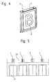
- Figure 4 shows a front view of the assembled Display device 1 from FIG. 1.
- FIG. 5 shows a possible use of the Display device 1 according to the invention in a Elevator system specified.
- the display device 1 is arranged above an elevator door 21 and serves as Label plate for the elevator passengers.
- a raster print can be made on the front / illuminated side 2a of the EL film 2 is provided his.
- the body color of the in the display device 1 used EL film 2 appears in the switched off state light gray. This contrasts with the ones normally used Zinc die-cast housing 5.
- the EL film 2 with a metallic colored grid can be printed.
- the raster print is no longer recognizable is to be printed so that the glow of the EL film is still sufficient mass remains visible.
- the optical effect of a Micro screen printing in front of an EL film around a metallic one Pretending surface can also be for different types Light sources and locations are used.
- the shape of the display device is fundamental no limits. Areas up to several square meters are theoretically possible.
- the display device according to the invention could also have several illuminated fields (service messages).
- the display device can be pixel-like with corresponding Number of connections to be formed.
Landscapes
- Engineering & Computer Science (AREA)
- Mechanical Engineering (AREA)
- Indicating And Signalling Devices For Elevators (AREA)
- Cage And Drive Apparatuses For Elevators (AREA)
Abstract
Description
- akustische Personenführung sehbehinderter Personen zur Liftkabine (Gong, Liftbezeichnung, Türstatus, Servicemeldungen)
- die visuelle Führung von hörbehinderten Personen (blinken)
- Fahrtrichtungsanzeiger und akustische Meldungen auf dem Stockwerk in konventionellen Steuerungen
- Lautsprecher für Kommunikationsschnittstellen und andere akustische Meldungen in Kombination mit einer Notleuchtlampe
- Sprachsysteme mit Signalbeleuchtung in und ausserhalb der Liftkabine
- weitere Führungssysteme mit audio-visueller Unterstützung
- 1
- Anzeigeeinrichtung
- 2
- EL-Anzeiger / EL-Lampe / EL-Folie
- 3
- Tonwiedergabeapparat / Flachlautsprecher
- 3a
- Panel
- 3b
- Erreger
- 4
- Rahmen
- 4a
- Aulagefläche
- 4b
- Aussparung
- 5
- Gehäuse
- 6
- Zeichen / Buchstabe
- 7
- Vorsprung
- 8
- Aussparung
- 9
- Klebstoff
- 10
- Lasche
- 11
- Elektrischer Anschluss
- 12
- Vorsprung
- 12a
- Stützfläche
- 13
- Elektronikteil / Printplatte
- 14
- Federelement
- 15
- Befestigungsmittel / Schraube
- 16
- Wandhalterung
- 17
- Steckverbinder
- 18
- Befestigungsmittel
- 19
- Befestigungsmittel
- 20
- Wand
- 21
- Aufzugstür
Claims (10)
- Anzeigeeinrichtung für eine Aufzugsanlage, wobei die Anzeigeeinrichtung (1) einen Elektrolumineszenz-Anzeiger (2) und einen Tonwiedergabeapparat (3) aufweist,
dadurch gekennzeichnet, dass
der Tonwiedergabeapparat (3) an einer Seite des Elektrolumineszenz-Anzeigers (2) angeordnet ist. - Anzeigeeinrichtung nach Patentanspruch 1,
dadurch gekennzeichnet, dass
der Tonwiedergabeapparat (3) mit dem Elektrolumineszenz-Anzeiger (2) verbunden ist. - Anzeigeeinrichtung nach Patentanspruch 2,
dadurch gekennzeichnet, dass
der Tonwiedergabeapparat (3) mit dem Elektrolumineszenz-Anzeiger (2) mittels eines Klebstoffs (7) verbunden ist. - Anzeigeeinrichtung nach einem der vorhergehenden Patentansprüche,
dadurch gekennzeichnet, dass
der Tonwiedergabeapparat (3) und der Elektrolumineszenz-Anzeiger (2) hintereinander angeordnet sind. - Anzeigeeinrichtung nach einem der vorhergehenden Patentansprüche,
dadurch gekennzeichnet, dass
der Tonwiedergabeapparat (3) und der Elektrolumineszenz-Anzeiger (2) zwischen einem Rahmen (4) und einem Gehäuse (5) angeordnet sind. - Anzeigeeinrichtung nach einem der vorhergehenden Patentansprüche,
dadurch gekennzeichnet, dass
der Tonwiedergabeapparat (3) als Flachlautsprecher ausgebildet ist. - Anzeigeeinrichtung nach einem der vorhergehenden Patentansprüche,
dadurch gekennzeichnet, dass
der Elektrolumineszenz-Anzeiger (2) nach dem Prinzip der Dickschicht-Elektrolumineszenz aufgebaut ist. - Anzeigeeinrichtung nach einem der vorhergehenden Patentansprüche,
dadurch gekennzeichnet, dass
der Elektrolumineszenz-Anzeiger (2) als Elektrolumineszenz-Lampe ausgebildet ist. - Anzeigeeinrichtung nach einem der vorhergehenden Patentansprüche,
dadurch gekennzeichnet, dass die Anzeigeeinrichtung (1) Fixierungsmittel aufweist, sodass die Anzeigeeinrichtung (1) an einer Wand (20) der Aufzugsanlage fixierbar ist. - Anzeigeeinrichtung nach Patentanspruch 9,
dadurch gekennzeichnet, dass
die Fixierungsmittel eine Wandhalterung (16) aufweisen.
Priority Applications (1)
| Application Number | Priority Date | Filing Date | Title |
|---|---|---|---|
| EP20020005798 EP1245520B1 (de) | 2001-03-28 | 2002-03-14 | Anzeigeeinrichtung |
Applications Claiming Priority (3)
| Application Number | Priority Date | Filing Date | Title |
|---|---|---|---|
| EP01810315 | 2001-03-28 | ||
| EP01810315 | 2001-03-28 | ||
| EP20020005798 EP1245520B1 (de) | 2001-03-28 | 2002-03-14 | Anzeigeeinrichtung |
Publications (2)
| Publication Number | Publication Date |
|---|---|
| EP1245520A1 true EP1245520A1 (de) | 2002-10-02 |
| EP1245520B1 EP1245520B1 (de) | 2006-12-20 |
Family
ID=26077360
Family Applications (1)
| Application Number | Title | Priority Date | Filing Date |
|---|---|---|---|
| EP20020005798 Expired - Lifetime EP1245520B1 (de) | 2001-03-28 | 2002-03-14 | Anzeigeeinrichtung |
Country Status (1)
| Country | Link |
|---|---|
| EP (1) | EP1245520B1 (de) |
Cited By (1)
| Publication number | Priority date | Publication date | Assignee | Title |
|---|---|---|---|---|
| CN110255314A (zh) * | 2019-06-24 | 2019-09-20 | 上海贝思特电气有限公司 | 一种电梯显示器 |
Citations (2)
| Publication number | Priority date | Publication date | Assignee | Title |
|---|---|---|---|---|
| EP0403232A2 (de) * | 1989-06-12 | 1990-12-19 | Otis Elevator Company | Elektrolumineszenzanzeigesystem eines Aufzugs |
| US5565661A (en) * | 1991-07-26 | 1996-10-15 | Inventio Ag | Surface mounted indicating element for elevators |
-
2002
- 2002-03-14 EP EP20020005798 patent/EP1245520B1/de not_active Expired - Lifetime
Patent Citations (2)
| Publication number | Priority date | Publication date | Assignee | Title |
|---|---|---|---|---|
| EP0403232A2 (de) * | 1989-06-12 | 1990-12-19 | Otis Elevator Company | Elektrolumineszenzanzeigesystem eines Aufzugs |
| US5565661A (en) * | 1991-07-26 | 1996-10-15 | Inventio Ag | Surface mounted indicating element for elevators |
Cited By (2)
| Publication number | Priority date | Publication date | Assignee | Title |
|---|---|---|---|---|
| CN110255314A (zh) * | 2019-06-24 | 2019-09-20 | 上海贝思特电气有限公司 | 一种电梯显示器 |
| CN110255314B (zh) * | 2019-06-24 | 2021-03-30 | 上海贝思特电气有限公司 | 一种电梯显示器 |
Also Published As
| Publication number | Publication date |
|---|---|
| EP1245520B1 (de) | 2006-12-20 |
Similar Documents
| Publication | Publication Date | Title |
|---|---|---|
| DE3247531C2 (de) | ||
| EP2008291A1 (de) | Elektrisches installationsgerät | |
| EP0900971A1 (de) | Beleuchtungsvorrichtung mit Leuchtdioden aufweisender Glasplatte | |
| DE102014116739A1 (de) | Leuchte umfassend wenigstens ein OLED-Leuchtmittel | |
| US6598711B2 (en) | Indicating device | |
| DE102008021014A1 (de) | Vorrichtung mit einer Mehrschichtplatte sowie Licht emittierenden Dioden | |
| EP1273809A1 (de) | Klemmvorrichtung zum Befestigen von Platten, insbesondere Glasscheiben, inklusive elektrischer Anschlüsse | |
| DE102010014614A1 (de) | Scheibenleuchte | |
| DE20218626U1 (de) | Schild | |
| EP1245520B1 (de) | Anzeigeeinrichtung | |
| EP2650866A2 (de) | Gehäuse zur Aufnahme eines Betriebsgeräts zum Betreiben einer oder mehrerer Lichtquellen | |
| DE3049064C2 (de) | Leuchtendes Hauskennzeichen | |
| DE102004038752B4 (de) | Touch-Sensor-Anordnung und Verwendung einer Touch-Sensor-Anordnung | |
| DE10317467A1 (de) | Postkarte | |
| EP2037723A2 (de) | LED-Kontaktierung | |
| DE9212685U1 (de) | Verbesserter Stehlampendimmer | |
| EP0799406A1 (de) | Anzeigeinstrument | |
| EP0603706A1 (de) | Lichtleitplatten zur Beleuchtung auswechselbarer Informationen | |
| DE202022100048U1 (de) | Sicherheitszeichenleuchte | |
| DE29519101U1 (de) | Elektroinstallationselement | |
| DE102006055407A1 (de) | OLED-Schutzvorrichtung | |
| AT408152B (de) | Selbstleuchtendes informationssymbol mit elektrolumineszenzfolien | |
| DE19533799C2 (de) | Signalleuchte für Fahrzeuge | |
| DE4104481A1 (de) | Einrichtung zur gleichzeitigen schall- und lichteffekt-abstrahlung | |
| DE3047356A1 (de) | Zur aufstellung im freien geeignetes elektrisches geraet, insbesondere sprechstelle fuer eine wechsel-, gegen- oder lautsprechanlage |
Legal Events
| Date | Code | Title | Description |
|---|---|---|---|
| PUAI | Public reference made under article 153(3) epc to a published international application that has entered the european phase |
Free format text: ORIGINAL CODE: 0009012 |
|
| AK | Designated contracting states |
Kind code of ref document: A1 Designated state(s): AT BE CH CY DE DK ES FI FR GB GR IE IT LI LU MC NL PT SE TR |
|
| AX | Request for extension of the european patent |
Free format text: AL;LT;LV;MK;RO;SI |
|
| 17P | Request for examination filed |
Effective date: 20030324 |
|
| AKX | Designation fees paid |
Designated state(s): AT BE CH CY DE DK ES FI FR GB GR IE IT LI LU MC NL PT SE TR |
|
| GRAP | Despatch of communication of intention to grant a patent |
Free format text: ORIGINAL CODE: EPIDOSNIGR1 |
|
| GRAS | Grant fee paid |
Free format text: ORIGINAL CODE: EPIDOSNIGR3 |
|
| GRAA | (expected) grant |
Free format text: ORIGINAL CODE: 0009210 |
|
| AK | Designated contracting states |
Kind code of ref document: B1 Designated state(s): AT BE CH CY DE DK ES FI FR GB GR IE IT LI LU MC NL PT SE TR |
|
| PG25 | Lapsed in a contracting state [announced via postgrant information from national office to epo] |
Ref country code: DK Free format text: LAPSE BECAUSE OF FAILURE TO SUBMIT A TRANSLATION OF THE DESCRIPTION OR TO PAY THE FEE WITHIN THE PRESCRIBED TIME-LIMIT Effective date: 20061220 Ref country code: IE Free format text: LAPSE BECAUSE OF FAILURE TO SUBMIT A TRANSLATION OF THE DESCRIPTION OR TO PAY THE FEE WITHIN THE PRESCRIBED TIME-LIMIT Effective date: 20061220 Ref country code: IT Free format text: LAPSE BECAUSE OF FAILURE TO SUBMIT A TRANSLATION OF THE DESCRIPTION OR TO PAY THE FEE WITHIN THE PRESCRIBED TIME-LIMIT;WARNING: LAPSES OF ITALIAN PATENTS WITH EFFECTIVE DATE BEFORE 2007 MAY HAVE OCCURRED AT ANY TIME BEFORE 2007. THE CORRECT EFFECTIVE DATE MAY BE DIFFERENT FROM THE ONE RECORDED. Effective date: 20061220 Ref country code: FI Free format text: LAPSE BECAUSE OF FAILURE TO SUBMIT A TRANSLATION OF THE DESCRIPTION OR TO PAY THE FEE WITHIN THE PRESCRIBED TIME-LIMIT Effective date: 20061220 Ref country code: NL Free format text: LAPSE BECAUSE OF FAILURE TO SUBMIT A TRANSLATION OF THE DESCRIPTION OR TO PAY THE FEE WITHIN THE PRESCRIBED TIME-LIMIT Effective date: 20061220 |
|
| REG | Reference to a national code |
Ref country code: GB Ref legal event code: FG4D Free format text: NOT ENGLISH |
|
| REG | Reference to a national code |
Ref country code: CH Ref legal event code: EP |
|
| REF | Corresponds to: |
Ref document number: 50208980 Country of ref document: DE Date of ref document: 20070201 Kind code of ref document: P |
|
| REG | Reference to a national code |
Ref country code: IE Ref legal event code: FG4D Free format text: LANGUAGE OF EP DOCUMENT: GERMAN |
|
| GBT | Gb: translation of ep patent filed (gb section 77(6)(a)/1977) |
Effective date: 20070205 |
|
| PG25 | Lapsed in a contracting state [announced via postgrant information from national office to epo] |
Ref country code: SE Free format text: LAPSE BECAUSE OF FAILURE TO SUBMIT A TRANSLATION OF THE DESCRIPTION OR TO PAY THE FEE WITHIN THE PRESCRIBED TIME-LIMIT Effective date: 20070320 |
|
| PG25 | Lapsed in a contracting state [announced via postgrant information from national office to epo] |
Ref country code: ES Free format text: LAPSE BECAUSE OF FAILURE TO SUBMIT A TRANSLATION OF THE DESCRIPTION OR TO PAY THE FEE WITHIN THE PRESCRIBED TIME-LIMIT Effective date: 20070331 |
|
| REG | Reference to a national code |
Ref country code: HK Ref legal event code: GR Ref document number: 1049989 Country of ref document: HK |
|
| PG25 | Lapsed in a contracting state [announced via postgrant information from national office to epo] |
Ref country code: PT Free format text: LAPSE BECAUSE OF FAILURE TO SUBMIT A TRANSLATION OF THE DESCRIPTION OR TO PAY THE FEE WITHIN THE PRESCRIBED TIME-LIMIT Effective date: 20070423 |
|
| ET | Fr: translation filed | ||
| NLV1 | Nl: lapsed or annulled due to failure to fulfill the requirements of art. 29p and 29m of the patents act | ||
| PLBE | No opposition filed within time limit |
Free format text: ORIGINAL CODE: 0009261 |
|
| STAA | Information on the status of an ep patent application or granted ep patent |
Free format text: STATUS: NO OPPOSITION FILED WITHIN TIME LIMIT |
|
| REG | Reference to a national code |
Ref country code: CH Ref legal event code: PL |
|
| 26N | No opposition filed |
Effective date: 20070921 |
|
| PG25 | Lapsed in a contracting state [announced via postgrant information from national office to epo] |
Ref country code: MC Free format text: LAPSE BECAUSE OF NON-PAYMENT OF DUE FEES Effective date: 20070331 |
|
| PG25 | Lapsed in a contracting state [announced via postgrant information from national office to epo] |
Ref country code: CH Free format text: LAPSE BECAUSE OF NON-PAYMENT OF DUE FEES Effective date: 20070331 Ref country code: LI Free format text: LAPSE BECAUSE OF NON-PAYMENT OF DUE FEES Effective date: 20070331 |
|
| PG25 | Lapsed in a contracting state [announced via postgrant information from national office to epo] |
Ref country code: GR Free format text: LAPSE BECAUSE OF FAILURE TO SUBMIT A TRANSLATION OF THE DESCRIPTION OR TO PAY THE FEE WITHIN THE PRESCRIBED TIME-LIMIT Effective date: 20070321 |
|
| PG25 | Lapsed in a contracting state [announced via postgrant information from national office to epo] |
Ref country code: LU Free format text: LAPSE BECAUSE OF NON-PAYMENT OF DUE FEES Effective date: 20070314 Ref country code: CY Free format text: LAPSE BECAUSE OF FAILURE TO SUBMIT A TRANSLATION OF THE DESCRIPTION OR TO PAY THE FEE WITHIN THE PRESCRIBED TIME-LIMIT Effective date: 20061220 |
|
| PG25 | Lapsed in a contracting state [announced via postgrant information from national office to epo] |
Ref country code: TR Free format text: LAPSE BECAUSE OF FAILURE TO SUBMIT A TRANSLATION OF THE DESCRIPTION OR TO PAY THE FEE WITHIN THE PRESCRIBED TIME-LIMIT Effective date: 20061220 |
|
| REG | Reference to a national code |
Ref country code: FR Ref legal event code: PLFP Year of fee payment: 15 |
|
| REG | Reference to a national code |
Ref country code: FR Ref legal event code: PLFP Year of fee payment: 16 |
|
| PGFP | Annual fee paid to national office [announced via postgrant information from national office to epo] |
Ref country code: AT Payment date: 20170322 Year of fee payment: 16 |
|
| REG | Reference to a national code |
Ref country code: FR Ref legal event code: PLFP Year of fee payment: 17 |
|
| REG | Reference to a national code |
Ref country code: AT Ref legal event code: MM01 Ref document number: 348780 Country of ref document: AT Kind code of ref document: T Effective date: 20180314 |
|
| PG25 | Lapsed in a contracting state [announced via postgrant information from national office to epo] |
Ref country code: AT Free format text: LAPSE BECAUSE OF NON-PAYMENT OF DUE FEES Effective date: 20180314 |
|
| PGFP | Annual fee paid to national office [announced via postgrant information from national office to epo] |
Ref country code: GB Payment date: 20200323 Year of fee payment: 19 |
|
| PGFP | Annual fee paid to national office [announced via postgrant information from national office to epo] |
Ref country code: BE Payment date: 20200319 Year of fee payment: 19 |
|
| PGFP | Annual fee paid to national office [announced via postgrant information from national office to epo] |
Ref country code: FR Payment date: 20200319 Year of fee payment: 19 |
|
| PGFP | Annual fee paid to national office [announced via postgrant information from national office to epo] |
Ref country code: DE Payment date: 20210329 Year of fee payment: 20 |
|
| GBPC | Gb: european patent ceased through non-payment of renewal fee |
Effective date: 20210314 |
|
| REG | Reference to a national code |
Ref country code: BE Ref legal event code: MM Effective date: 20210331 |
|
| PG25 | Lapsed in a contracting state [announced via postgrant information from national office to epo] |
Ref country code: FR Free format text: LAPSE BECAUSE OF NON-PAYMENT OF DUE FEES Effective date: 20210331 Ref country code: GB Free format text: LAPSE BECAUSE OF NON-PAYMENT OF DUE FEES Effective date: 20210314 |
|
| REG | Reference to a national code |
Ref country code: DE Ref legal event code: R071 Ref document number: 50208980 Country of ref document: DE |
|
| PG25 | Lapsed in a contracting state [announced via postgrant information from national office to epo] |
Ref country code: BE Free format text: LAPSE BECAUSE OF NON-PAYMENT OF DUE FEES Effective date: 20210331 |