EP1245473A2 - Rear wheel steering apparatus - Google Patents
Rear wheel steering apparatus Download PDFInfo
- Publication number
- EP1245473A2 EP1245473A2 EP02075920A EP02075920A EP1245473A2 EP 1245473 A2 EP1245473 A2 EP 1245473A2 EP 02075920 A EP02075920 A EP 02075920A EP 02075920 A EP02075920 A EP 02075920A EP 1245473 A2 EP1245473 A2 EP 1245473A2
- Authority
- EP
- European Patent Office
- Prior art keywords
- steering
- actuator
- vehicle
- rear wheel
- axle
- Prior art date
- Legal status (The legal status is an assumption and is not a legal conclusion. Google has not performed a legal analysis and makes no representation as to the accuracy of the status listed.)
- Withdrawn
Links
Images


Classifications
-
- B—PERFORMING OPERATIONS; TRANSPORTING
- B62—LAND VEHICLES FOR TRAVELLING OTHERWISE THAN ON RAILS
- B62D—MOTOR VEHICLES; TRAILERS
- B62D5/00—Power-assisted or power-driven steering
- B62D5/04—Power-assisted or power-driven steering electrical, e.g. using an electric servo-motor connected to, or forming part of, the steering gear
- B62D5/0418—Electric motor acting on road wheel carriers
-
- B—PERFORMING OPERATIONS; TRANSPORTING
- B62—LAND VEHICLES FOR TRAVELLING OTHERWISE THAN ON RAILS
- B62D—MOTOR VEHICLES; TRAILERS
- B62D7/00—Steering linkage; Stub axles or their mountings
- B62D7/06—Steering linkage; Stub axles or their mountings for individually-pivoted wheels, e.g. on king-pins
- B62D7/14—Steering linkage; Stub axles or their mountings for individually-pivoted wheels, e.g. on king-pins the pivotal axes being situated in more than one plane transverse to the longitudinal centre line of the vehicle, e.g. all-wheel steering
- B62D7/15—Steering linkage; Stub axles or their mountings for individually-pivoted wheels, e.g. on king-pins the pivotal axes being situated in more than one plane transverse to the longitudinal centre line of the vehicle, e.g. all-wheel steering characterised by means varying the ratio between the steering angles of the steered wheels
- B62D7/1581—Steering linkage; Stub axles or their mountings for individually-pivoted wheels, e.g. on king-pins the pivotal axes being situated in more than one plane transverse to the longitudinal centre line of the vehicle, e.g. all-wheel steering characterised by means varying the ratio between the steering angles of the steered wheels characterised by comprising an electrical interconnecting system between the steering control means of the different axles
-
- B—PERFORMING OPERATIONS; TRANSPORTING
- B60—VEHICLES IN GENERAL
- B60G—VEHICLE SUSPENSION ARRANGEMENTS
- B60G2200/00—Indexing codes relating to suspension types
- B60G2200/30—Rigid axle suspensions
- B60G2200/314—Rigid axle suspensions with longitudinally arranged arms articulated on the axle
-
- B—PERFORMING OPERATIONS; TRANSPORTING
- B60—VEHICLES IN GENERAL
- B60G—VEHICLE SUSPENSION ARRANGEMENTS
- B60G2200/00—Indexing codes relating to suspension types
- B60G2200/40—Indexing codes relating to the wheels in the suspensions
- B60G2200/44—Indexing codes relating to the wheels in the suspensions steerable
Definitions
- This invention relates generally to an apparatus for steering the rear wheels of a vehicle.
- rear-wheel steering systems are designed to augment the vehicle steering function that conventional front-wheel steering systems provide.
- Some rear-wheel steering systems include multi-link solid axle suspensions having track bars or "pan-hard rods" that pivotally connect a vehicle frame to the axle to minimize ride steer caused by relative vertical motion between a vehicle frame and the axle.
- United States Patent Number 5,820,147 issued 13 October 1998 to Rohentrée et al. discloses a rear wheel steering apparatus including a vehicle frame and a multi-link suspension including a live solid axle and a track bar or pan hard rod connected between the axle and the vehicle frame and a pair of road wheels supported at respective opposite ends of the axle by first and second steering knuckles, the knuckles supporting the road wheels for rotation about respective generally horizontal road wheel rotational axes and for pivotal motion about respective generally vertical steering axes.
- the rear wheel steering apparatus disclosed in the Rohnies et al. patent also includes a steering gear having a pitman arm connected to a second end of the drag link and configured to pivot the roadwheels about their respective pivot axes by alternately pushing and pulling on the drag link.
- a rear wheel steering apparatus constructed according to the Rohnies et al. patent requires a primary connection to a handwheel and thus is not readily adaptable to steering rear road wheels that are remote from the vehicle handwheel.
- United States Patent Number 5,899,292 issued 4 May 1999 to Paul et al. discloses a hydraulic drive and steering system for a vehicle that includes rear road wheel steering arms extending from respective steering knuckles and two linear actuators connected between a frame of the vehicle and respective outer ends of the steering arms to allow an operator to steer the rear road wheels using a handwheel without a primary connection between the handwheel and the rear road wheels.
- a rear wheel steering apparatus constructed according to the Paul et al. patent cannot be incorporated into existing multi-link suspension systems without changing existing suspension geometry.
- the prior art also includes a front wheel drive system 10 having a solid axle 11 and including a linear power steering actuator 12 that connects to a drag link 14.
- the drag link 14 connects to a pair of steering arms 16 extending from a pair of steering knuckles 18. Extension and retraction of the power steering actuator 12 alternately pushes and pulls on the drag link 14 resulting in steering inputs to a pair of front road wheels 20 connected to the steering knuckles.
- the system relies on a primary connection to a hand wheel input and would be difficult to adapt for use in steering rear wheels mounted remote from the hand wheel input on a live rear axle of a vehicle in a multi-link suspension.
- a steering apparatus that can steer road wheels mounted on a rear axle of a vehicle without requiring a primary connection to the handwheel.
- a rear wheel steering apparatus that can be incorporated into existing multi-link suspension designs without changing existing suspension geometry.
- a rear wheel steering apparatus for steering the rear wheels of a vehicle includes a multi-link suspension including a live axle and a track bar pivotally connecting the axle to a vehicle frame.
- First and second steering knuckles are supported at respective opposite ends of the axle and are configured to support respective road wheels for rotation about respective generally horizontal road wheel rotational axes and for pivotal motion about respective generally vertical steering axes.
- the rear wheel steering apparatus also includes first and second steering arms that extend generally horizontally from the respective first and second steering knuckles in a direction generally perpendicular to the respective steering axes.
- a drag link extends between and interconnects respective outer ends of the steering arms, the ends of the arms being spaced from the respective steering knuckles.
- the rear wheel steering apparatus also includes an actuator having a first end connected to the frame and a second end connected to the drag link.
- the actuator is positioned and configured to pivot the roadwheels about their respective steering axes by alternately pushing and pulling on the drag link. Therefore, a rear wheel steering apparatus constructed according to the invention is able to steer road wheels mounted on a rear axle of the vehicle that is remote from the vehicle handwheel without requiring a primary connection to the handwheel.
- the apparatus may be readily incorporated into existing multi-link suspension designs without changing existing suspension geometry.
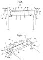
- FIGS. 2-6 An apparatus for steering the rear wheels 40 of vehicle is generally indicated at 30, in FIGS. 2-6.
- the apparatus 30 is shown installed in a multi-link suspension system generally indicated at 32 in FIGS. 2-6.
- the multi-link suspension system 32 includes a live solid axle 34 and a track bar, or "pan-hard rod" 36.
- the track bar 36 pivotally connects the axle 34 to a vehicle frame 37.
- the axle 34 need not be a solid axle.
- the steering apparatus 30 includes left and right steering knuckles 38, 39 supported at respective opposite ends of the axle 34.
- the steering knuckles 38, 39 are configured to support respective road wheels 40 for rotation about respective left and right generally horizontal road wheel rotational axes 42, 44.
- the steering knuckles 38 also support the road wheels 40 for pivotal motion about respective left and right generally vertical steering axes 46, 48.
- Left and right steering arms 47, 49 extend generally horizontally from the respective left and right steering knuckles 38 in respective directions generally perpendicular to the respective road wheel steering axes 46, 48.
- a drag link 50 extends between and interconnects respective outer ends of the steering arms 47, 49.
- the outer ends of the steering arms 47, 49 are spaced from the respective steering knuckles 38, 39 to provide the drag link 50 with a mechanical advantage sufficient to rotate the road wheels and steering knuckles 38, 39 about the steering axes 46, 48.
- the steering apparatus 30 also includes an electric double-acting linear actuator shown at 52 in FIGS 2-6.
- the linear actuator 52 has a first end 54 connected to the frame 37 and a second end 56 connected to the drag link 50.
- the actuator 52 is positioned and configured to pivot the rear road wheels 40 about their respective steering axes 46, 48 by alternately pushing and pulling on the drag link 50.
- the linear actuator 52 may comprise any suitable linear actuator known in the art such as a double-acting hydraulic cylinder.
- a controller would control the cylinder by operating a hydraulic valve connected to the cylinder.
- the body origin or first end 54 of the linear actuator 52 is connected to the frame 37 at an actuator-frame connection point 56 disposed adjacent a track bar-frame connection point 58.
- the actuator-frame and track bar-frame connection points 56, 58 are disposed adjacent one another to minimize steering feedback, i.e., uncommanded steering inputs caused by relative motion between the frame 37 and the axle 34.
- the linear actuator 52 is mounted in a position that allows it to operate in parallel with the track bar 36.
- the actuator 52 and track bar 36 have the same approximate length.
- the linear distance from the actuator-frame connection point to a actuator 52-drag link 50 connection point is generally equal to the linear distance from the track bar-frame mounting point to a track bar 36-axle 34 mounting point.
- the track bar 36 causes the axle 34 to follow a radius established by the track bar 36 when the axle 34 travels up and down relative to the frame 37. Because the dynamic connection points of the actuator 52 and track bar 36 remain relatively close to one another and the respective linear distances between actuator 52 and track bar 36 mounting points are equal or nearly so, the actuator 52 is not in a position to convert relative vertical motion between the axle 34 and the frame 37 into rear wheel steering inputs of any appreciable magnitude. In other words, the vertical motion of the axle 34 relative to the frame 37 cannot cause significant extension or retraction in the actuator 52 when the actuator 52 is in the straight-ahead position.
- the actuator 52 and track bar 36 are configured and positioned such that respective linear distances between actuator 52 and track bar 36 mounting points are not equal when the actuator 52 is either extended or retracted out of the straight-ahead steering position to angulate the rear road wheels 40.
- the length of the actuator 52 changes from that of the track bar 36 when the rear wheels 40 are angulated.
- This difference in lengths between the actuator 52 and the track bar 36 can result in small steering angle errors when the axle 34 moves up and down relative to the frame 37.
- the resulting amount of steering angle error is small because the difference between the linear distances is small compared to the length of the track bar 36, the vertical travel of the axle 34 from it nominal ride height and the length of steering arms 47, 49.
- the steering apparatus 30 includes an electronic controller 60 and a hand wheel position sensor 62 connected to the controller 60.
- the electronic controller 60 is configured to sense hand wheel steering inputs transmitted by the hand wheel position sensor 62.
- the controller 60 is connected to the actuator 52 and is programmed to send control signals to the actuator 52 to extend and contract the actuator 52 in response to signal inputs from the hand wheel position sensor 62.
- the apparatus 30 also includes a vehicle speed sensor shown at 64 in FIG. 7.
- the vehicle speed sensor 64 is connected to the controller 60 and is configured to sense vehicle speed and provide a corresponding output signal to the controller 60.
- the controller 60 is configured to modify controlling inputs to the actuator 52 in response to signal inputs from the vehicle speed sensor 64. As it is explained more fully below, the controller 60 changes the amount of actuator deflection in proportion to the speed of the vehicle.
- the apparatus 30 also includes a front wheel angle sensor 66 that is connected to the controller 60 and senses respective steering angles or angulation of front wheels 40 of the vehicle.
- the angulation or steering angle of a wheel is the angular measure of the rotation of a wheel around its generally vertical steering axis as measured from a position in which the wheel is orientated perpendicular to the axle 34 it is supported on.
- the controller 60 is configured to modify control signals to the actuator 52 in response to signal inputs from the front wheel angle sensor 64. As is more fully described below, the controller 60 will not allow the rear wheel angulation to exceed a predetermined percentage of concurrent front wheel angulation.
- the controller 60 angulates the rear road wheels 40 by an amount that decreases as the speed of the vehicle increases. In other words, the controller allows the rear wheels 40 turn less at high speed and more at low speed. This inverse relationship reduces steering sensitivity at high speed and increases steering sensitivity at a low speed.
- the controller 60 commands the actuator 52 to steer the rear road wheels 40 out of phase with the front road wheels 40, i.e., opposite the direction of the front road wheels 40, when the vehicle is traveling at less than a predetermined speed. This causes the rear road wheels 40 to follow the arcuate track of the respective front wheels 40 rather than "cutting the corner" as they would do if they were either unsteered or steered in phase.
- the controller 60 limits rear wheel steering to a maximum of one-half the concurrent steering angle of the front wheels 40. Because front wheel steering angles normally do not exceed two degrees at high speed, rear wheel steering is normally limited to a maximum of one degree at high speed. Therefore, even if the rear axle 34 were to experience significant vertical deflection during a lane change at high speed, the resulting uncommanded steering input or feedback transmitted to the hand wheel, would be minute. The resulting uncommanded steering input would be minute both because the actuator 52 and track bar 36 dynamic connection points are either co-located or are very close together and because the controller 60 will cut in half what ever small amount of deflection occurs. At very low speeds, movements of the axle 34 are much slower and less severe and the controller 60 commands the actuator 52 to turn the rear wheels 40 out of phase. Therefore, at low speeds, even when the rear steering angle is at its maximum, any uncommanded steering inputs will pose no threat to directional stability or occupant safety.
- the steering apparatus 30 also includes a vehicle attitude sensor such as a ride height or yaw sensor 68 that is supported in the vehicle and is connected to the controller 60.
- vehicle attitude sensor 68 is positioned on a "sprung" portion of the vehicle such as the vehicle frame to detect vehicle attitude changes that are known to cause uncommanded steering inputs by changing actuator 52 length through frame 37 movement relative to the axle 34 and drag link 50.
- the controller 60 receives vehicle attitude signals from the vehicle attitude sensor 68 and, in response, commands changes in actuator length to eliminate the uncommanded steering inputs that the vehicle attitude changes would otherwise have caused.
- the body origin 54 of the actuator 52 of the steering apparatus 30 is mounted to the frame 37, the mass of the axle 34 is lower than it would be if the actuator 52 where mounted to the axle 34 as in some prior art systems.
- the steering apparatus 30 described above may be incorporated into the multi-link rear suspension of a motor vehicle without modifying existing suspension geometry. By simply adding steering knuckles 38 with steering arms 47, 49 connected by a drag link 50 and by installing a linear actuator 52 between the frame 37 and drag link 50. The installation can be accomplished regardless of axle configuration or size. The cost and complexity of the steering apparatus 30 is minimized because its design is not dependent on the configuration of any particular multi-link suspension system.
Landscapes
- Engineering & Computer Science (AREA)
- Chemical & Material Sciences (AREA)
- Combustion & Propulsion (AREA)
- Transportation (AREA)
- Mechanical Engineering (AREA)
- Steering-Linkage Mechanisms And Four-Wheel Steering (AREA)
- Steering Control In Accordance With Driving Conditions (AREA)
- Vehicle Body Suspensions (AREA)
Abstract
Description
Claims (16)
- An apparatus (30) for steering the rear wheels (40) of a vehicle, the apparatus (30) comprising:a multi-link suspension (32) including an axle (34) and a track bar (36) pivotally connecting the axle (34) to a vehicle frame (37);first and second steering knuckles (38, 39) supported at respective opposite ends of the axle (34) and configured to support respective road wheels (40) for rotation about respective generally horizontal road wheel rotational axes (42, 44) and for pivotal motion about respective generally vertical steering axes (46, 48);first and second steering arms (47, 49) extending generally horizontally from the respective first and second steering knuckles (38, 39) in a direction generally perpendicular to the respective steering axes (46, 48);a drag link (50) extending between and interconnecting respective outer ends of the steering arms (47, 49) spaced from the respective steering knuckles (38, 39); andan actuator (52) having a first end (54) connected to the frame (37) and a second end (56) connected to the drag link (50), the actuator (52) positioned and configured to pivot the roadwheels about their respective steering axes (46, 48) by alternately pushing and pulling on the drag link (50).
- A rear wheel steering apparatus (30) as defined in claim 1 in which the actuator (52) is connected in parallel with the track bar (36), a first end (54) of the actuator (52) being connected to the frame (37) at an actuator-frame connection point (56) disposed adjacent a track bar-frame connection point (58).
- A rear wheel steering apparatus (30) as defined in claim 1 in which the actuator (52) is a double-acting linear actuator.
- A rear wheel steering apparatus (30) as defined in claim 1 and further including:a controller (60) connected to the actuator (52); anda handwheel position sensor (62) connected to the controller (60) and configured to sense handwheel steering inputs, the controller (60) being configured to control the actuator (52) to move the drag link (50) in response to signal inputs from the handwheel position sensor (62).
- A rear wheel steering apparatus (30) as defined in claim 4 and further including a vehicle speed sensor (64) connected to the controller (60) and configured to sense vehicle speed, the controller (60) configured to control the actuator (52) to move the drag link (50) in response to signal inputs from the vehicle speed sensor (64).
- A rear wheel steering apparatus (30) as defined in claim 4 and further including a front wheel angle sensor (66) connected to the controller (60) and configured to sense respective steering angles of front wheels of the vehicle, the controller (60) configured to control the actuator (52) to move the drag link (50) in response to signal inputs from the front wheel angle sensor (66).
- A rear wheel steering apparatus (30) as defined in claim 3 in which a first end (54) of the linear actuator (52) is a body origin (54) of the actuator (52).
- A rear wheel steering apparatus (30) as defined in claim 3 in which the linear actuator (52) is configured and positioned to operate in parallel with the track bar (36).
- A rear wheel steering apparatus (30) as defined in claim 3 in which respective frame connection points (56, 58) of the actuator (52) and track bar (36) are at the same approximate point.
- A rear wheel steering apparatus (30) as defined in claim 3 in which the actuator (52) and track bar (36) are configured and positioned such that when the drag link (50) and steering bars are in a position that does not angulate the rear wheels (40), the linear distance from the actuator (52)-frame (37) connection point to an actuator (52)-drag link (50) connection point is generally equal to the linear distance from the track bar-frame mounting point to a track bar-axle mounting point.
- A rear wheel steering apparatus (30) as defined in claim 10 in which the actuator (52) and track bar (36) are configured and positioned such that inequalities in the respective linear distances between actuator (52) and track bar (36) mounting points are small enough compared to track bar (36) length, vertical axle (34) travel and steering arm length, to preclude significant uncommanded steering inputs.
- A rear wheel steering apparatus (30) as defined in claim 4 in which the controller (60) is configured to angulate the rear road wheels (40) by an amount that decreases as the speed of the vehicle increases.
- A rear wheel steering apparatus (30) as defined in claim 4 in which the controller (60) is configured to steer the rear road wheels (40) out of phase with the front road wheels (40) when the vehicle is traveling at less than a predetermined speed.
- A rear wheel steering apparatus (30) as defined in claim 4 in which the controller (60) is configured to limit rear wheel steering to a maximum of half the steering angle of the front wheels.
- A rear wheel steering apparatus (30) as defined in claim 4 in which a vehicle attitude sensor (68) is supported in the vehicle, is connected to the controller (60) and is configured and positioned to detect vehicle attitude changes, the controller (60) being configured to receive vehicle attitude signals from the vehicle attitude sensor (68) and to command changes in actuator (52) length to counter uncommanded steering inputs that the vehicle attitude changes would otherwise have caused.
- An apparatus (30) for steering the wheels of a vehicle having a multi-link suspension (32) including an axle (34) and a track bar (36) pivotally connecting the axle (34) to a vehicle frame (37), the apparatus (30) comprising:first and second steering knuckles (38, 39) supported at respective opposite ends of the axle (34) and configured to support respective road wheels (40) for rotation about respective generally horizontal road wheel rotational axes (42, 44) and for pivotal motion about respective generally vertical steering axes (46, 48);first and second steering arms (47, 49) extending generally horizontally from the respective first and second steering knuckles (38, 39) in a direction generally perpendicular to the respective steering axes (46, 48);a drag link (50) extending between and interconnecting respective outer ends of the steering arms (47, 49) spaced from the respective steering knuckles (38, 39);an actuator (52) having a second end (56) connected to the drag link (50) and configured to pivot the roadwheels by alternately pushing and pulling on the drag link (50); and characterized by:the actuator (52) being connected in parallel with the track bar (36) with a first end (54) of the actuator (52) connected to the vehicle frame (37) to reduce the weight of the axle (34) and to minimize ride steer.
Applications Claiming Priority (2)
| Application Number | Priority Date | Filing Date | Title |
|---|---|---|---|
| US819502 | 2001-03-28 | ||
| US09/819,502 US6510917B2 (en) | 2001-03-28 | 2001-03-28 | Rear wheel steering apparatus |
Publications (2)
| Publication Number | Publication Date |
|---|---|
| EP1245473A2 true EP1245473A2 (en) | 2002-10-02 |
| EP1245473A3 EP1245473A3 (en) | 2003-09-24 |
Family
ID=25228341
Family Applications (1)
| Application Number | Title | Priority Date | Filing Date |
|---|---|---|---|
| EP02075920A Withdrawn EP1245473A3 (en) | 2001-03-28 | 2002-03-08 | Rear wheel steering apparatus |
Country Status (3)
| Country | Link |
|---|---|
| US (1) | US6510917B2 (en) |
| EP (1) | EP1245473A3 (en) |
| JP (1) | JP2002326578A (en) |
Cited By (4)
| Publication number | Priority date | Publication date | Assignee | Title |
|---|---|---|---|---|
| FR2862937A1 (en) * | 2003-12-02 | 2005-06-03 | Renault Sas | AXLE FOR A MOTOR VEHICLE AND ACTUATOR OF SUCH A AXLE |
| WO2009155911A1 (en) * | 2008-06-25 | 2009-12-30 | Zf Friedrichshafen Ag | Twist-beam rear axle |
| CN107351913A (en) * | 2017-07-17 | 2017-11-17 | 聊城中通轻型客车有限公司 | A kind of trailing wheel active steering apparatus |
| DE102021132621A1 (en) | 2021-12-10 | 2022-10-13 | Schaeffler Technologies AG & Co. KG | Sensor assembly, steering actuator and method of operating a sensor assembly |
Families Citing this family (20)
| Publication number | Priority date | Publication date | Assignee | Title |
|---|---|---|---|---|
| US6801125B1 (en) * | 2003-03-19 | 2004-10-05 | Delphi Technologies, Inc. | Rear steering hitch/docking mode |
| DE10338998A1 (en) * | 2003-08-25 | 2005-03-24 | Trw Fahrwerksysteme Gmbh & Co. Kg | Vehicle steering system with steering link or tie rod moveable perpendicular to direction of adjustment of the steering gear |
| US7077234B2 (en) * | 2003-10-03 | 2006-07-18 | Daimlerchrysler Corporation | Rack and pinion steering assembly |
| US7300064B2 (en) * | 2005-03-17 | 2007-11-27 | Chrysler Llc | Lateral control mechanism for an axle beam suspension system |
| US7854293B2 (en) * | 2007-02-20 | 2010-12-21 | Textron Innovations Inc. | Steering operated by linear electric device |
| WO2009046246A1 (en) * | 2007-10-04 | 2009-04-09 | Oshkosh Corporation | Vehicle steering system |
| US8733771B2 (en) * | 2011-12-19 | 2014-05-27 | Chrysler Group Llc | Vehicle suspension system |
| DE102013208539B4 (en) | 2013-05-08 | 2023-07-27 | Wirtgen Gmbh | Device for preparing road or ground surfaces |
| DE102013208484B4 (en) | 2013-05-08 | 2018-04-26 | Wirtgen Gmbh | Device for processing road or ground surfaces, and method for steering a road milling machine |
| KR101619642B1 (en) | 2014-11-17 | 2016-05-10 | 현대자동차주식회사 | Method steering wheel using drag link |
| DE102015202994A1 (en) | 2015-02-19 | 2016-08-25 | Ford Global Technologies, Llc | Control of a rear axle frame |
| US10099530B2 (en) * | 2016-08-23 | 2018-10-16 | Matthew Ethan Grimes | Vehicle suspension pan hard bar (track bar) tensioning and damping technique |
| JP6834662B2 (en) * | 2017-03-24 | 2021-02-24 | アイシン精機株式会社 | vehicle |
| US11083973B2 (en) * | 2017-11-09 | 2021-08-10 | Namero, LLC | Vehicle hopping system |
| US10814905B2 (en) * | 2018-05-21 | 2020-10-27 | Ford Global Technologies, Llc | Electric power assisted steering systems for solid axle front suspension vehicles |
| US10836424B2 (en) | 2018-06-06 | 2020-11-17 | Ford Global Technologies, Llc | Wheel steering apparatus to generate positive rear Ackermann |
| US10822028B2 (en) | 2018-10-03 | 2020-11-03 | Ford Global Technologies, Llc | Steering system with drag link |
| TR202000792A1 (en) * | 2020-01-20 | 2021-07-26 | Hema Enduestri A S | A STEERING SYSTEM |
| US11827073B2 (en) * | 2020-12-21 | 2023-11-28 | Oshkosh Corporation | Four bar linkage and air spring suspension system |
| CN115535017B (en) * | 2021-06-30 | 2024-09-10 | 比亚迪股份有限公司 | Bogie of rail vehicle and rail vehicle |
Family Cites Families (22)
| Publication number | Priority date | Publication date | Assignee | Title |
|---|---|---|---|---|
| US2507106A (en) * | 1946-02-28 | 1950-05-09 | Roland W Knapp | Hydraulic steering gear for motor vehicles |
| US2826258A (en) * | 1955-08-31 | 1958-03-11 | Bendix Aviat Corp | Valve and valve-actuating mechanism for hydraulic steering system |
| US3527316A (en) * | 1968-11-19 | 1970-09-08 | Allis Chalmers Mfg Co | Steering mechanism |
| US3763951A (en) * | 1971-06-07 | 1973-10-09 | Sycon Corp | Vehicle power steering system |
| US3814203A (en) * | 1973-01-22 | 1974-06-04 | C Gieszl | Steering system |
| GB1529302A (en) * | 1974-10-05 | 1978-10-18 | Coles Cranes Ltd | Steering arrangements for mobile cranes |
| US4359123A (en) * | 1979-09-06 | 1982-11-16 | Allis-Chalmers Corporation | Adjustable power steering mechanism |
| JPS5923716A (en) * | 1982-07-31 | 1984-02-07 | Isuzu Motors Ltd | Controller for alignment of rear wheel |
| US4475615A (en) * | 1982-08-16 | 1984-10-09 | Massey-Ferguson Inc. | Power steering system |
| US4970646A (en) * | 1987-11-12 | 1990-11-13 | Nissan Motor Co., Ltd. | Vehicle having secondarily steered front and rear wheels |
| DE4118699C2 (en) * | 1991-06-07 | 1994-03-31 | Bosch Gmbh Robert | Steering system |
| US5734570A (en) * | 1992-08-04 | 1998-03-31 | Lotus Cars Limited | Wheeled vehicle steering system for steering the rear wheels of a vehicle |
| JP2864962B2 (en) * | 1993-08-10 | 1999-03-08 | 三菱自動車工業株式会社 | Rear wheel steering device |
| KR950017622A (en) * | 1993-12-14 | 1995-07-20 | 전성원 | 4-wheel steering system |
| US5427195A (en) | 1994-05-04 | 1995-06-27 | Int. Silvatech Ltd. | Hydraulic drive and steering systems for a vehicle |
| KR0184435B1 (en) * | 1996-07-11 | 1999-04-01 | 김영귀 | Method of controlling the angle of a rear wheel of 4-wheel steering system |
| JP3493568B2 (en) * | 1997-02-12 | 2004-02-03 | 光洋精工株式会社 | Car steering system |
| US5820147A (en) | 1997-03-31 | 1998-10-13 | Ford Global Technologies, Inc. | Steerable solid axle suspension for a vehicle |
| US5884925A (en) * | 1998-03-17 | 1999-03-23 | General Motors Corporation | Solid axle suspension for vehicles |
| US6267395B1 (en) * | 1999-10-18 | 2001-07-31 | Durrell U. Howard | Vehicle steering compensator with air actuated trim mechanism |
| US6267198B1 (en) * | 1999-12-23 | 2001-07-31 | New Holland North America, Inc. | Offset kingpin for a rear steering axle on an agricultural combine |
| US6357768B1 (en) * | 2000-09-19 | 2002-03-19 | General Motors Corporation | Straight line linkage mechanism |
-
2001
- 2001-03-28 US US09/819,502 patent/US6510917B2/en not_active Expired - Fee Related
-
2002
- 2002-03-08 EP EP02075920A patent/EP1245473A3/en not_active Withdrawn
- 2002-03-28 JP JP2002091826A patent/JP2002326578A/en active Pending
Cited By (6)
| Publication number | Priority date | Publication date | Assignee | Title |
|---|---|---|---|---|
| FR2862937A1 (en) * | 2003-12-02 | 2005-06-03 | Renault Sas | AXLE FOR A MOTOR VEHICLE AND ACTUATOR OF SUCH A AXLE |
| EP1538067A1 (en) * | 2003-12-02 | 2005-06-08 | Renault | Vehicle axle and actuator for said axle |
| WO2009155911A1 (en) * | 2008-06-25 | 2009-12-30 | Zf Friedrichshafen Ag | Twist-beam rear axle |
| CN107351913A (en) * | 2017-07-17 | 2017-11-17 | 聊城中通轻型客车有限公司 | A kind of trailing wheel active steering apparatus |
| CN107351913B (en) * | 2017-07-17 | 2023-09-05 | 中通客车股份有限公司 | Active steering device for rear wheel |
| DE102021132621A1 (en) | 2021-12-10 | 2022-10-13 | Schaeffler Technologies AG & Co. KG | Sensor assembly, steering actuator and method of operating a sensor assembly |
Also Published As
| Publication number | Publication date |
|---|---|
| US20020140198A1 (en) | 2002-10-03 |
| US6510917B2 (en) | 2003-01-28 |
| JP2002326578A (en) | 2002-11-12 |
| EP1245473A3 (en) | 2003-09-24 |
Similar Documents
| Publication | Publication Date | Title |
|---|---|---|
| US6510917B2 (en) | Rear wheel steering apparatus | |
| EP0246116B1 (en) | Camber control system for a motor vehicle | |
| EP3568308B1 (en) | Vehicle suspension system | |
| US5415427A (en) | Wheel suspension system | |
| US5286052A (en) | Vehicle suspension with floating upper arm | |
| WO2001087689A1 (en) | Tilting vehicle provided with steerable rear wheels | |
| EP3984862B1 (en) | Motor-vehicle with driving and steering rear wheels | |
| CA2013570C (en) | Four-wheel steerable vehicle having a fore/aft sliding link | |
| US5116076A (en) | Wheel suspension system for steerable rear wheels of motor vehicles | |
| CN113859353A (en) | Wheel steering device | |
| US6561307B1 (en) | Independent suspension steering system | |
| JPH10310071A (en) | Rack-and-pinion type steering system for four-wheel drive vehicle | |
| GB2347398A (en) | Vehicle suspensions | |
| EP0323414B1 (en) | Rear suspension for motor vehicles, of the type with independent wheels and longitudinal arms | |
| KR910006830B1 (en) | Anti-roll Mechanism by Castor Control | |
| EP0785124B1 (en) | Compound steering mechanism | |
| WO1989001436A1 (en) | A method of controlling a transport means and a transport means for effecting the method | |
| US20250108868A1 (en) | Trailer steering system | |
| EP0905006A2 (en) | A device for controlling the steering angle in trucks or articulated trucks | |
| EP0661183B1 (en) | A suspension for a vehicle steered wheel adopting a multiple-rod arrangement | |
| CN2531992Y (en) | Bidirectional inclained angle changeable steering knuckle | |
| GB2298693A (en) | A linear-motion Watts linkage for a vehicle suspension | |
| GB2177054A (en) | Vehicle steering | |
| US4928984A (en) | Steering system for tracking of wheels | |
| JPH0899517A (en) | Vehicle rear wheel suspension |
Legal Events
| Date | Code | Title | Description |
|---|---|---|---|
| PUAI | Public reference made under article 153(3) epc to a published international application that has entered the european phase |
Free format text: ORIGINAL CODE: 0009012 |
|
| AK | Designated contracting states |
Kind code of ref document: A2 Designated state(s): AT BE CH CY DE DK ES FI FR GB GR IE IT LI LU MC NL PT SE TR |
|
| AX | Request for extension of the european patent |
Free format text: AL;LT;LV;MK;RO;SI |
|
| PUAL | Search report despatched |
Free format text: ORIGINAL CODE: 0009013 |
|
| AK | Designated contracting states |
Kind code of ref document: A3 Designated state(s): AT BE CH CY DE DK ES FI FR GB GR IE IT LI LU MC NL PT SE TR |
|
| AX | Request for extension of the european patent |
Extension state: AL LT LV MK RO SI |
|
| AKX | Designation fees paid | ||
| REG | Reference to a national code |
Ref country code: DE Ref legal event code: 8566 |
|
| STAA | Information on the status of an ep patent application or granted ep patent |
Free format text: STATUS: THE APPLICATION IS DEEMED TO BE WITHDRAWN |
|
| 18D | Application deemed to be withdrawn |
Effective date: 20040325 |