EP1245411A2 - Method of making finite element model of tire having at least one fine groove - Google Patents
Method of making finite element model of tire having at least one fine groove Download PDFInfo
- Publication number
- EP1245411A2 EP1245411A2 EP02007026A EP02007026A EP1245411A2 EP 1245411 A2 EP1245411 A2 EP 1245411A2 EP 02007026 A EP02007026 A EP 02007026A EP 02007026 A EP02007026 A EP 02007026A EP 1245411 A2 EP1245411 A2 EP 1245411A2
- Authority
- EP
- European Patent Office
- Prior art keywords
- nodes
- elements
- tire
- fine groove
- boundary face
- Prior art date
- Legal status (The legal status is an assumption and is not a legal conclusion. Google has not performed a legal analysis and makes no representation as to the accuracy of the status listed.)
- Granted
Links
Images


Classifications
-
- B—PERFORMING OPERATIONS; TRANSPORTING
- B60—VEHICLES IN GENERAL
- B60C—VEHICLE TYRES; TYRE INFLATION; TYRE CHANGING; CONNECTING VALVES TO INFLATABLE ELASTIC BODIES IN GENERAL; DEVICES OR ARRANGEMENTS RELATED TO TYRES
- B60C11/00—Tyre tread bands; Tread patterns; Anti-skid inserts
-
- B—PERFORMING OPERATIONS; TRANSPORTING
- B60—VEHICLES IN GENERAL
- B60C—VEHICLE TYRES; TYRE INFLATION; TYRE CHANGING; CONNECTING VALVES TO INFLATABLE ELASTIC BODIES IN GENERAL; DEVICES OR ARRANGEMENTS RELATED TO TYRES
- B60C11/00—Tyre tread bands; Tread patterns; Anti-skid inserts
- B60C11/03—Tread patterns
- B60C11/11—Tread patterns in which the raised area of the pattern consists only of isolated elements, e.g. blocks
-
- B—PERFORMING OPERATIONS; TRANSPORTING
- B60—VEHICLES IN GENERAL
- B60C—VEHICLE TYRES; TYRE INFLATION; TYRE CHANGING; CONNECTING VALVES TO INFLATABLE ELASTIC BODIES IN GENERAL; DEVICES OR ARRANGEMENTS RELATED TO TYRES
- B60C11/00—Tyre tread bands; Tread patterns; Anti-skid inserts
- B60C11/03—Tread patterns
- B60C11/12—Tread patterns characterised by the use of narrow slits or incisions, e.g. sipes
-
- B—PERFORMING OPERATIONS; TRANSPORTING
- B60—VEHICLES IN GENERAL
- B60C—VEHICLE TYRES; TYRE INFLATION; TYRE CHANGING; CONNECTING VALVES TO INFLATABLE ELASTIC BODIES IN GENERAL; DEVICES OR ARRANGEMENTS RELATED TO TYRES
- B60C99/00—Subject matter not provided for in other groups of this subclass
- B60C99/006—Computer aided tyre design or simulation
-
- G—PHYSICS
- G06—COMPUTING OR CALCULATING; COUNTING
- G06F—ELECTRIC DIGITAL DATA PROCESSING
- G06F30/00—Computer-aided design [CAD]
- G06F30/10—Geometric CAD
- G06F30/15—Vehicle, aircraft or watercraft design
-
- G—PHYSICS
- G06—COMPUTING OR CALCULATING; COUNTING
- G06F—ELECTRIC DIGITAL DATA PROCESSING
- G06F30/00—Computer-aided design [CAD]
- G06F30/20—Design optimisation, verification or simulation
- G06F30/23—Design optimisation, verification or simulation using finite element methods [FEM] or finite difference methods [FDM]
-
- B—PERFORMING OPERATIONS; TRANSPORTING
- B60—VEHICLES IN GENERAL
- B60C—VEHICLE TYRES; TYRE INFLATION; TYRE CHANGING; CONNECTING VALVES TO INFLATABLE ELASTIC BODIES IN GENERAL; DEVICES OR ARRANGEMENTS RELATED TO TYRES
- B60C11/00—Tyre tread bands; Tread patterns; Anti-skid inserts
- B60C11/03—Tread patterns
- B60C11/12—Tread patterns characterised by the use of narrow slits or incisions, e.g. sipes
- B60C11/1236—Tread patterns characterised by the use of narrow slits or incisions, e.g. sipes with special arrangements in the tread pattern
- B60C2011/1254—Tread patterns characterised by the use of narrow slits or incisions, e.g. sipes with special arrangements in the tread pattern with closed sipe, i.e. not extending to a groove
Definitions
- the present invention relates to a method of making a model of a tire for a finite element method, more particularly to handling of a fine groove such as a sipe provided in the tread portion by which precision simulation of the rolling tire is possible without increasing the scale of computing data and the computation time.
- the tread components such as tread blocks, ribs and the like which constitute the tread are often provided with so called sipes, that is, a fine groove having a width of about 1.0 mm or less.
- sipes that is, a fine groove having a width of about 1.0 mm or less.
- the number of such sipes reaches up to five or more per a block. Accordingly, the total number of the sipes over the tire becomes a very large number.
- a very small element (c) having a width equal to the sipe width W is formed under the sipe (a).
- the adjacent elements (d) are relatively large - the width is usually at least 5 mm or 6 mm, if a load is applied to the block during rolling simulation, the block is deformed and the small element is crushed differently from the actual tire case. The crushing may be avoided if the size of the adjacent elements are decreased. In this case, however, as the number of the elements is excessively increased, it is difficult to shorten the computation time for simulating, and there is a possibility that the processing becomes impossible.
- an object of the present invention to provide a method of making a finite element tire model by which computation time and model making time can be shortened without lowering the precision of simulation even though the tire is provided in the tread portion with a large number of fine grooves.
- a method of making a finite element model is for a tire provided with a fine groove having a dead end including at least the bottom, and the method comprises dividing the tire into elements so that the elements include first elements on one side of the fine groove and second elements on the other side of the fine groove, and the first elements and second elements have nodes in common at the above-mentioned dead end.
- Fig.1 is a perspective view of a part of a tread rubber in which sipes or fine grooves are disposed.
- Fig.2 is a visualization in a perspective manner, of data on coordinates of the sama part.
- Fig.3 is the same as Fig.2 except that temporary boundary faces are also visualized therein.
- Fig.4 is a similar visualization in which the sipes are zigzag.
- Fig.5 is the visualization of Fig.3 on which element dividing lines are also drawn.
- Fig.6 is a diagram for explaining nodes of the temporary boundary face of a semi-open type sipe.
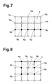
- Fig.7 is a diagram for explaining nodes of the temporary boundary face of an open type sipe.
- Fig.8 is a diagram for explaining nodes of the temporary boundary face of a closed type sipe.
- Fig.9 is a diagram for explaining a hexahedral solid element.
- Fig.10 is a diagram for explaining the direction to copy or shift a node.
- Fig.11 is a diagram perspectively showing a temporary boundary face and copied nodes.
- Fig.12 is a diagram perspectively showing the temporary boundary face and shifted nodes.
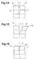
- Fig.13 is a diagram perspectively showing wall surfaces of the sipe.
- Fig.14 shows a cross section of the wall surfaces of the sipe.
- Figs.15 and 16 are the cross sections showing opening and closing of the wall surfaces.
- Fig.17 shows a practical example of the tread pattern of a tire.
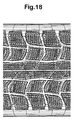
- Fig.18 shows a tread part of a finite element model of the tire.
- Fig.19 shows a finite element tire model in a state that a tire body model is partly combined with a tread model.
- Fig.20 is a diagram for explaining problems in the conventional method.
- the tire used is a pneumatic tire.
- the present invention may be applicable to not only a non-pneumatic tire but also a load supporting inner structure of a safety tire and the like.
- the tire is provided in the tread portion with sipes 2 and relatively wide tread grooves to form a tread pattern such as block pattern, rib pattern, block-rib pattern, rug pattern, rib-rug pattern and the like.
- the sipe 2 is a fine groove having a certain width w of not more than 2.0 mm, in this example less than 1.0 mm.
- Each sipe 2 can be formed as being (1) an open type (both ends are opened), (2) a closed type (both ends are closed) or (3) a semi-open type (one end is opened and the other end is closed).
- the closed end and the bottom are called "dead end”.
- the configuration of each sipe and the formation of the sipes are not specifically limited in the present invention.
- tread rubber T i.e. siped tread components
- Other parts of the tire such as tread reinforcing belt, carcass, bead core, bead apex rubber, bead rubber, sidewall rubber, and the like are suitably modeled according to the materials, positions and the like of the parts and simulation purpose.
- Fig.1 shows an exemplary tread block (B) as a part of the tread rubber T on the tread reinforcing belt, wherein a plurality of sipes 2 are disposed.
- a temporary boundary face 3 is defined for each of the sipe 2.
- the temporary boundary face 3 means the center plane of the sipe 2, that is, a face extending along the center of the width w of the sipe 2. In other words, this process is to find the center plane of the sipe in the widthwise direction and define the coordinates thereof in the three-dimensional coordinate system used to determine the divided finite elements. It is however not always necessary that the temporary boundary face 3 is the center plane. It may be defined off the center by adjusting the distances in the under-mentioned copying and shifting of the nodes.
- Fig.2 shows a part of a three-dimensional tread pattern corresponding to the part shown in Fig.1 which is visualized in an isometric drawing.
- the three-dimensional tread pattern means a set of data on coordinates P1, P2 --- Pn of various pints of the tread portion in the three-dimensional coordinate system (in this example X-Y-Z coordinate system) which data can specify the geometry of the tread portion.
- the temporary boundary faces 3 of the sipes 2 are visualized together with the tread block (B). When the sipe is flat as shown in Fig.1, the temporary boundary face 3 is a single flat face as shown in Fig.3.
- the temporary boundary face 3 is made up of a plurality of flat faces 3a-3f. If the sipe has a wavy configuration, the temporary boundary face 3 is made up of flat faces arranged zigzag to resemble the curved configuration.
- the tread rubber T is divided into a finite number of polyhedral solid elements E such as tetrahedral solid element, pentahedral solid element, hexahedral solid element and the like.
- each temporary boundary face 3 is made up of a plurality of element surfaces.
- the element surfaces are of the elements defined as being adjacent to the temporary boundary face 3. There is no element extending across the temporary boundary face 3, and some of the nodes of these element surfaces are positioned on the periphery of the temporary boundary face 3 and the rest are positioned on the inside thereof.
- a rigidity, material constants such as complex elastic modulus and loss tangent, hardness and the like of the tread rubber part which is represented by the element are defined.
- Fig.5 shows an example of the dividing of the same part as of Fig.1, wherein the tread block (B) is divided into hexahedral solid elements.
- a hexahedral solid element E has, as shown in Fig.9, six element surfaces and eight nodes N.
- Fig.6 shows a plane obtained by cutting along one of the temporary boundary faces 3 in Fig.5.
- the temporary boundary face 3 is distinguished by dotting.
- a part on each side of a sipe 2 is divided into six hexahedral solid elements. Therefore, the temporary boundary face 3 is made up of six quadrilateral element surface 3A-3F and their twelve nodes N1 to N12 are associated with the temporary boundary face 3.
- quadrilaterals and/or triangles are preferably used. But, other polygons may be used too.
- the nodes N (N1 to N12) associate with a temporary boundary face 3 include nodes Nb positioned at the "dead end" of the sipe (hereinafter, the "on-border node” Nb).
- the rest (hereinafter, the "off-border node Na") are positioned at other positions than the "dead end”.
- the on-border nodes Nb which are positioned at the bottom and one closed end are N4, N8, N9, N10, N11 and N12.
- the off-border nodes Na are N1,N2,N3,N5,N6 and N7.
- the on-border nodes Nb are positioned at the bottom only.
- the on-border nodes Nb are positioned at the bottom and both of the closed ends.
- the on-border nodes are indicated as a black dot. In other words, the coordinates of the nodes (N1 to N12) are so determined in dividing the tread rubber.
- Fig.11 is a visualization of the temporary boundary face 3 of Fig.6 in a perspective manner.
- each off-border node Na is copied to make a copied node Nc at a position at a small distance L from the original position whereas the on-border nodes Nb are not copied and their positions are not shifted.
- the above-mentioned small distance L is one half of the width W of the sipe 2 because the temporary boundary face 3 is the center plane. with respect to each temporary boundary face 3, all the copied positions are on the same side of the temporary boundary face 3.
- the direction from the original position to the copied position (hereinafter the "copy direction") is a direction of vector sum of normal vectors of the element surfaces which have the off-border node in common.
- the copy direction is determined from the normal vectors of the element surfaces 3A and 3B. Accordingly, when the element surfaces are substantially in a flat plane, the copy direction is normal to the flat plane.
- the temporary boundary face 3 is also zigzag as shown in Fig.10, normal vectors Va and Vb of element surfaces 3A and 3B which have an off-border node Na in common have different directions.
- the copy direction can be given as only one direction.
- the above-mentioned off-border node Na is shifted by the small distance L (w/2 in this example) on the other side of the temporary boundary face 3 than the copied node Nc as shown in Fig.12. (hereinafter the "shifted node Nd")
- the direction from the original position to the shift position is determined in the same way as the above-mentioned copy direction, using vectors.
- the copied nodes Nc, shifted nodes Nd and the on-border nodes Nb staying in the original positions are defined for each sipe 2.
- a pair of wall surfaces 4 and 5 are defined for each of the sipes 2.
- the wall surface 4 is defined by the copied nodes Nc and the on-border nodes Nb.
- the wall surface 5 is defined by the shifted nodes Nd and the on-border nodes Nb.
- the wall surface 4 consists of six element surfaces 4A, 4B, 4C, 4D, 4E and 4F which are of the elements E" remade to have the copied nodes Nc and the on-border nodes Nb.
- the wall surface 5 consists of six element surface 5A, 5B, 5C, 5D, 5E and 5F which are of the elements E' remade to have the shifted node Nd and the on-border nodes Nb.
- the hexahedral solid elements on both sides of the temporary boundary face 3 which originally have the off-border nodes Na and on-border nodes Nb are remade such that the hexahedral solid element E" on the wall surface 4 side have the copied nodes Nc and the on-border nodes Nb, and the hexahedral solid element E' on the wall surface 5 side have the shifted node Nd and the on-border nodes Nb.
- the original elements are converted as explained above, and the finite element model of the tread block is made.
- Figs.17-19 show a practical example.
- Fig.17 shows a practical tread pattern for a studless tire.
- the tread blocks are each provided with several zigzag sipes including an open type and semi-open type.
- a finite element model of the tread rubber can be made as explained above.
- Fig.18 shows such a tread model.
- a finite element model of a tire main body (part excluding the tread rubber) is separately made. Then, the tread model and tire main body model are combined.
- Fig.19 shows a state that the tire main body model is partly combined with the tread model Q. when combined entirely, a finite element tire model is completed.
- the making of the tire model is of course executed on a computer system.
- the computer automatically executes the following processes to make the tread model: determining the coordinates of the off-border node Na and on-border nodes Nb; determining the shift/copy directions; converting the above-mentioned determined coordinates into the coordinates of the copied nodes Nc and the coordinates of shifted node Nd; and remaking the elements using the converted coordinates so that elements on one side of a sipe have nodes in common with elements on the other side of the sipe at the dead end.
Landscapes
- Engineering & Computer Science (AREA)
- Physics & Mathematics (AREA)
- Theoretical Computer Science (AREA)
- Mechanical Engineering (AREA)
- Geometry (AREA)
- Computer Hardware Design (AREA)
- General Engineering & Computer Science (AREA)
- General Physics & Mathematics (AREA)
- Evolutionary Computation (AREA)
- Automation & Control Theory (AREA)
- Aviation & Aerospace Engineering (AREA)
- Computational Mathematics (AREA)
- Mathematical Analysis (AREA)
- Mathematical Optimization (AREA)
- Pure & Applied Mathematics (AREA)
- Tires In General (AREA)
Abstract
Description
As the adjacent elements (d) are relatively large - the width is usually at least 5 mm or 6 mm, if a load is applied to the block during rolling simulation, the block is deformed and the small element is crushed differently from the actual tire case. The crushing may be avoided if the size of the adjacent elements are decreased. In this case, however, as the number of the elements is excessively increased, it is difficult to shorten the computation time for simulating, and there is a possibility that the processing becomes impossible.
The nodes N (N1 to N12) associate with a
In this example, the above-mentioned small distance L is one half of the width W of the
with respect to each
The direction from the original position to the shift position is determined in the same way as the above-mentioned copy direction, using vectors.
the hexahedral solid element E' on the
Thus, the original elements are converted as explained above, and
the finite element model of the tread block is made.
Claims (6)
- A method of making a finite element model of a tire,
said tire comprising a tread portion provided with a fine groove having a dead end including at least a bottom,
the method comprising dividing said tread portion into elements so that the elements include first elements on one side of the fine groove and second elements on the other side of the fine groove, the first elements and second elements having on-border nodes in common at said dead end but the first elements and second elements not having nodes in common at other positions than said dead end. - The method according to claim 1, which further comprises
determining a temporary boundary face between the first elements and second elements,
defining nodes on the temporary boundary face which nodes include off-border nodes and the above-mentioned on-border nodes,
duplicating the off-border nodes so that doubled nodes are defined which doubled nodes are first nodes and second nodes spaced from the first nodes in the widthwise direction of the fine groove,
defining the first elements by using the first nodes and the on-border nodes, and
defining the second elements by using the second nodes and the on-border nodes. - The method according to claim 2, wherein
the off-border nodes on the temporary boundary face are copied to one side of the temporary boundary face to define the first nodes, and
the off-border nodes are shifted to the other side of the temporary boundary face to define the second nodes. - The method according to claim 3, wherein
the temporary boundary face is the center plane of the fine groove. - The method according to claim 3, wherein
the temporary boundary face is off the center of the width of the fine groove. - A finite element model of a tire,
said tire comprising a tread portion provided with a fine groove having a dead end including at least a bottom,
the finite element model made up of elements including first elements on one side of the fine groove and second elements on the other side of the fine groove,
the first elements and second elements having nodes in common at said dead end but the first elements and second elements not having nodes in common at other positions than said dead end.
Applications Claiming Priority (2)
| Application Number | Priority Date | Filing Date | Title |
|---|---|---|---|
| JP2001096629A JP3498064B2 (en) | 2001-03-29 | 2001-03-29 | How to create a tire finite element model |
| JP2001096629 | 2001-03-29 |
Publications (3)
| Publication Number | Publication Date |
|---|---|
| EP1245411A2 true EP1245411A2 (en) | 2002-10-02 |
| EP1245411A3 EP1245411A3 (en) | 2003-09-17 |
| EP1245411B1 EP1245411B1 (en) | 2006-03-22 |
Family
ID=18950527
Family Applications (1)
| Application Number | Title | Priority Date | Filing Date |
|---|---|---|---|
| EP02007026A Expired - Lifetime EP1245411B1 (en) | 2001-03-29 | 2002-03-27 | Method of making finite element model of tire having at least one fine groove |
Country Status (4)
| Country | Link |
|---|---|
| US (1) | US7280951B2 (en) |
| EP (1) | EP1245411B1 (en) |
| JP (1) | JP3498064B2 (en) |
| DE (1) | DE60209954T2 (en) |
Cited By (1)
| Publication number | Priority date | Publication date | Assignee | Title |
|---|---|---|---|---|
| EP2960080A1 (en) * | 2014-06-25 | 2015-12-30 | Sumitomo Rubber Industries, Ltd. | Method and system for estimating wear of axially divided tread zones of tire |
Families Citing this family (13)
| Publication number | Priority date | Publication date | Assignee | Title |
|---|---|---|---|---|
| JP4622336B2 (en) * | 2004-06-24 | 2011-02-02 | 横浜ゴム株式会社 | How to create a tire model |
| JP4615983B2 (en) * | 2004-12-15 | 2011-01-19 | 株式会社ブリヂストン | Tire model creation method, tire model, and tire behavior simulation method |
| JP4943893B2 (en) * | 2007-02-23 | 2012-05-30 | 株式会社ブリヂストン | Tire model creation method, tire model creation device, and tire model creation program |
| JP5526599B2 (en) * | 2009-05-19 | 2014-06-18 | 横浜ゴム株式会社 | Tread model creation method and computer program therefor, tire model creation method and computer program therefor |
| RU2531435C2 (en) * | 2009-05-29 | 2014-10-20 | Пирелли Тайр С.П.А. | Winter tire |
| JP5545826B2 (en) * | 2010-03-25 | 2014-07-09 | 株式会社ブリヂストン | Tire performance prediction method and tire performance prediction apparatus |
| JP5519366B2 (en) * | 2010-03-26 | 2014-06-11 | 株式会社ブリヂストン | How to create a tire model |
| JP5513200B2 (en) * | 2010-03-26 | 2014-06-04 | 株式会社ブリヂストン | How to create a tire model |
| JP5519365B2 (en) * | 2010-03-26 | 2014-06-11 | 株式会社ブリヂストン | How to create a tire model |
| JP6104572B2 (en) * | 2012-11-19 | 2017-03-29 | 東洋ゴム工業株式会社 | 3D sipe wall surface derivation method, derivation device, and derivation program |
| JP6454122B2 (en) * | 2014-10-07 | 2019-01-16 | 住友ゴム工業株式会社 | Prediction method of block stiffness |
| JP6930548B2 (en) * | 2017-01-26 | 2021-09-01 | 日本電気株式会社 | Detection system and detection method |
| CN115130351B (en) * | 2022-07-06 | 2025-04-15 | 中策橡胶集团股份有限公司 | A method and program product for quickly and automatically generating a finite element simulation model of asymmetric tire pattern |
Family Cites Families (8)
| Publication number | Priority date | Publication date | Assignee | Title |
|---|---|---|---|---|
| US5710718A (en) * | 1993-01-27 | 1998-01-20 | Bridgestone Corporation | Method of designing a pneumatic tire to achieve a best mode under given conditions |
| EP0919941B1 (en) * | 1997-11-25 | 2005-09-21 | Sumitomo Rubber Industries Limited | Method of and apparatus for simulating rolling tyre |
| ATE381004T1 (en) * | 1998-04-07 | 2007-12-15 | Pirelli | METHOD FOR DETERMINING THE ROAD BEHAVIOR OF A VEHICLE TIRE |
| DE69924464T2 (en) * | 1998-09-07 | 2006-03-16 | Bridgestone Corp. | METHOD OF PRESENTING THE EFFICIENCY OF A TIRE |
| US6456289B1 (en) * | 1999-04-23 | 2002-09-24 | Georgia Tech Research Corporation | Animation system and method for a animating object fracture |
| EP1297975B1 (en) * | 2000-06-14 | 2010-04-07 | Sumitomo Rubber Industries, Ltd. | Vehicle/tire performances simulating method |
| JP4723057B2 (en) * | 2000-06-29 | 2011-07-13 | 横浜ゴム株式会社 | Product shape design method and pneumatic tire designed using the same |
| JP3892652B2 (en) * | 2000-09-06 | 2007-03-14 | 住友ゴム工業株式会社 | Creating a tire analysis model |
-
2001
- 2001-03-29 JP JP2001096629A patent/JP3498064B2/en not_active Expired - Fee Related
-
2002
- 2002-03-27 EP EP02007026A patent/EP1245411B1/en not_active Expired - Lifetime
- 2002-03-27 DE DE60209954T patent/DE60209954T2/en not_active Expired - Lifetime
- 2002-03-29 US US10/108,720 patent/US7280951B2/en not_active Expired - Fee Related
Cited By (4)
| Publication number | Priority date | Publication date | Assignee | Title |
|---|---|---|---|---|
| EP2960080A1 (en) * | 2014-06-25 | 2015-12-30 | Sumitomo Rubber Industries, Ltd. | Method and system for estimating wear of axially divided tread zones of tire |
| CN105224711A (en) * | 2014-06-25 | 2016-01-06 | 住友橡胶工业株式会社 | For assessment of the method and system of the wearing and tearing of the axis segmentation tread area of tire |
| US10005328B2 (en) | 2014-06-25 | 2018-06-26 | Sumitomo Rubber Industries, Ltd. | Method and system for estimating wear of axially divided tread zones of tire |
| CN105224711B (en) * | 2014-06-25 | 2020-09-08 | 住友橡胶工业株式会社 | Method and system for evaluating wear of axially divided tread regions of a tire |
Also Published As
| Publication number | Publication date |
|---|---|
| US7280951B2 (en) | 2007-10-09 |
| JP3498064B2 (en) | 2004-02-16 |
| JP2002293114A (en) | 2002-10-09 |
| DE60209954T2 (en) | 2006-10-26 |
| EP1245411B1 (en) | 2006-03-22 |
| EP1245411A3 (en) | 2003-09-17 |
| US20020139469A1 (en) | 2002-10-03 |
| DE60209954D1 (en) | 2006-05-11 |
Similar Documents
| Publication | Publication Date | Title |
|---|---|---|
| US7908128B2 (en) | Method for modeling a tire model and simulation method | |
| EP1245411B1 (en) | Method of making finite element model of tire having at least one fine groove | |
| US6531012B2 (en) | Pneumatic tire designing method | |
| EP0919941B1 (en) | Method of and apparatus for simulating rolling tyre | |
| EP1030170A1 (en) | Tire performance predicting method | |
| JPWO1994016877A1 (en) | How to design pneumatic tires | |
| EP0924111B1 (en) | Pneumatic tire designing method | |
| JP4264102B2 (en) | How to create a tire model | |
| JPWO1998029270A1 (en) | How to design pneumatic tires | |
| JP2008262367A (en) | How to create a tire model | |
| JP2006011688A (en) | Method for preparing tire model | |
| JP2006018422A (en) | Tire finite element modelling method | |
| JP7215296B2 (en) | Tire simulation method | |
| JP4635562B2 (en) | Operation method of simulation apparatus | |
| JP5519366B2 (en) | How to create a tire model | |
| JP2006072896A (en) | Tire model generation method | |
| JP2010271767A (en) | Method of creating tread model and computer program therefor, and method of creating tire model and computer program therefor | |
| JP2017226392A (en) | Tire temperature simulation method | |
| JP7746836B2 (en) | Tire simulation method and simulation device | |
| JP2022064105A (en) | Method for creating numerical analysis model of tire | |
| JP7259515B2 (en) | How to create structure data | |
| JP4581649B2 (en) | Operation method of simulation apparatus | |
| KR100553229B1 (en) | Pneumatic tire designing method | |
| JP2025065938A (en) | How to create a tire model | |
| JP2007223504A (en) | Tire performance prediction method, apparatus, and storage medium |
Legal Events
| Date | Code | Title | Description |
|---|---|---|---|
| PUAI | Public reference made under article 153(3) epc to a published international application that has entered the european phase |
Free format text: ORIGINAL CODE: 0009012 |
|
| AK | Designated contracting states |
Kind code of ref document: A2 Designated state(s): AT BE CH CY DE DK ES FI FR GB GR IE IT LI LU MC NL PT SE TR |
|
| AX | Request for extension of the european patent |
Free format text: AL;LT;LV;MK;RO;SI |
|
| PUAL | Search report despatched |
Free format text: ORIGINAL CODE: 0009013 |
|
| AK | Designated contracting states |
Kind code of ref document: A3 Designated state(s): AT BE CH CY DE DK ES FI FR GB GR IE IT LI LU MC NL PT SE TR |
|
| AX | Request for extension of the european patent |
Extension state: AL LT LV MK RO SI |
|
| 17P | Request for examination filed |
Effective date: 20040303 |
|
| AKX | Designation fees paid |
Designated state(s): DE FR GB IT |
|
| 17Q | First examination report despatched |
Effective date: 20040820 |
|
| GRAP | Despatch of communication of intention to grant a patent |
Free format text: ORIGINAL CODE: EPIDOSNIGR1 |
|
| GRAS | Grant fee paid |
Free format text: ORIGINAL CODE: EPIDOSNIGR3 |
|
| GRAA | (expected) grant |
Free format text: ORIGINAL CODE: 0009210 |
|
| AK | Designated contracting states |
Kind code of ref document: B1 Designated state(s): DE FR GB IT |
|
| REG | Reference to a national code |
Ref country code: GB Ref legal event code: FG4D |
|
| REF | Corresponds to: |
Ref document number: 60209954 Country of ref document: DE Date of ref document: 20060511 Kind code of ref document: P |
|
| ET | Fr: translation filed | ||
| PLBE | No opposition filed within time limit |
Free format text: ORIGINAL CODE: 0009261 |
|
| STAA | Information on the status of an ep patent application or granted ep patent |
Free format text: STATUS: NO OPPOSITION FILED WITHIN TIME LIMIT |
|
| 26N | No opposition filed |
Effective date: 20061227 |
|
| PGFP | Annual fee paid to national office [announced via postgrant information from national office to epo] |
Ref country code: IT Payment date: 20080321 Year of fee payment: 7 |
|
| PGFP | Annual fee paid to national office [announced via postgrant information from national office to epo] |
Ref country code: GB Payment date: 20080402 Year of fee payment: 7 |
|
| GBPC | Gb: european patent ceased through non-payment of renewal fee |
Effective date: 20090327 |
|
| PG25 | Lapsed in a contracting state [announced via postgrant information from national office to epo] |
Ref country code: GB Free format text: LAPSE BECAUSE OF NON-PAYMENT OF DUE FEES Effective date: 20090327 |
|
| PG25 | Lapsed in a contracting state [announced via postgrant information from national office to epo] |
Ref country code: IT Free format text: LAPSE BECAUSE OF NON-PAYMENT OF DUE FEES Effective date: 20090327 |
|
| PGFP | Annual fee paid to national office [announced via postgrant information from national office to epo] |
Ref country code: FR Payment date: 20140311 Year of fee payment: 13 |
|
| PGFP | Annual fee paid to national office [announced via postgrant information from national office to epo] |
Ref country code: DE Payment date: 20140417 Year of fee payment: 13 |
|
| REG | Reference to a national code |
Ref country code: DE Ref legal event code: R119 Ref document number: 60209954 Country of ref document: DE |
|
| REG | Reference to a national code |
Ref country code: FR Ref legal event code: ST Effective date: 20151130 |
|
| PG25 | Lapsed in a contracting state [announced via postgrant information from national office to epo] |
Ref country code: DE Free format text: LAPSE BECAUSE OF NON-PAYMENT OF DUE FEES Effective date: 20151001 |
|
| PG25 | Lapsed in a contracting state [announced via postgrant information from national office to epo] |
Ref country code: FR Free format text: LAPSE BECAUSE OF NON-PAYMENT OF DUE FEES Effective date: 20150331 |