EP1245366B1 - Locking means for controlling the flow of a flowable medium - Google Patents
Locking means for controlling the flow of a flowable medium Download PDFInfo
- Publication number
- EP1245366B1 EP1245366B1 EP02012772A EP02012772A EP1245366B1 EP 1245366 B1 EP1245366 B1 EP 1245366B1 EP 02012772 A EP02012772 A EP 02012772A EP 02012772 A EP02012772 A EP 02012772A EP 1245366 B1 EP1245366 B1 EP 1245366B1
- Authority
- EP
- European Patent Office
- Prior art keywords
- locking means
- bolt
- channel
- flow
- inlet channel
- Prior art date
- Legal status (The legal status is an assumption and is not a legal conclusion. Google has not performed a legal analysis and makes no representation as to the accuracy of the status listed.)
- Expired - Lifetime
Links
Images

Classifications
-
- B—PERFORMING OPERATIONS; TRANSPORTING
- B29—WORKING OF PLASTICS; WORKING OF SUBSTANCES IN A PLASTIC STATE IN GENERAL
- B29C—SHAPING OR JOINING OF PLASTICS; SHAPING OF MATERIAL IN A PLASTIC STATE, NOT OTHERWISE PROVIDED FOR; AFTER-TREATMENT OF THE SHAPED PRODUCTS, e.g. REPAIRING
- B29C48/00—Extrusion moulding, i.e. expressing the moulding material through a die or nozzle which imparts the desired form; Apparatus therefor
- B29C48/25—Component parts, details or accessories; Auxiliary operations
- B29C48/27—Cleaning; Purging; Avoiding contamination
- B29C48/2725—Cleaning; Purging; Avoiding contamination of filters
- B29C48/273—Cleaning; Purging; Avoiding contamination of filters using back flow
-
- B—PERFORMING OPERATIONS; TRANSPORTING
- B29—WORKING OF PLASTICS; WORKING OF SUBSTANCES IN A PLASTIC STATE IN GENERAL
- B29C—SHAPING OR JOINING OF PLASTICS; SHAPING OF MATERIAL IN A PLASTIC STATE, NOT OTHERWISE PROVIDED FOR; AFTER-TREATMENT OF THE SHAPED PRODUCTS, e.g. REPAIRING
- B29C48/00—Extrusion moulding, i.e. expressing the moulding material through a die or nozzle which imparts the desired form; Apparatus therefor
- B29C48/25—Component parts, details or accessories; Auxiliary operations
- B29C48/36—Means for plasticising or homogenising the moulding material or forcing it through the nozzle or die
- B29C48/50—Details of extruders
- B29C48/69—Filters or screens for the moulding material
- B29C48/691—Arrangements for replacing filters, e.g. with two parallel filters for alternate use
- B29C48/6912—Arrangements for replacing filters, e.g. with two parallel filters for alternate use the filters being fitted on a single rectilinearly reciprocating slide
-
- B—PERFORMING OPERATIONS; TRANSPORTING
- B29—WORKING OF PLASTICS; WORKING OF SUBSTANCES IN A PLASTIC STATE IN GENERAL
- B29C—SHAPING OR JOINING OF PLASTICS; SHAPING OF MATERIAL IN A PLASTIC STATE, NOT OTHERWISE PROVIDED FOR; AFTER-TREATMENT OF THE SHAPED PRODUCTS, e.g. REPAIRING
- B29C48/00—Extrusion moulding, i.e. expressing the moulding material through a die or nozzle which imparts the desired form; Apparatus therefor
- B29C48/03—Extrusion moulding, i.e. expressing the moulding material through a die or nozzle which imparts the desired form; Apparatus therefor characterised by the shape of the extruded material at extrusion
-
- B—PERFORMING OPERATIONS; TRANSPORTING
- B29—WORKING OF PLASTICS; WORKING OF SUBSTANCES IN A PLASTIC STATE IN GENERAL
- B29C—SHAPING OR JOINING OF PLASTICS; SHAPING OF MATERIAL IN A PLASTIC STATE, NOT OTHERWISE PROVIDED FOR; AFTER-TREATMENT OF THE SHAPED PRODUCTS, e.g. REPAIRING
- B29C48/00—Extrusion moulding, i.e. expressing the moulding material through a die or nozzle which imparts the desired form; Apparatus therefor
- B29C48/25—Component parts, details or accessories; Auxiliary operations
- B29C48/254—Sealing means
- B29C48/2545—Sealing means for filters
Definitions
- the invention relates to a locking means for controlling the Flow of a flowable medium according to the generic term of the main claim.
- a generic device is described in DE 42 18 756 C1 described and creates the possibility with the previously large Extent of filter devices used in extrusion presses and injection molding machines to perform backwashing without that the purchase of new filter devices is necessary.
- an additional device is created that can be connected to existing facilities in order to in existing facilities, the downtimes, for example the sieves to raise.
- a filter device is described in the unpublished EP 08 75 357 A1 described for extrusion presses and injection molding machines, in which a bolt is used as a locking means, the is movable transversely to the direction of flow of the plastic stream, this bolt housed in a heatable additional housing is.
- the present invention has for its object a propose additional equipment that is as simple as possible, which can be connected to existing facilities and which, for. B. enables easy backwashing and at the same time as a so-called Starting valve can be used.
- the Locking device designed as a bolt and in an attachment housing is arranged.
- the bolt has a flow opening for the flowable medium, the flow opening thereby is formed that the bolt is preferably circumferential Has constriction through which the fluid flows or can be flowed around. This constriction ends at the mouth of the two inlet subchannels.
- the bolt is Slidable across the flowable medium and additionally points a main laxative duct and a partial laxative duct on connect the main discharge duct. By moving the bolt can now be reached a position in which the Main inlet channel via the constriction provided in the bolt is connected to an inlet subchannel.
- the trained according to the dependent claims Bolt that when the bolt assumes a position in which the main entry channel over the one provided in the bolt Constriction is connected to a partial inlet duct, the other inlet subchannel via a discharge subchannel with the Main discharge duct is connected, so that the loading of the tool connected to the filter device takes place, but at the same time the stopped sieve from the pure sieve side can flow through to the dirt screen side and the dirt particles detached here over the sieve assigned back inlet duct and then over a discharge duct into the main discharge duct.
- the main discharge duct opens into the atmosphere.
- the bolt designed as a locking means has on its A bypass channel on the side facing the main inlet channel, a connection depending on the position of the bolt between the main entrance duct and the outside atmosphere is able to manufacture.
- the blocking agent can be used to control flowable medium regardless of the medium to be controlled can take advantage of the below and in blocking agents used under protection become.
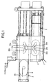
- two filter carrier bolts 2 are in a housing 1 and 3 arranged in the illustrated embodiment are arranged one above the other.
- filter elements 4 and 5 in sieve openings 28 and 29 provided that - as can be clearly seen from the drawing - are oval, with the long axis of the oval in Direction of displacement of portafilter bolts 2 and 3 extends and the length of the oval axis of the filter elements 4, 5 compared to the length of the housing bore in the housing 1 is selected such that only those used to seal the portafilter bolts 2, 3 required length in the housing bore Portafilter bolts 2, 3 is free of filter elements.
- Well-known ventilation grooves 20 are worked out in the portafilter bolts 2, 3.
- the sieve support bolt 2, 3 is displaced in itself known way via hydraulic or electrical devices and is controlled by appropriate controls - as general usual in the prior art - controlled.
- a locking means 10 is provided, which in the illustrated embodiment in connection with the housing 1 as follows is trained:
- the housing 1 has an inlet main channel 6 and one Main outlet channel 7, with front of main inlet channel 6 a screw not shown in the drawing is provided can be through which the plasticized plastic material fed to the main inlet channel 6 under a correspondingly high pressure becomes.
- the main inlet duct divides within the housing 1 6 in two inlet subchannels 8a and 8b, which with Screen openings 28 and 29 are connected, in which the Filter elements 4, 5 are arranged.
- On the pure screen side of the Sieve openings 28, 29 connect outlet partial channels 9a and 9b, which lead to an outlet main channel 7.
- a Additional housing 24 is provided, which is designed as a locking means Bolt 11 receives the hydraulic, pneumatic or other means transverse to the flow direction of the Plastic flow is displaceable. Open into this housing 24 Extensions of the inlet subchannels 8a and 8b on the one side and opposite on the other side of the Bolzens 11 opens the main inlet channel 6.
- the locking means can also be arranged in the housing 1 his.
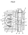
- the flow connection between the main inlet channel 6 and the inlet subchannels 8a and 8b is constricted reached in the bolt 11, wherein in the illustrated embodiment the bolt 11 is cylindrical, d. H. in the Cross section round and the constriction 12 over the whole
- the outer circumference of the bolt 11 is provided. That through that Housing 24 and the bolt 11 and the main inlet channel 6 device formed is referred to below as locking means 10, the bolt 11 can also be polygonal.
- the bolt 11 also has a main discharge duct 16, which is centered in the illustrated embodiment Viewed along the longitudinal axis of the bolt 11 and one end flows freely to the atmosphere.
- Two discharge duct 14 and 15 extend transversely to the longitudinal axis of the main discharge duct 16 and end at the end in the main discharge duct 16 and the other end on the outside of the pin 11.
- main or the discharge channels can also other configurations of the main or the discharge channels be provided.
- the bolt 11 is equipped with a bypass channel 27, which is arranged so that it is in fluid communication with the Main entry channel 6 can be brought, so that from the main entry channel 6 material not coming to the inlet subchannels 8a or 8b is led, but led away to the atmosphere can be.
- a bypass channel 27 which is arranged so that it is in fluid communication with the Main entry channel 6 can be brought, so that from the main entry channel 6 material not coming to the inlet subchannels 8a or 8b is led, but led away to the atmosphere can be.
- the bolt is in a such a position that the constriction 12 the flow of through the inlet main channel 6 supplied plastic material leads to partial inlet duct 8b.
- the material arrives from here to the filter element 5.
- Fig. 3 shows that by a slight displacement of the bolt 11 the constriction 12 also with the partial inlet duct 8a can come into contact, so that a flooding of the sieve opening 28 can be performed.
- Fig. 1 also shows that each entry sub-channel to the him assigned sieve opening in two inflow channels 22a, 23a or 22b and 23b opens, so that very favorable flow conditions for the large oval filter elements 4 and 5 can be achieved. 1 is also intended to illustrate that for each screen opening 28, 29 only one outflow channel 21 a or 21 b is provided.
Description
Die Erfindung bezieht sich auf ein Sperrmittel zur Steuerung des Durchflusses eines fließfähigen Mediums gemäß dem Oberbegriff des Hauptanspruches.The invention relates to a locking means for controlling the Flow of a flowable medium according to the generic term of the main claim.
Eine gattungsbildende Einrichtung wird in der DE 42 18 756 C1 beschrieben und schafft dieMöglichkeit, mit den bisher in großem Umfang eingesetzten Filtereinrichtungen bei Strangpressen und Spritzgießmaschinen ein Rückspülen durchzuführen, ohne dass die Anschaffung neuer Filtereinrichtungen notwendig ist. Bei dieser bekannten Einrichtung wird ein Zusatzgerät geschaffen, das an bestehende Einrichtungen anschließbar ist, um somit bei bestehenden Einrichtungen die Standzeiten, beispielsweise der Siebe, zu erhöhen.A generic device is described in DE 42 18 756 C1 described and creates the possibility with the previously large Extent of filter devices used in extrusion presses and injection molding machines to perform backwashing without that the purchase of new filter devices is necessary. In this known device, an additional device is created that can be connected to existing facilities in order to in existing facilities, the downtimes, for example the sieves to raise.
In der nicht vorveröffentlichten EP 08 75 357 A1 wird eine Filtereinrichtung für Strangpressen und Spritzgießmaschinen beschrieben, bei der ein Bolzen als Sperrmittel eingesetzt wird, der quer zur Strömungsrichtung des Kunststoffstromes bewegbar ist, wobei dieser Bolzen in einem beheizbaren Zusatzgehäuse untergebracht ist.A filter device is described in the unpublished EP 08 75 357 A1 described for extrusion presses and injection molding machines, in which a bolt is used as a locking means, the is movable transversely to the direction of flow of the plastic stream, this bolt housed in a heatable additional housing is.
Der vorliegenden Erfindung liegt die Aufgabe zugrunde, eine möglichst einfach aufgebaute Zusatzeinrichtung vorzuschlagen, die an bestehende Einrichtungen anschließbar ist und die z. B. ein problemloses Rückspülen ermöglicht und gleichzeitig als sogenanntes Anfahrventil genutzt werden kann.The present invention has for its object a propose additional equipment that is as simple as possible, which can be connected to existing facilities and which, for. B. enables easy backwashing and at the same time as a so-called Starting valve can be used.
Diese der Erfindung zugrundeliegende Aufgabe wird durch die
Lehre des Anspruches 1 gelöst.This object of the invention is achieved by
Teaching of
Vorteilhafte Ausgestaltungen sind in den abhängigen Ansprüchen erläutert.Advantageous refinements are in the dependent claims explained.
Mit anderen Worten ausgedrückt wird vorgeschlagen, dass das Sperrmittel als Bolzen ausgebildet und in einem Vorsatzgehäuse angeordnet ist. Der Bolzen weist eine Durchflussöffnung für das fließfähige Medium auf, wobei die Durchflussöffnung dadurch gebildet wird, dass der Bolzen eine vorzugsweise umlaufende Einschnürung aufweist, die von dem Fließmedium durchströmt bzw. umströmt werden kann. Diese Einschnürung mündet an der Mündung der beiden Eintrittsteilkanäle. Der Bolzen ist quer zum fließfähigen Medium verschiebbar und weist zusätzlich einen Abführhauptkanal und einen Abführteilkanal auf, die an den Abführhauptkanal anschließen. Durch Verschieben des Bolzens kann nunmehr eine Stellung erreicht werden, in der der Eintrittshauptkanal über die im Bolzen vorgesehene Einschnürung mit einem Eintrittsteilkanal verbunden ist. Über die heute üblichen Steuerungen kann dieser das Sperrmittel bildende Bolzen in eine solche Stellung verfahren werden, dass einerseits der zu der einen Sieböffnung führende Eintrittsteilkanal ganz .. abgeschlossen ist und andererseits die Möglichkeit besteht, trotz Beschicken des anderen Eintrittsteilkanales eine Verbindung zum anderen Eintrittsteilkanal zu schaffen, so dass hier ein Vorfluten der Sieböffnung ermöglicht wird. Der als Sperrmittel ausgebildete Bolzen weist an seiner dem Eintrittshauptkanal zugewandten Seite einen Bypasskanal auf, der in Abhängigkeit der Stellung des Bolzens eine Verbindung zwischen dem Eintrittshauptkanal und der Außenatmosphäre herzustellen in der Lage ist.In other words, it is suggested that the Locking device designed as a bolt and in an attachment housing is arranged. The bolt has a flow opening for the flowable medium, the flow opening thereby is formed that the bolt is preferably circumferential Has constriction through which the fluid flows or can be flowed around. This constriction ends at the mouth of the two inlet subchannels. The bolt is Slidable across the flowable medium and additionally points a main laxative duct and a partial laxative duct on connect the main discharge duct. By moving the bolt can now be reached a position in which the Main inlet channel via the constriction provided in the bolt is connected to an inlet subchannel. About today Conventional controls can form the blocking means Bolts are moved into such a position that on the one hand the partial inlet duct leading to the one sieve opening entirely .. completed and on the other hand there is the possibility, despite Feed a connection to the other inlet subchannel to create the other inlet subchannel, so that here a flooding the sieve opening is made possible. The trained as a blocking agent Bolt points on its side facing the main inlet duct Side of a bypass channel that depends on the Position of the bolt connects between the main inlet duct and able to produce the outside atmosphere is.
Außerdem ermöglicht der gemäß den Unteransprüchen ausgebildete Bolzen, dass dann, wenn der Bolzen eine Stellung einnimmt, in der der Eintrittshauptkanal über die im Bolzen vorgesehene Einschnürung mit einem Eintrittsteilkanal verbunden ist, der andere Eintrittsteilkanal über einen Abführteilkanal mit dem Abführhauptkanal verbunden ist, so dass also das Beschicken des an die Filtereinrichtung anschließenden Werkzeuges weiterhin erfolgt, gleichzeitig aber das stillgesetzte Sieb von der Reinsiebseite zur Schmutzsiebseite hin durchströmt werden kann und die hier abgelösten Schmutzpartikel über den diesem Sieb zugeordneten Eintrittsteilkanal zurückgespült und sodann über einen Abführteilkanal in den Abführhauptkanal geführt werden. Der Abführhauptkanal mündet hiermit in die Atmosphäre. In addition, the trained according to the dependent claims Bolt that when the bolt assumes a position in which the main entry channel over the one provided in the bolt Constriction is connected to a partial inlet duct, the other inlet subchannel via a discharge subchannel with the Main discharge duct is connected, so that the loading of the tool connected to the filter device takes place, but at the same time the stopped sieve from the pure sieve side can flow through to the dirt screen side and the dirt particles detached here over the sieve assigned back inlet duct and then over a discharge duct into the main discharge duct. The main discharge duct opens into the atmosphere.
Der als Sperrmittel ausgebildete Bolzen weist an seiner dem Eintrittshauptkanal zugewandten Seite einen Bypasskanal auf, der in Abhängigkeit der Stellung des Bolzens eine Verbindung zwischen dem Eintrittshauptkanal und der Außenatmosphäre herzustellen in der Lage ist.The bolt designed as a locking means has on its A bypass channel on the side facing the main inlet channel, a connection depending on the position of the bolt between the main entrance duct and the outside atmosphere is able to manufacture.
Ein Ausführungsbeispiel der Erfindung wird nachfolgend am Beispiel einer Filtereinrichtung für Strangpressen und Spritzgießmaschinen anhand der Zeichnungen erläutert. Die Zeichnungen zeigen dabei in
- Fig. 1
- eine Filtereinrichtung mit zwei Siebträgerbolzen und je einem in jedem Siebträgerbolzen angeordneten großen ovalen Sieb, in
- Fig. 2
- die Sperrstellung des oberen Siebträgerbolzens und in
- Fig. 3
- die Vorflutstellung für die Sieböffnung im oberen
Siebbolzen, wobei in Fig. 2 und Fig. 3 die Ein-
Trittsteilkanäle 8a und 8b im Schnitt um etwa 30° versetzt gezeichnet sind.
- Fig. 1
- a filter device with two portafilter bolts and one large oval sieve arranged in each portafilter bolt, in
- Fig. 2
- the locked position of the upper portafilter bolt and in
- Fig. 3
- the outflow position for the sieve opening in the upper sieve bolt, the inlet and
partial channels
Das Sperrmittel kann zur Steuerung fließfähigen Mediums eingesetzt werden und unabhängig von dem zu steuernden Medium können die Vorteile des nachfolgend beschriebenen und in den Ansprüchen unter Schutz gestellten Sperrmittels eingesetzt werden.The blocking agent can be used to control flowable medium regardless of the medium to be controlled can take advantage of the below and in blocking agents used under protection become.
Gemäß Fig. 1 sind in einem Gehäuse 1 zwei Siebträgerbolzen 2
und 3 angeordnet, die bei dem dargestellten Ausführungsbeispiel
übereinander angeordnet sind. In den Siebträgerbolzen 2
und 3 sind in Sieböffnungen 28 und 29 Filterelemente 4 und 5
vorgesehen, die - wie aus der Zeichnung deutlich ersichtlich -
oval ausgebildet sind, wobei sich die lange Achse des Ovals in
Richtung der Verschieberichtung der Siebträgerbolzen 2 und 3
erstreckt und die Länge der ovalen Achse der Filterelemente 4,
5 gegenüber der Länge der Gehäusebohrung im Gehäuse 1
derart gewählt ist, daß nur die zur Abdichtung der Siebträgerbolzen
2, 3 in der Gehäusebohrung erforderliche Länge der
Siebträgerbolzen 2, 3 filterelementfrei ist. An sich bekannte Lüftungsnuten
20 sind in den Siebträgerbolzen 2, 3 ausgearbeitet.1, two
Aus der Darstellung gemäß Fig. 1 ist ersichtlich, daß kurz nach
Beginn der Ausschiebebewegung des einen oder anderen
Siebträgerbolzens 2 oder 3 die periphere Randseite der jeweiligen
Filterelemente 4 oder 5 bereits mit der Außenatmosphäre in
Verbindung kommt, während der übrige Teil der Filterelemente 4
oder 5 noch mit der Zuführung des zu filtrierenden oder gefilterten
Kunststoffmaterials in Verbindung steht, so daß hier eine
unmittelbare Verbindung zwischen der Zufuhr des Kunststoffmaterials
oder der Abfuhr des Kunststoffmaterials mit der Außenatmosphäre
erfolgen würde.1 that shortly after
Start of the push-out movement of one or the
Die Verschiebung des Siebträgerbolzens 2, 3 erfolgt in an sich
bekannter Weise über hydraulische oder elektrische Einrichtungen
und wird über entsprechende Steuerungen - wie allgemein
im Stand der Technik üblich - gesteuert. The
Um diese schädliche Verbindung zwischen der Sieböffnung und
der Außenatmosphäre zu verhindern, wird gemäß der Erfindung
ein Sperrmittel 10 vorgesehen, das bei dem dargestellten Ausführungsbeispiel
in Verbindung mit dem Gehäuse 1 wie folgt
ausgebildet ist:To this harmful connection between the sieve opening and
To prevent the outside atmosphere is according to the invention
a
Das Gehäuse 1 weist einen Eintrittshauptkanal 6 und einen
Austrittshauptkanal 7 auf, wobei vor dem Eintrittshauptkanal 6
eine in der Zeichnung nicht dargestellte Schnecke vorgesehen
sein kann, durch welche das plastifizierte Kunststoffmaterial
dem Eintrittshauptkanal 6 unter entsprechend hohem Druck zugeführt
wird. Innerhalb des Gehäuses 1 teilt sich der Eintrittshauptkanal
6 in zwei Eintrittsteilkanäle 8a und 8b, die mit
Sieböffnungen 28 bzw. 29 in Verbindung stehen, in denen die
Filterelemente 4, 5 angeordnet sind. An die Reinsiebseite der
Sieböffnungen 28, 29 schließen Austrittsteilkanäle 9a und 9b an,
die zu einem Austrittshauptkanal 7 führen.The
Vor dem eigentlichen Gehäuse 1 der Filtereinrichtung ist ein
Zusatzgehäuse 24 vorgesehen, das einen als Sperrmittel ausgebildeten
Bolzen 11 aufnimmt, der über hydraulische, pneumatische
oder sonstige Mittel quer zur Strömungsrichtung des
Kunststoffstromes verschiebbar ist. In diesem Gehäuse 24 münden
Verlängerungen der Eintrittsteilkanäle 8a und 8b auf der
einen Seite und gegenüberliegend auf der anderen Seite des
Bolzens 11 mündet der Haupteintrittskanal 6. Anstelle eines Zusatzgehäuses
kann das Sperrmittel auch in dem Gehäuse 1 angeordnet
sein.In front of the
Die Fließverbindung zwischen dem Eintrittshauptkanal 6 und
den Eintrittsteilkanälen 8a und 8b wird durch eine Einschnürung
im Bolzen 11 erreicht, wobei bei dem dargestellten Ausführungsbeispiel
der Bolzen 11 zylindrisch ausgebildet ist, d. h. im
Querschnitt rund und die Einschnürung 12 über den ganzen
Außenumfang des Bolzens 11 vorgesehen wird. Das durch das
Gehäuse 24 und dem Bolzen 11 sowie den Eintrittshauptkanal 6
gebildete Gerät wird nachfolgend als Sperrmittel 10 bezeichnet,
wobei der Bolzen 11 auch polygonal ausgebildet sein kann.
Der Bolzen 11 weist weiterhin einen Abführhauptkanal 16 auf,
der sich bei dem dargestellten Ausführungsbeispiel zentrisch in
Längsachse des Bolzens 11 gesehen erstreckt und einenendes
zur Atmosphäre hin frei mündet. Zwei Abführteilkanäle 14 und
15 erstrecken sich quer zur Längsachse des Abführhauptkanales
16 und münden einenendes in den Abführhauptkanal 16 und
anderenendes an der Außenseite des Bolzens 11. Natürlich
können auch andere Ausgestaltungen des oder der Abführhauptkanäle
vorgesehen sein.The flow connection between the
Zusätzlich ist der Bolzen 11 mit einem Bypasskanal 27 ausgerüstet,
der so angeordnet ist, daß er in Fließverbindung mit dem
Eintrittshauptkanal 6 bringbar ist, so daß das aus dem Eintrittshauptkanal
6 kommende Material nicht zu den Eintrittsteilkanälen
8a oder 8b geführt wird, sondern zur Atmosphäre hin abgeführt
werden kann. Beim Start des Extruders wird verunreinigte
und vercrakte Schmelze ungefiltert durch den Bypasskanal 27
nach außen abgelassen und erst nach diesem Prozeß wird die
Produktion gestartetIn addition, the
Bei der Darstellung gemäß Fig. 2 befindet sich der Bolzen in einer
solchen Stellung, daß die Einschnürung 12 den Strom des
durch den Eintrittshauptkanal 6 zugeführten Kunststoffmateriales
zum Eintrittsteilkanal 8b führt. Von hier aus gelangt das Material
zum Filterelement 5.2, the bolt is in a
such a position that the
Fig. 3 zeigt, daß durch eine geringfügige Verschiebung des Bolzens
11 die Einschnürung 12 auch mit dem Eintrittsteilkanal 8a
in Verbindung kommen kann, so daß ein Vorfluten der Sieböffnung
28 durchgeführt werden kann. Fig. 3 shows that by a slight displacement of the
Fig. 1 zeigt weiterhin, daß jeder Eintrittsteilkanal sich zu der ihm
zugeordneten Sieböffnung in zwei Anströmkanälen 22a, 23a
bzw. 22b und 23b öffnet, so daß sehr günstige Anströmverhältnisse
für die großen ovalen Filterelemente 4 bzw. 5 erreicht werden.
Die Fig. 1 soll auch verdeutlichen, daß je Sieböffnung 28,
29 nur ein Abströmkanal 21 a bzw. 21 b vorgesehen ist.Fig. 1 also shows that each entry sub-channel to the him
assigned sieve opening in two
Durch den Einsatz des vorbeschriebenen Sperrmittels 10 wird erreicht, daß dieses Sperrmittel auch bei anders ausgebildeten Extruderanordnungen in einfachster Weise als Anfahrventil und zum Rückspülen eingesetzt werden kann, so daß mit einem solchen Sperrmittel die unterschiedlichsten Aufgaben bei Filtereinrichtungen erreichbar sind.By using the locking means 10 described above achieved that this locking means even in other trained Extruder arrangements in the simplest way as a starting valve and can be used for backwashing, so that with such Blocking means a wide variety of tasks in filter devices are reachable.
Claims (9)
- Locking means for controlling the flow of a flowable medium with filter elements (4, 5) arranged in at least two separate channels of a housing (1) between at least one main inlet channel (6) and at least one main outlet channel (7), the locking means (10) being arranged in the area of the main inlet channel (6) upstream the filter elements (4, 5) and, in the continuous flow position, not hindering the flowable medium flowing from the main inlet channel (6) to the filter elements (4, 5) but, in a locking position, separating the continuous flow of the medium in a partial inlet channel (8a or 8b) from the main inlet channel (6), characterised in that the locking means (10) is formed by a bolt (11) which traverses the main inlet channel (6), is adjustable in a transverse direction to the direction of flow of the flowable medium and arranged in a housing (24) and the flow path from the main inlet channel (6) to an outlet channel is formed by a constriction (12) in the outer circumference of the bolt, the bolt (11) having a by-pass channel (27) on its side facing the main inlet channel (6), which by-pass channel is capable of forming a connection between the main inlet channel (6) and the external atmosphere as a function of the position of the bolt (11).
- Locking means according to claim 1 characterised in that the outlet of the by-pass channel (27)) into the main inlet channel (6) is arranged such that the main inlet channel (6) can be brought into flow connection both with the constriction (12) and with the by-pass (27) but the connection between the main inlet channel (6) and the constriction (12) can be closed by adjusting the bolt (11) while the connection between the main inlet channel (6) and the by-pass channel (27) is opened.
- Locking means according to claim 1 or 2 characterised in that the bolt (11) of the locking means (10) in addition to its movement in the longitudinal axis is also rotatable around the longitudinal axis.
- Locking means according to claim 1 characterised in that the constriction (12) is formed in a flow-enhancing manner.
- Locking means according to any of the preceding claims characterised by a main discharge channel (16) in the bolt (11) which opens at one end towards the atmosphere and to which two partial discharge channels (14, 15) are connected which, on displacement of the bolt (11), can be brought into flow connection with one of the partial inlet channels (8a, 8b).
- Locking means according to any of claims 1 to 5 characterised in that , in the case of the flow connection of the partial discharge channel (14, 15) with the corresponding partial inlet channels (8a, 8b), the cross-section of flow in the transition zone between the partial inlet channels (8a, 8b) and the partial discharge channels (14, 15) is smaller than the cross-section of flow of the partial inlet channels (8a, 8b).
- Locking means according to one of the preceding claims 1 to 3 characterised in that the locking means (10) is arranged in its own housing (17) which can be connected to a housing (1) in one operational direction.
- Locking means according to any of the preceding claims characterised in that the locking means (10) is arranged in the housing (1) of a screen changer.
- Locking means according to claim 1 characterised in that the bolt (11) is formed with a round cross-section and the constriction (12) is provided over the entire circumference of the bolt (11).
Applications Claiming Priority (5)
| Application Number | Priority Date | Filing Date | Title |
|---|---|---|---|
| DE19819195 | 1998-04-30 | ||
| DE19819195 | 1998-04-30 | ||
| DE19834302 | 1998-07-30 | ||
| DE19834302A DE19834302C2 (en) | 1998-04-30 | 1998-07-30 | Filter device for extrusion presses and injection molding machines |
| EP99948547A EP1082205B1 (en) | 1998-04-30 | 1999-04-03 | Filter device for extruders and injection moulding machines |
Related Parent Applications (2)
| Application Number | Title | Priority Date | Filing Date |
|---|---|---|---|
| EP99948547A Division EP1082205B1 (en) | 1998-04-30 | 1999-04-03 | Filter device for extruders and injection moulding machines |
| EP99948547.7 Division | 1999-04-03 |
Publications (3)
| Publication Number | Publication Date |
|---|---|
| EP1245366A2 EP1245366A2 (en) | 2002-10-02 |
| EP1245366A3 EP1245366A3 (en) | 2002-10-09 |
| EP1245366B1 true EP1245366B1 (en) | 2004-03-03 |
Family
ID=7866200
Family Applications (1)
| Application Number | Title | Priority Date | Filing Date |
|---|---|---|---|
| EP02012772A Expired - Lifetime EP1245366B1 (en) | 1998-04-30 | 1999-04-03 | Locking means for controlling the flow of a flowable medium |
Country Status (2)
| Country | Link |
|---|---|
| EP (1) | EP1245366B1 (en) |
| DE (3) | DE19834302C2 (en) |
Cited By (1)
| Publication number | Priority date | Publication date | Assignee | Title |
|---|---|---|---|---|
| EP4093593B1 (en) * | 2020-01-21 | 2023-10-25 | Aurotec GmbH | Valve and method of transporting fluids |
Families Citing this family (3)
| Publication number | Priority date | Publication date | Assignee | Title |
|---|---|---|---|---|
| AT412530B (en) * | 2002-10-28 | 2005-04-25 | Erema | REFILLABLE FILTER DEVICE FOR MELTED MATERIAL AND DISTRIBUTOR FOR SUCH A FILTER DEVICE |
| DE102007059579A1 (en) | 2007-07-30 | 2009-02-05 | Kreyenborg Verwaltungen Und Beteiligungen Gmbh & Co. Kg | Device for filtering a fluid, in particular a liquefied plastic |
| DE102014009768B4 (en) | 2014-07-01 | 2018-05-24 | Maag Automatik Gmbh | Device for filtering a plastic melt |
Family Cites Families (3)
| Publication number | Priority date | Publication date | Assignee | Title |
|---|---|---|---|---|
| DE4218756C1 (en) * | 1992-05-22 | 1993-04-29 | Kreyenborg Verwaltungen Und Beteiligungen Kg, 4400 Muenster, De | Injection moulding machine and extrusion press filter appts. for thermoplastics - comprises barrier member in inlet channel prior to sieve bolt and housing for unimpeded plastic flow in open barrier position, for efficient continual working |
| DE29517140U1 (en) * | 1995-03-31 | 1996-01-18 | Kreyenborg Verwaltungen | Filter device for extrusion presses and injection molding machines |
| EP0875357B1 (en) * | 1997-05-02 | 2001-11-07 | Kreyenborg Verwaltungen und Beteiligungen GmbH & Co. KG | Filter device for extruders and injection machines |
-
1998
- 1998-07-30 DE DE19834302A patent/DE19834302C2/en not_active Expired - Fee Related
-
1999
- 1999-04-03 EP EP02012772A patent/EP1245366B1/en not_active Expired - Lifetime
- 1999-04-03 DE DE59908788T patent/DE59908788D1/en not_active Expired - Lifetime
- 1999-04-03 DE DE59904459T patent/DE59904459D1/en not_active Expired - Lifetime
Cited By (1)
| Publication number | Priority date | Publication date | Assignee | Title |
|---|---|---|---|---|
| EP4093593B1 (en) * | 2020-01-21 | 2023-10-25 | Aurotec GmbH | Valve and method of transporting fluids |
Also Published As
| Publication number | Publication date |
|---|---|
| DE59904459D1 (en) | 2003-04-10 |
| EP1245366A2 (en) | 2002-10-02 |
| DE19834302C2 (en) | 2001-02-22 |
| DE19834302A1 (en) | 1999-11-11 |
| DE59908788D1 (en) | 2004-04-08 |
| EP1245366A3 (en) | 2002-10-09 |
Similar Documents
| Publication | Publication Date | Title |
|---|---|---|
| EP0672443B1 (en) | Control and filtering device for at least two partial fluid streams | |
| EP2576180B1 (en) | Filtering apparatus for highly viscous media | |
| DE2256639B1 (en) | FILTER DEVICE FOR EXTRUSION PRESSES AND INJECTION MOLDING MACHINES | |
| EP0433587A2 (en) | Screen changer apparatus with cylindrical screens | |
| EP1082205B1 (en) | Filter device for extruders and injection moulding machines | |
| DE19519907C2 (en) | Screen changing device for plastics processing plants | |
| DE10056557A1 (en) | Backwashing device for filter for plastic melts in injection molding machine comprises housing with inlet connected to feed channels and backwash channels and rotary pistons containing eccentric bores of same diameter as feed channels | |
| EP0536359B1 (en) | Filter-change module | |
| EP1245366B1 (en) | Locking means for controlling the flow of a flowable medium | |
| EP0875357B1 (en) | Filter device for extruders and injection machines | |
| DE4218756C1 (en) | Injection moulding machine and extrusion press filter appts. for thermoplastics - comprises barrier member in inlet channel prior to sieve bolt and housing for unimpeded plastic flow in open barrier position, for efficient continual working | |
| EP0919353B1 (en) | Filter apparatus for a fluid stream and filter module for use in such an apparatus | |
| WO2007085220A1 (en) | Device for filtering a liquid synthetic material | |
| DE19730574C1 (en) | Filter unit for prolonged operation feeding extruders | |
| DE4130002C1 (en) | Distribution point for extrusion press and injection, moulding machine - includes housing, supply unit, vertical bolt unit and inlet connection channel | |
| EP1762364A2 (en) | Device for filtering a fluid, especially for plastic-processing installations | |
| DE19500060C1 (en) | Filter for thermoplastic extrusion and injection moulding machine | |
| EP1524022B1 (en) | Device for filtering a liquid, especially for plastics processing plants | |
| DE4420119C1 (en) | Continuous filter for thermoplastic polymer | |
| WO2002016113A2 (en) | Device for filtering liquid media, support body and a method for operating the device | |
| DE102004010968B4 (en) | Device for filtering a fluid, in particular a liquefied plastic | |
| DE19509059C1 (en) | Controlled sepn. into two-stream fluid system | |
| DE3714593C2 (en) | ||
| EP3354440A1 (en) | Method for discharging polymer melt via a startup-valve, and startup-valve | |
| DE19519519C2 (en) | Control device for at least one fluid flow |
Legal Events
| Date | Code | Title | Description |
|---|---|---|---|
| PUAI | Public reference made under article 153(3) epc to a published international application that has entered the european phase |
Free format text: ORIGINAL CODE: 0009012 |
|
| PUAL | Search report despatched |
Free format text: ORIGINAL CODE: 0009013 |
|
| AC | Divisional application: reference to earlier application |
Ref document number: 1082205 Country of ref document: EP |
|
| AK | Designated contracting states |
Kind code of ref document: A2 Designated state(s): AT DE IT |
|
| AK | Designated contracting states |
Kind code of ref document: A3 Designated state(s): AT DE IT |
|
| 17P | Request for examination filed |
Effective date: 20020912 |
|
| 17Q | First examination report despatched |
Effective date: 20021217 |
|
| RAP3 | Party data changed (applicant data changed or rights of an application transferred) |
Owner name: KREYENBORG VERWALTUNG UND BETEILIGUNGEN GMBH & |
|
| RAP3 | Party data changed (applicant data changed or rights of an application transferred) |
Owner name: KREYENBORG VERWALTUNGEN UND BETEILIGUNGEN GMBH &AM |
|
| AKX | Designation fees paid |
Designated state(s): AT DE IT |
|
| GRAP | Despatch of communication of intention to grant a patent |
Free format text: ORIGINAL CODE: EPIDOSNIGR1 |
|
| GRAS | Grant fee paid |
Free format text: ORIGINAL CODE: EPIDOSNIGR3 |
|
| GRAA | (expected) grant |
Free format text: ORIGINAL CODE: 0009210 |
|
| AC | Divisional application: reference to earlier application |
Ref document number: 1082205 Country of ref document: EP Kind code of ref document: P |
|
| AK | Designated contracting states |
Kind code of ref document: B1 Designated state(s): AT DE IT |
|
| REF | Corresponds to: |
Ref document number: 59908788 Country of ref document: DE Date of ref document: 20040408 Kind code of ref document: P |
|
| PLBE | No opposition filed within time limit |
Free format text: ORIGINAL CODE: 0009261 |
|
| STAA | Information on the status of an ep patent application or granted ep patent |
Free format text: STATUS: NO OPPOSITION FILED WITHIN TIME LIMIT |
|
| 26N | No opposition filed |
Effective date: 20041206 |
|
| REG | Reference to a national code |
Ref country code: DE Ref legal event code: R082 Ref document number: 59908788 Country of ref document: DE Representative=s name: HABBEL & HABBEL, DE |
|
| REG | Reference to a national code |
Ref country code: DE Ref legal event code: R081 Ref document number: 59908788 Country of ref document: DE Owner name: NORDSON HOLDINGS S.A.R.L. & CO. KG, DE Free format text: FORMER OWNER: KREYENBORG VERWALTUNGEN UND BETEILIGUNGEN GMBH & CO. KG, 48157 MUENSTER, DE Effective date: 20140917 Ref country code: DE Ref legal event code: R082 Ref document number: 59908788 Country of ref document: DE Representative=s name: HABBEL & HABBEL, DE Effective date: 20140917 Ref country code: DE Ref legal event code: R082 Ref document number: 59908788 Country of ref document: DE Representative=s name: EISENFUEHR SPEISER PATENTANWAELTE RECHTSANWAEL, DE Effective date: 20140917 |
|
| PGFP | Annual fee paid to national office [announced via postgrant information from national office to epo] |
Ref country code: DE Payment date: 20150421 Year of fee payment: 17 |
|
| REG | Reference to a national code |
Ref country code: AT Ref legal event code: PC Ref document number: 260747 Country of ref document: AT Kind code of ref document: T Owner name: NORDSON HOLDINGS S.A.R.L. & CO. KG, DE Effective date: 20150618 |
|
| PGFP | Annual fee paid to national office [announced via postgrant information from national office to epo] |
Ref country code: IT Payment date: 20150428 Year of fee payment: 17 Ref country code: AT Payment date: 20150421 Year of fee payment: 17 |
|
| REG | Reference to a national code |
Ref country code: DE Ref legal event code: R082 Ref document number: 59908788 Country of ref document: DE Representative=s name: EISENFUEHR SPEISER PATENTANWAELTE RECHTSANWAEL, DE |
|
| REG | Reference to a national code |
Ref country code: DE Ref legal event code: R119 Ref document number: 59908788 Country of ref document: DE |
|
| REG | Reference to a national code |
Ref country code: AT Ref legal event code: MM01 Ref document number: 260747 Country of ref document: AT Kind code of ref document: T Effective date: 20160403 |
|
| PG25 | Lapsed in a contracting state [announced via postgrant information from national office to epo] |
Ref country code: DE Free format text: LAPSE BECAUSE OF NON-PAYMENT OF DUE FEES Effective date: 20161101 |
|
| PG25 | Lapsed in a contracting state [announced via postgrant information from national office to epo] |
Ref country code: IT Free format text: LAPSE BECAUSE OF NON-PAYMENT OF DUE FEES Effective date: 20160403 Ref country code: AT Free format text: LAPSE BECAUSE OF NON-PAYMENT OF DUE FEES Effective date: 20160403 |