EP1524022B1 - Device for filtering a liquid, especially for plastics processing plants - Google Patents
Device for filtering a liquid, especially for plastics processing plants Download PDFInfo
- Publication number
- EP1524022B1 EP1524022B1 EP04030092A EP04030092A EP1524022B1 EP 1524022 B1 EP1524022 B1 EP 1524022B1 EP 04030092 A EP04030092 A EP 04030092A EP 04030092 A EP04030092 A EP 04030092A EP 1524022 B1 EP1524022 B1 EP 1524022B1
- Authority
- EP
- European Patent Office
- Prior art keywords
- duct
- filter
- outfeed
- infeed
- housing
- Prior art date
- Legal status (The legal status is an assumption and is not a legal conclusion. Google has not performed a legal analysis and makes no representation as to the accuracy of the status listed.)
- Expired - Lifetime
Links
- 229920003023 plastic Polymers 0.000 title claims description 6
- 239000004033 plastic Substances 0.000 title claims description 6
- 238000001914 filtration Methods 0.000 title claims description 4
- 238000012545 processing Methods 0.000 title description 2
- 239000007788 liquid Substances 0.000 title 1
- 239000012530 fluid Substances 0.000 claims description 8
- 238000000034 method Methods 0.000 description 6
- 238000006073 displacement reaction Methods 0.000 description 4
- 238000011001 backwashing Methods 0.000 description 3
- 230000002411 adverse Effects 0.000 description 2
- 238000004519 manufacturing process Methods 0.000 description 2
- 238000004891 communication Methods 0.000 description 1
- 239000000356 contaminant Substances 0.000 description 1
- 238000013461 design Methods 0.000 description 1
- 238000011161 development Methods 0.000 description 1
- 230000018109 developmental process Effects 0.000 description 1
- 238000005265 energy consumption Methods 0.000 description 1
- 235000015114 espresso Nutrition 0.000 description 1
- 239000012535 impurity Substances 0.000 description 1
- 238000001746 injection moulding Methods 0.000 description 1
- 238000012423 maintenance Methods 0.000 description 1
- 230000014759 maintenance of location Effects 0.000 description 1
- 230000000717 retained effect Effects 0.000 description 1
Images


Classifications
-
- B—PERFORMING OPERATIONS; TRANSPORTING
- B01—PHYSICAL OR CHEMICAL PROCESSES OR APPARATUS IN GENERAL
- B01D—SEPARATION
- B01D29/00—Filters with filtering elements stationary during filtration, e.g. pressure or suction filters, not covered by groups B01D24/00 - B01D27/00; Filtering elements therefor
- B01D29/01—Filters with filtering elements stationary during filtration, e.g. pressure or suction filters, not covered by groups B01D24/00 - B01D27/00; Filtering elements therefor with flat filtering elements
-
- B—PERFORMING OPERATIONS; TRANSPORTING
- B01—PHYSICAL OR CHEMICAL PROCESSES OR APPARATUS IN GENERAL
- B01D—SEPARATION
- B01D29/00—Filters with filtering elements stationary during filtration, e.g. pressure or suction filters, not covered by groups B01D24/00 - B01D27/00; Filtering elements therefor
- B01D29/50—Filters with filtering elements stationary during filtration, e.g. pressure or suction filters, not covered by groups B01D24/00 - B01D27/00; Filtering elements therefor with multiple filtering elements, characterised by their mutual disposition
- B01D29/52—Filters with filtering elements stationary during filtration, e.g. pressure or suction filters, not covered by groups B01D24/00 - B01D27/00; Filtering elements therefor with multiple filtering elements, characterised by their mutual disposition in parallel connection
-
- B—PERFORMING OPERATIONS; TRANSPORTING
- B01—PHYSICAL OR CHEMICAL PROCESSES OR APPARATUS IN GENERAL
- B01D—SEPARATION
- B01D29/00—Filters with filtering elements stationary during filtration, e.g. pressure or suction filters, not covered by groups B01D24/00 - B01D27/00; Filtering elements therefor
- B01D29/62—Regenerating the filter material in the filter
- B01D29/66—Regenerating the filter material in the filter by flushing, e.g. counter-current air-bumps
-
- B—PERFORMING OPERATIONS; TRANSPORTING
- B01—PHYSICAL OR CHEMICAL PROCESSES OR APPARATUS IN GENERAL
- B01D—SEPARATION
- B01D29/00—Filters with filtering elements stationary during filtration, e.g. pressure or suction filters, not covered by groups B01D24/00 - B01D27/00; Filtering elements therefor
- B01D29/96—Filters with filtering elements stationary during filtration, e.g. pressure or suction filters, not covered by groups B01D24/00 - B01D27/00; Filtering elements therefor in which the filtering elements are moved between filtering operations; Particular measures for removing or replacing the filtering elements; Transport systems for filters
-
- B—PERFORMING OPERATIONS; TRANSPORTING
- B01—PHYSICAL OR CHEMICAL PROCESSES OR APPARATUS IN GENERAL
- B01D—SEPARATION
- B01D35/00—Filtering devices having features not specifically covered by groups B01D24/00 - B01D33/00, or for applications not specifically covered by groups B01D24/00 - B01D33/00; Auxiliary devices for filtration; Filter housing constructions
- B01D35/12—Devices for taking out of action one or more units of multi- unit filters, e.g. for regeneration
-
- B—PERFORMING OPERATIONS; TRANSPORTING
- B29—WORKING OF PLASTICS; WORKING OF SUBSTANCES IN A PLASTIC STATE IN GENERAL
- B29C—SHAPING OR JOINING OF PLASTICS; SHAPING OF MATERIAL IN A PLASTIC STATE, NOT OTHERWISE PROVIDED FOR; AFTER-TREATMENT OF THE SHAPED PRODUCTS, e.g. REPAIRING
- B29C48/00—Extrusion moulding, i.e. expressing the moulding material through a die or nozzle which imparts the desired form; Apparatus therefor
- B29C48/25—Component parts, details or accessories; Auxiliary operations
- B29C48/36—Means for plasticising or homogenising the moulding material or forcing it through the nozzle or die
- B29C48/50—Details of extruders
- B29C48/69—Filters or screens for the moulding material
- B29C48/691—Arrangements for replacing filters, e.g. with two parallel filters for alternate use
- B29C48/6912—Arrangements for replacing filters, e.g. with two parallel filters for alternate use the filters being fitted on a single rectilinearly reciprocating slide
-
- B—PERFORMING OPERATIONS; TRANSPORTING
- B29—WORKING OF PLASTICS; WORKING OF SUBSTANCES IN A PLASTIC STATE IN GENERAL
- B29C—SHAPING OR JOINING OF PLASTICS; SHAPING OF MATERIAL IN A PLASTIC STATE, NOT OTHERWISE PROVIDED FOR; AFTER-TREATMENT OF THE SHAPED PRODUCTS, e.g. REPAIRING
- B29C48/00—Extrusion moulding, i.e. expressing the moulding material through a die or nozzle which imparts the desired form; Apparatus therefor
- B29C48/03—Extrusion moulding, i.e. expressing the moulding material through a die or nozzle which imparts the desired form; Apparatus therefor characterised by the shape of the extruded material at extrusion
Description
Die Erfindung bezieht sich auf eine Vorrichtung zum Filtrieren eines Fluids, insbesondere eines verflüssigten Kunststoffes gemäß dem Oberbegriff des Anspruches 1.The invention relates to a device for filtering a fluid, in particular a liquefied plastic according to the preamble of claim 1.
Im nachfolgenden wird der Begriff "Siebträger" in Verbindung mit dem Begriff "Siebe" bzw. "Filterelement" benutzt, wobei darauf hinzuweisen ist, daß der Begriff "Sieb" bzw. "Filterelement" auch die verschiedenartigsten Siebe, Filter und andere Rückhalteeinrichtungen für Verschmutzungen betrifft.In the following, the term "portafilter" is used in connection with the term "sieve" or "filter element", it being understood that the term "sieve" or "filter element" also the most diverse sieves, filters and other retention devices for contaminants concerns.
Einrichtungen sind im Stand der Technik beispielsweise aus der DE 195 19 907 C2 bzw. der EP 0 798 098 B1 bekannt.Devices are known in the prior art, for example, from DE 195 19 907 C2 or EP 0 798 098 B1.
In der DE 35 27 173 C1 ist in Fig. 3 eine sogenannte Siebwechselstellung dargestellt, d. h. der eigentliche Siebträger ist aus dem Gehäuse so weit ausgefahren, daß das Sieb aus dem Siebraum entnommen und durch ein neues Sieb ersetzt werden kann. In dieser sogenannten Siebwechselstellung arbeitet das zweite in dem Siebträger untergebrachte Sieb weiterhin, stellt also eine Verbindung zwischen dem Zufuhrkanal und dem Abfuhrkanal her. Beim Ausfahren des Siebträgers aus dem Gehäuse so weit, daß die Siebwechselstellung erreichbar ist, tritt eine Zwischenstellung ein, in der weder das auszuwechselnde Sieb eine Verbindung mit dem Zufuhr- und dem Abfuhrkanal herstellt, noch das im Siebträger verbleibende Sieb, so daß also für einen mehr oder weniger großen Zeitraum die Produktion über beide Filterelemente unterbrochen ist. Durch diese Gestaltung des Siebträgers mit seinen Sieben wird eine kurzzeitige Schwankung im Prozeßdruck bedingt, die sich nachteilig für die Regelparameter der nachfolgenden Aggregate auswirkt.In
Sind die Anlagen sehr klein ausgebildet, kann ein relativ schnelles Verschieben des Siebträgers erfolgen, d. h. die Schwankung im Prozeßdruck ist wirklich nur kurzzeitig. Sind die Anlagen sehr groß, wird für das Verschieben des Siebträgers lange Zeit benötigt, da ein langer Weg und hohe Gewichte zu bewältigen sind und damit wird eine relativ lange Schwankung im Prozeßdruck bedingt, der dann für die nachfolgenden Aggregate besonders nachteilig ist.Are the systems designed very small, a relatively fast displacement of the portafilter can be done, d. H. the fluctuation in the process pressure is really only for a short time. If the systems are very large, a long time is required for moving the portafilter, since a long way and high weights are to be handled and thus a relatively long fluctuation in the process pressure is caused, which is then particularly disadvantageous for the subsequent units.
Aus der US-A-5 578 206 ist eine Einrichtung gemäß dem Oberbegriff des geltenden Hauptanspruches bekanntgeworden. Das Aufrechterhalten des Durchflusses des verflüssigten Kunststoffes vom Zufuhrkanal zum Abfuhrkanal auch bei Durchführen eines Siebwechsels wird bei dieser bekannten Einrichtung dadurch erreicht, daß sich der Abfuhrkanal siebträgerseitig zu einem großen, im Normalbetrieb beide Austrittskanäle der Reinsiebseite im Siebträger überdeckenden Kanal ausgebildet ist. Weiterhin muß der Zufuhrkanal eine große Breite aufweisen, um im Normalbetrieb beide Siebräume mit verflüssigtem Kunststoff beschicken zu können und trotzdem beim Auswechseln eines Siebes, also in der Siebwechselstellung, noch eine Verbindung mit dem verbleibenden Siebraum herzustellen.From US-A-5 578 206 a device according to the preamble of the prevailing main claim has become known. The maintenance of the flow of the liquefied plastic from the supply channel to the discharge channel even when performing a screen change is achieved in this known device characterized in that the discharge channel is formed Siebträgerseitig to a large, in normal operation both exit channels of the Reinsiebseite in the portafilter channel. Furthermore, the supply channel must have a large width to In normal operation both Siebräume be able to feed with liquefied plastic and still produce a connection with the remaining screen space when replacing a sieve, ie in the Siebwechselstellung.
Der Erfindung liegt die Aufgabe zugrunde, ausgehend vom gattungsbildenden Stand der Technik, eine Anlage zu schaffen, bei der größtmögliche Sieboberflächen bei guten Strömungsverhältnissen und bei kleinstmöglichen Siebträgerdurchmessern und damit möglichst kleinen Siebwechselgehäusen zu schaffen.The invention has for its object, starting from the generic state of the art to create a system to create the largest possible Sieboberflächen with good flow conditions and the smallest possible Siebträgerdurchmessern and thus the smallest possible Siebwechselgehäusen.
Diese der Erfindung zugrundeliegende Aufgabe wird durch die Lehre des Anspruches 1 gelöst.This object of the invention is achieved by the teaching of claim 1.
Mit anderen Worten ausgedrückt wird vorgeschlagen, daß einerseits der Zufuhrkanal sich im Gehäuse in je zwei Zufuhrteilkanäle aufteilt, die zu den Filterelementen führen. Die Siebräume verjüngen sich in Längsachse des Siebträgers gesehen jeweils zu einem langgestreckt ausgebildeten Austrittskanal und schließlich ist der Abfuhrkanal siebträgerseitig in Längsachse des Siebträgers gesehen in Abfuhrteilkanäle unterteilt.In other words, it is proposed that on the one hand the supply channel in the housing in two Zufuhrteilkanäle splits that lead to the filter elements. The Siebräume taper in the longitudinal axis of the portafilter viewed in each case to an elongated outlet channel and, finally, the discharge channel is seen Siebträgerseitig in the longitudinal axis of the portafilter subdivided into Abfuhrteilkanäle.
Durch die Zusammenfassung dieser Merkmale wird eine strömungstechnisch fortschrittlich ausgebildete Vorrichtung zum Filtrieren geschaffen.By combining these features, a fluidically advanced filtration device is provided.
Vorteilhafte Weiterbildungen der Einrichtung gemäß dem Hauptanspruch sind in den Unteransprüchen erläutert.Advantageous developments of the device according to the main claim are explained in the subclaims.
Grundsätzlich ist darauf hinzuweisen, daß es durchaus möglich ist, sowohl den Austrittskanal wie auch den Abfuhrkanal durch einzelne, reihenartig angeordnete Bohrungen auszubilden und daß es durchaus ebenfalls im Rahmen der Erfindung liegt, auch den Zufuhrkanal in einem an das Gehäuse anschließbaren Anbauteil auszuarbeiten.Basically, it should be noted that it is quite possible to form both the outlet channel as well as the discharge channel through individual rows arranged in rows and that it is also within the scope of the invention to work out the supply channel in an attachable to the housing attachment.
Auch bei dieser Anordnung ist es möglich, Rückspülkanäle vorzusehen, so daß auch bei dieser Ausführungsform der oder die Siebträger in die sogenannte Rückspülstellung geführt werden können, in der dann das rückgespülte Fluid nach außen hin abgegeben wird.Also in this arrangement, it is possible to provide backwash channels, so that even in this embodiment, the filter holder or can be performed in the so-called backwash position, in which then the backwashed fluid is discharged to the outside.
Ein Ausführungsbeispiel der erfindungsgemäßen Einrichtung wird nachfolgend anhand der Zeichnungen erläutert. Die Zeichnungen zeigen dabei in
- Fig. 1
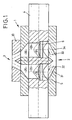
- die sogenannte Produktionsstellung einer Ausführungsform, in
- Fig. 2
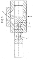
- eine ausgewählte Zwischenstellung beim Verfahren des Siebträgers gemäß Fig. 1 mit Rückspülmöglichkeit, in
- Fig. 3
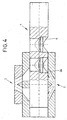
- den Siebwechsel eines Siebes bei der Ausführungsform gemäß Fig. 1, in
- Fig. 4
- den Siebwechsel des anderen Siebes bei der Ausführungsform gemäß Fig. 1 und in
- Fig. 5
- eine Anordnung, bei der zwei Siebträger mit je zwei Sieben übereinander oder nebeneinander angeordnet sind.
- Fig. 1
- the so-called production position of an embodiment, in
- Fig. 2
- a selected intermediate position in the process of the portafilter of FIG. 1 with backwash, in
- Fig. 3
- the screen change of a screen in the embodiment of FIG. 1, in
- Fig. 4
- the screen change of the other screen in the embodiment of FIG. 1 and in
- Fig. 5
- an arrangement in which two filter holders with two screens are arranged one above the other or side by side.
In Fig. 1 ist ein Gehäuse 1 dargestellt, in dem ein Siebträger 4 verschieblich gelagert ist. Das Gehäuse 1 weist einen Zufuhrkanal 2 und einen Abfuhrkanal 3 auf, wobei dem Zufuhrkanal 2 ein Fluid, vorzugsweise verflüssigter Kunststoff, zugeführt wird, wobei dieses Fluid mit Verunreinigungen versehen sein kann, die durch in Siebräumen 7, 8 untergebrachte Filterelemente, die nachfolgend als Siebe 5 und 6 bezeichnet werden, zurückgehalten werden, so daß auf der Reinsiebseite über je einen Austrittskanal 29 gereinigtes Fluid dem Abfuhrkanal 3 zugeführt werden kann. Wie dies die Fig. 1 bis 4 zeigen, schließt der Abfuhrkanal 3 an die Mündungen der Austrittskanäle 29 über Abfuhrteilkanäle 35 und 36 an. An die Austrittsöffnungen des Abfuhrkanales 3 schließen sich nachfolgende Arbeitsaggregate an, wie beispielsweise Strangpressen, Spritzgießmaschinen, Granulatoren od. dgl. Die Mündung des Abfuhrkanales 3 kann dabei in einer Anschlußplatte 30 ausgearbeitet sein.In Fig. 1, a housing 1 is shown, in which a
Der Zufuhrkanal 2 teilt sich von seinem Eingang aus gesehen zum jeweiligen Siebraum 7, 8 in jeweils zwei Zufuhrteilkanäle 31, 32 bzw. 33, 34 auf.The
Insbesondere die Darstellung in Fig. 5, bei der aus einem Siebträger 4 das Sieb 5 entnommen ist, zeigt für den Siebraum 7, daß sich jeder Siebraum zu einem ovalen Austrittskanal 29 verjüngt, wobei die Längsachse dieses Ovals sich in Längsachse des Siebträgers 4 erstreckt und somit langgestreckt ausgebildet ist.In particular, the illustration in Fig. 5, in which the
Fig. 1 läßt erkennen, daß auch die Abfuhrteilkanäle 35, 36 des Abfuhrkanales 3 siebträgerseitig in Längsachse des Siebträgers 4 gesehen langgestreckt ausgebildet sind. Der Abfuhrkanal 3 verjüngt sich aber dann zu seinem freien Ende hin kreisförmig, so daß wie im Stand der Technik kreisförmig ausgebildete Anschlußleitungen für die nachfolgenden Aggregate angeschlossen werden können.Fig. 1 shows that the discharge part of
Bei der Darstellung in Fig. 2 ist erkennbar, daß der Siebträger 4 nach links verschoben ist, um das Sieb 5 dem Siebwechsel zuzuführen. Die Darstellung in Fig. 2 zeigt auch, daß in dieser Zwischenstellung sowohl der Siebraum 7 wie auch der Siebraum 8 noch mit dem Zufuhrkanal 2 verbunden sind, und zwar über die Zufuhrteilkanäle 31, 32 und 33, während der Zufuhrteilkanal 34 durch den eigentlichen Siebträger 4 abgeschlossen ist.In the illustration in Fig. 2 it can be seen that the
Auch bei einem weiteren Verschieben des Siebträgers 4 in die in Fig. 3 dargestellte Stellung - also nach links - verbleibt immer noch das Sieb 6 mit dem Siebraum 8 mit dem Zufuhrkanal 2 über den Zufuhrteilkanal 31 in Verbindung, so daß auch weiterhin gereinigtes Fluid dem Abfuhrkanal 3 zugeführt wird.Even with a further displacement of the
Die Fig. 3 und Fig. 4 zeigen die Stellung für den Siebwechsel des Siebes 5 bzw. 6, und auch hier ist erkennbar, daß nunmehr der Zufuhrkanal 2 über den Zufuhrteilkanal 31 bzw. 34 mit dem Abfuhrkanal 3 in Verbindung steht.FIGS. 3 and 4 show the position for the screen change of the
Durch diese Anordnung wird erreicht, daß keine kurzzeitigen Schwankungen im Prozeßdruck auftreten, die sich nachteilig für die Regelparameter der nachfolgenden Verarbeitungsaggregate auswirken könnte.By this arrangement it is achieved that no brief fluctuations in the process pressure occur, which could adversely affect the control parameters of subsequent processing units.
Bei sehr großen Anlagen ist für das Verschieben des Siebträgers 4 natürlich eine große, leistungsfähige Hydraulikanlage erforderlich und trotzdem ist bei großen Anlagen die Verschiebezeit für den Siebträger relativ lang, wobei durch die erfindungsgemäße Anordnung, insbesondere bei großen Anlagen erreicht wird, daß nunmehr auch bei einem relativ langsamen Verschieben des Siebträgers 4 stets eine Verbindung zwischen dem Zufuhrkanal 2 und dem Abfuhrkanal 3 aufrechterhalten bleibt.For very large systems is of course a large, powerful hydraulic system required for moving the
In Fig. 2 ist als Beispiel eine Rückspülmöglichkeit dargestellt, und zwar mit Rückspülkanälen, die durch Absperreinrichtungen zu öffnen und zu schließen sind.In Fig. 2, a backwash option is shown as an example, with backwash channels, which are to be opened and closed by shut-off devices.
Als besonders wesentlich für die Rückspülung ist hervorzuheben, daß - bevor der Rückspülvorgang beginnt - das rückzuspülende Sieb auf der Rückseite mit erheblichem Druck beaufschlagt werden kann, so daß dadurch der Rückspülvorgang wesentlich erleichtert, beschleunigt und verbessert wird. Gleichzeitig werden geringe Verschiebewege erreicht, was ebenfalls für den Energieaufwand erheblich ist.Particularly important for the backwashing is to emphasize that - before the backwashing process begins - the backwashed sieve on the back can be subjected to considerable pressure, thereby significantly facilitating the backwashing, accelerated and improved. At the same time, low displacement paths are achieved, which is also significant for the energy consumption.
- 11
- Gehäusecasing
- 22
- Zufuhrkanalsupply channel
- 33
- Abfuhrkanaldischarge channel
- 44
- SiebträgerEspresso Machines
- 55
- Siebscree
- 66
- Siebscree
- 77
- Siebraumscreen room
- 88th
- Siebraumscreen room
- 2929
- Austrittskanaloutlet channel
- 3030
- Anbauteilattachment
- 3131
- ZuführteilkanalZuführteilkanal
- 3232
- ZuführteilkanalZuführteilkanal
- 3333
- ZuführteilkanalZuführteilkanal
- 3434
- ZuführteilkanalZuführteilkanal
Claims (6)
- Device for filtering a fluid, in particular a liquefied plastic, with a housing (1), an infeed duct (2) and an outfeed duct (3), where at least two filter elements (5, 6) in appropriate filter compartments (7, 8) in a movably mounted filter carrier (4), are located in the flow path of the fluid at right angles to the direction of flow, and can be brought into contact with the infeed duct (2) and the outfeed duct (3), where each of the filter compartments has an outlet duct (29) machined in the filter carrier (4) at the clean side of the filter, which is aligned towards the outfeed duct (3), and the filter compartments (7, 8) machined in the filter carrier (4) are located behind one another so closely in the direction of movement of the filter carrier (4), that when one filter element (5 or 6) is pushed out of the housing (1) for replacement, a connection between the infeed duct (2) and the outfeed duct (3) is maintained with one filter element (5 or 6) between the ducts, characterised in thata) in the housing (1) the infeed duct (2) divides into two infeed-duct sections (31, 32) and (33, 34) leading to the filter elements (5, 6),b) each of the filter compartments (7, 8) tapers to form an extended outlet duct (29) looking along the lengthwise axis of the filter carrier (4),c) the outfeed duct (3) forms extended outfeed-duct sections (35, 36) on the side of the filter carrier looking along the lengthwise axis of the filter carrier (4), and tapers in circular shape towards its free end.
- Device according to claim 1, characterised in that the outfeed duct (3) is machined in a component (30) which can be connected to the housing (1).
- Device according to claim 1, characterised in that the outlet duct (29) is formed as individual bores arranged in a row.
- Device according to claim 1, characterised in that the outfeed-duct sections (35, 36) are formed as individual recesses arranged in a row.
- Device according to claim 1, characterised in that the infeed duct (2) is machined in a component which can be connected to the housing (1).
- Device according to one of the claims 1 to 5, characterised in that reversible-flow ducts and shut-off devices are provided for these.
Applications Claiming Priority (9)
| Application Number | Priority Date | Filing Date | Title |
|---|---|---|---|
| DE10242993 | 2002-09-17 | ||
| DE10242993 | 2002-09-17 | ||
| DE10254022 | 2002-11-20 | ||
| DE10254022A DE10254022B4 (en) | 2002-09-17 | 2002-11-20 | Device for filtering a fluid, in particular for plastic processing plants |
| DE10308429 | 2003-02-27 | ||
| DE10308429A DE10308429B3 (en) | 2003-02-27 | 2003-02-27 | Filter for molten plastics, at a plastics processing machine, has a sliding sieve carrier which blocks the flow through the housing when withdrawn for a filter change |
| DE2003117170 DE10317170A1 (en) | 2003-03-13 | 2003-04-15 | Filter unit for liquid plastics has filter screen chambers spaced to ensure that when a filter screen carrier is moved transverse to flow a melt connection always exists between feed and take-off lines |
| DE10317170 | 2003-04-15 | ||
| EP03795720A EP1423178B1 (en) | 2002-09-17 | 2003-07-18 | Device for filtering a fluid, especially for plastic-processing installations |
Related Parent Applications (2)
| Application Number | Title | Priority Date | Filing Date |
|---|---|---|---|
| EP03795720.6 Division | 2003-07-18 | ||
| EP03795720A Division EP1423178B1 (en) | 2002-09-17 | 2003-07-18 | Device for filtering a fluid, especially for plastic-processing installations |
Publications (2)
| Publication Number | Publication Date |
|---|---|
| EP1524022A1 EP1524022A1 (en) | 2005-04-20 |
| EP1524022B1 true EP1524022B1 (en) | 2007-02-21 |
Family
ID=40964075
Family Applications (1)
| Application Number | Title | Priority Date | Filing Date |
|---|---|---|---|
| EP04030092A Expired - Lifetime EP1524022B1 (en) | 2002-09-17 | 2003-07-18 | Device for filtering a liquid, especially for plastics processing plants |
Country Status (2)
| Country | Link |
|---|---|
| EP (1) | EP1524022B1 (en) |
| JP (1) | JP4734429B2 (en) |
Families Citing this family (4)
| Publication number | Priority date | Publication date | Assignee | Title |
|---|---|---|---|---|
| WO2010138602A1 (en) * | 2009-05-26 | 2010-12-02 | Polymer Systems, Inc. | Filtration apparatus for filtering a fluid and methods of using the same |
| DE102010029591B4 (en) * | 2010-06-01 | 2012-11-22 | Kreyenborg Verwaltungen Und Beteiligungen Gmbh & Co. Kg | Filter device for high-viscosity media |
| DE102011051373B4 (en) | 2011-06-27 | 2015-06-03 | Nordson Holdings S.À.R.L. & Co. Kg | Filtration device for fluids |
| DE102012100641A1 (en) * | 2011-07-29 | 2013-01-31 | Kreyenborg Verwaltungen Und Beteiligungen Gmbh & Co. Kg | Filter apparatus for large surface filtration of e.g. polyamide, has filter insert pushed into opening by displacement of support element, and closure element inserted into housing bore or at opening of bore when lowering support element |
Family Cites Families (5)
| Publication number | Priority date | Publication date | Assignee | Title |
|---|---|---|---|---|
| DE3527173C1 (en) * | 1985-07-03 | 1986-09-11 | Kreyenborg Verwaltungen und Beteiligungen KG, 4400 Münster | Filter device for extrusion and injection moulding machines |
| JPH07186242A (en) * | 1993-12-27 | 1995-07-25 | Japan Steel Works Ltd:The | Screen pack exchanging apparatus |
| JPH0857938A (en) * | 1994-06-16 | 1996-03-05 | Shiro Tsuchiya | Screen exchange device for plastic extrusion molding machine |
| DE59507639D1 (en) * | 1994-10-19 | 2000-02-24 | Bematec S A | Filter device with backwash |
| JP3604484B2 (en) * | 1995-12-16 | 2004-12-22 | 四郎 土谷 | Fluid screen changer |
-
2003
- 2003-07-18 EP EP04030092A patent/EP1524022B1/en not_active Expired - Lifetime
-
2009
- 2009-01-22 JP JP2009011814A patent/JP4734429B2/en not_active Expired - Fee Related
Also Published As
| Publication number | Publication date |
|---|---|
| EP1524022A1 (en) | 2005-04-20 |
| JP4734429B2 (en) | 2011-07-27 |
| JP2009160935A (en) | 2009-07-23 |
Similar Documents
| Publication | Publication Date | Title |
|---|---|---|
| DE4012404C1 (en) | ||
| WO2004026432A1 (en) | Device for filtering a fluid, especially for plastic-processing installations | |
| EP2836283A1 (en) | Device for filtering a thermoplastic melt | |
| EP1778379B1 (en) | Device and method for filtering a fluid, in particular for plastics processing plants | |
| EP0433587B1 (en) | Screen changer apparatus with cylindrical screens | |
| DE102014016634A1 (en) | Filtration device for filtering a fluid | |
| EP0828598B1 (en) | Filter changing device for plastics processing plants | |
| EP1524022B1 (en) | Device for filtering a liquid, especially for plastics processing plants | |
| DE10254022B4 (en) | Device for filtering a fluid, in particular for plastic processing plants | |
| EP1082205B1 (en) | Filter device for extruders and injection moulding machines | |
| EP0798098B1 (en) | Device for filtering plastic melts | |
| EP2001651B1 (en) | Device for filtering a liquid synthetic material | |
| EP0680815B1 (en) | Filtration device for extrusion presses | |
| EP1762364B1 (en) | Device for filtering a fluid, especially for plastic-processing installations | |
| EP0875357A1 (en) | Filter device for extruders and injection machines | |
| DE4130002C1 (en) | Distribution point for extrusion press and injection, moulding machine - includes housing, supply unit, vertical bolt unit and inlet connection channel | |
| EP1245366B1 (en) | Locking means for controlling the flow of a flowable medium | |
| DE19500060C1 (en) | Filter for thermoplastic extrusion and injection moulding machine | |
| EP0919353A2 (en) | Filter apparatus for a fluid stream and filter module for use in such an apparatus | |
| DE10317170A1 (en) | Filter unit for liquid plastics has filter screen chambers spaced to ensure that when a filter screen carrier is moved transverse to flow a melt connection always exists between feed and take-off lines | |
| DE102004010968B4 (en) | Device for filtering a fluid, in particular a liquefied plastic | |
| DE4126261C1 (en) | Simple and reliable filter arrangement for extrusion presses, etc. - including separate channel sectors between inlet and outlet channels and exchangeable sieve carrier, etc. | |
| DE20321049U1 (en) | Filter unit for liquid plastics has filter screen chambers spaced to ensure that when a filter screen carrier is moved transverse to flow a melt connection always exists between feed and take-off lines | |
| DE10308429B3 (en) | Filter for molten plastics, at a plastics processing machine, has a sliding sieve carrier which blocks the flow through the housing when withdrawn for a filter change | |
| EP2025495B1 (en) | Device for filtering a fluid, in particular a liquefied plastic |
Legal Events
| Date | Code | Title | Description |
|---|---|---|---|
| PUAI | Public reference made under article 153(3) epc to a published international application that has entered the european phase |
Free format text: ORIGINAL CODE: 0009012 |
|
| AC | Divisional application: reference to earlier application |
Ref document number: 1423178 Country of ref document: EP Kind code of ref document: P |
|
| AK | Designated contracting states |
Kind code of ref document: A1 Designated state(s): AT BE BG CH CY CZ DE DK EE ES FI FR GB GR HU IE IT LI LU MC NL PT RO SE SI SK TR |
|
| AX | Request for extension of the european patent |
Extension state: AL LT LV MK |
|
| 17P | Request for examination filed |
Effective date: 20050316 |
|
| AKX | Designation fees paid |
Designated state(s): AT BE BG CH CY CZ DE DK EE ES FI FR GB GR HU IE IT LI LU MC NL PT RO SE SI SK TR |
|
| GRAP | Despatch of communication of intention to grant a patent |
Free format text: ORIGINAL CODE: EPIDOSNIGR1 |
|
| GRAS | Grant fee paid |
Free format text: ORIGINAL CODE: EPIDOSNIGR3 |
|
| GRAA | (expected) grant |
Free format text: ORIGINAL CODE: 0009210 |
|
| AC | Divisional application: reference to earlier application |
Ref document number: 1423178 Country of ref document: EP Kind code of ref document: P |
|
| AK | Designated contracting states |
Kind code of ref document: B1 Designated state(s): AT BE BG CH CY CZ DE DK EE ES FI FR GB GR HU IE IT LI LU MC NL PT RO SE SI SK TR |
|
| PG25 | Lapsed in a contracting state [announced via postgrant information from national office to epo] |
Ref country code: DK Free format text: LAPSE BECAUSE OF FAILURE TO SUBMIT A TRANSLATION OF THE DESCRIPTION OR TO PAY THE FEE WITHIN THE PRESCRIBED TIME-LIMIT Effective date: 20070221 Ref country code: IE Free format text: LAPSE BECAUSE OF FAILURE TO SUBMIT A TRANSLATION OF THE DESCRIPTION OR TO PAY THE FEE WITHIN THE PRESCRIBED TIME-LIMIT Effective date: 20070221 Ref country code: NL Free format text: LAPSE BECAUSE OF FAILURE TO SUBMIT A TRANSLATION OF THE DESCRIPTION OR TO PAY THE FEE WITHIN THE PRESCRIBED TIME-LIMIT Effective date: 20070221 Ref country code: SI Free format text: LAPSE BECAUSE OF FAILURE TO SUBMIT A TRANSLATION OF THE DESCRIPTION OR TO PAY THE FEE WITHIN THE PRESCRIBED TIME-LIMIT Effective date: 20070221 |
|
| REG | Reference to a national code |
Ref country code: GB Ref legal event code: FG4D Free format text: NOT ENGLISH |
|
| REG | Reference to a national code |
Ref country code: CH Ref legal event code: EP |
|
| REF | Corresponds to: |
Ref document number: 50306592 Country of ref document: DE Date of ref document: 20070405 Kind code of ref document: P |
|
| REG | Reference to a national code |
Ref country code: CH Ref legal event code: NV Representative=s name: BRAUNPAT BRAUN EDER AG |
|
| REG | Reference to a national code |
Ref country code: IE Ref legal event code: FG4D Free format text: LANGUAGE OF EP DOCUMENT: GERMAN |
|
| PG25 | Lapsed in a contracting state [announced via postgrant information from national office to epo] |
Ref country code: SE Free format text: LAPSE BECAUSE OF FAILURE TO SUBMIT A TRANSLATION OF THE DESCRIPTION OR TO PAY THE FEE WITHIN THE PRESCRIBED TIME-LIMIT Effective date: 20070521 Ref country code: BG Free format text: LAPSE BECAUSE OF FAILURE TO SUBMIT A TRANSLATION OF THE DESCRIPTION OR TO PAY THE FEE WITHIN THE PRESCRIBED TIME-LIMIT Effective date: 20070521 |
|
| PG25 | Lapsed in a contracting state [announced via postgrant information from national office to epo] |
Ref country code: ES Free format text: LAPSE BECAUSE OF FAILURE TO SUBMIT A TRANSLATION OF THE DESCRIPTION OR TO PAY THE FEE WITHIN THE PRESCRIBED TIME-LIMIT Effective date: 20070601 |
|
| PG25 | Lapsed in a contracting state [announced via postgrant information from national office to epo] |
Ref country code: PT Free format text: LAPSE BECAUSE OF FAILURE TO SUBMIT A TRANSLATION OF THE DESCRIPTION OR TO PAY THE FEE WITHIN THE PRESCRIBED TIME-LIMIT Effective date: 20070723 |
|
| NLV1 | Nl: lapsed or annulled due to failure to fulfill the requirements of art. 29p and 29m of the patents act | ||
| GBV | Gb: ep patent (uk) treated as always having been void in accordance with gb section 77(7)/1977 [no translation filed] |
Effective date: 20070221 |
|
| REG | Reference to a national code |
Ref country code: IE Ref legal event code: FD4D |
|
| EN | Fr: translation not filed | ||
| PG25 | Lapsed in a contracting state [announced via postgrant information from national office to epo] |
Ref country code: GB Free format text: LAPSE BECAUSE OF FAILURE TO SUBMIT A TRANSLATION OF THE DESCRIPTION OR TO PAY THE FEE WITHIN THE PRESCRIBED TIME-LIMIT Effective date: 20070221 Ref country code: SK Free format text: LAPSE BECAUSE OF FAILURE TO SUBMIT A TRANSLATION OF THE DESCRIPTION OR TO PAY THE FEE WITHIN THE PRESCRIBED TIME-LIMIT Effective date: 20070221 |
|
| PLBE | No opposition filed within time limit |
Free format text: ORIGINAL CODE: 0009261 |
|
| STAA | Information on the status of an ep patent application or granted ep patent |
Free format text: STATUS: NO OPPOSITION FILED WITHIN TIME LIMIT |
|
| PG25 | Lapsed in a contracting state [announced via postgrant information from national office to epo] |
Ref country code: CZ Free format text: LAPSE BECAUSE OF FAILURE TO SUBMIT A TRANSLATION OF THE DESCRIPTION OR TO PAY THE FEE WITHIN THE PRESCRIBED TIME-LIMIT Effective date: 20070221 Ref country code: RO Free format text: LAPSE BECAUSE OF FAILURE TO SUBMIT A TRANSLATION OF THE DESCRIPTION OR TO PAY THE FEE WITHIN THE PRESCRIBED TIME-LIMIT Effective date: 20070221 |
|
| 26N | No opposition filed |
Effective date: 20071122 |
|
| BERE | Be: lapsed |
Owner name: KREYENBORG VERWALTUNGEN UND BETEILIGUNGEN G.M.B.H. Effective date: 20070731 |
|
| PG25 | Lapsed in a contracting state [announced via postgrant information from national office to epo] |
Ref country code: FR Free format text: LAPSE BECAUSE OF FAILURE TO SUBMIT A TRANSLATION OF THE DESCRIPTION OR TO PAY THE FEE WITHIN THE PRESCRIBED TIME-LIMIT Effective date: 20071012 Ref country code: GR Free format text: LAPSE BECAUSE OF FAILURE TO SUBMIT A TRANSLATION OF THE DESCRIPTION OR TO PAY THE FEE WITHIN THE PRESCRIBED TIME-LIMIT Effective date: 20070522 |
|
| PG25 | Lapsed in a contracting state [announced via postgrant information from national office to epo] |
Ref country code: BE Free format text: LAPSE BECAUSE OF NON-PAYMENT OF DUE FEES Effective date: 20070731 |
|
| PG25 | Lapsed in a contracting state [announced via postgrant information from national office to epo] |
Ref country code: FR Free format text: LAPSE BECAUSE OF FAILURE TO SUBMIT A TRANSLATION OF THE DESCRIPTION OR TO PAY THE FEE WITHIN THE PRESCRIBED TIME-LIMIT Effective date: 20070221 |
|
| PG25 | Lapsed in a contracting state [announced via postgrant information from national office to epo] |
Ref country code: EE Free format text: LAPSE BECAUSE OF FAILURE TO SUBMIT A TRANSLATION OF THE DESCRIPTION OR TO PAY THE FEE WITHIN THE PRESCRIBED TIME-LIMIT Effective date: 20070221 |
|
| PG25 | Lapsed in a contracting state [announced via postgrant information from national office to epo] |
Ref country code: CY Free format text: LAPSE BECAUSE OF FAILURE TO SUBMIT A TRANSLATION OF THE DESCRIPTION OR TO PAY THE FEE WITHIN THE PRESCRIBED TIME-LIMIT Effective date: 20070221 |
|
| PG25 | Lapsed in a contracting state [announced via postgrant information from national office to epo] |
Ref country code: LU Free format text: LAPSE BECAUSE OF NON-PAYMENT OF DUE FEES Effective date: 20070718 Ref country code: FI Free format text: LAPSE BECAUSE OF FAILURE TO SUBMIT A TRANSLATION OF THE DESCRIPTION OR TO PAY THE FEE WITHIN THE PRESCRIBED TIME-LIMIT Effective date: 20070221 |
|
| PG25 | Lapsed in a contracting state [announced via postgrant information from national office to epo] |
Ref country code: HU Free format text: LAPSE BECAUSE OF FAILURE TO SUBMIT A TRANSLATION OF THE DESCRIPTION OR TO PAY THE FEE WITHIN THE PRESCRIBED TIME-LIMIT Effective date: 20070822 Ref country code: TR Free format text: LAPSE BECAUSE OF FAILURE TO SUBMIT A TRANSLATION OF THE DESCRIPTION OR TO PAY THE FEE WITHIN THE PRESCRIBED TIME-LIMIT Effective date: 20070221 |
|
| PG25 | Lapsed in a contracting state [announced via postgrant information from national office to epo] |
Ref country code: MC Free format text: LAPSE BECAUSE OF NON-PAYMENT OF DUE FEES Effective date: 20070731 |
|
| REG | Reference to a national code |
Ref country code: DE Ref legal event code: R082 Ref document number: 50306592 Country of ref document: DE Representative=s name: HABBEL & HABBEL, DE |
|
| REG | Reference to a national code |
Ref country code: CH Ref legal event code: PUE Owner name: NORDSON HOLDINGS S.A.R.L. AND CO. KG, DE Free format text: FORMER OWNER: KREYENBORG VERWALTUNGEN UND BETEILIGUNGEN GMBH AND CO. KG, DE |
|
| REG | Reference to a national code |
Ref country code: DE Ref legal event code: R081 Ref document number: 50306592 Country of ref document: DE Owner name: NORDSON HOLDINGS S.A.R.L. & CO. KG, DE Free format text: FORMER OWNER: KREYENBORG VERWALTUNGEN UND BETEILIGUNGEN GMBH & CO. KG, 48157 MUENSTER, DE Effective date: 20140917 Ref country code: DE Ref legal event code: R082 Ref document number: 50306592 Country of ref document: DE Representative=s name: HABBEL & HABBEL, DE Effective date: 20140917 Ref country code: DE Ref legal event code: R082 Ref document number: 50306592 Country of ref document: DE Representative=s name: EISENFUEHR SPEISER PATENTANWAELTE RECHTSANWAEL, DE Effective date: 20140917 |
|
| REG | Reference to a national code |
Ref country code: AT Ref legal event code: PC Ref document number: 354414 Country of ref document: AT Kind code of ref document: T Owner name: NORDSON HOLDINGS S.A.R.L. & CO. KG, DE Effective date: 20150618 |
|
| REG | Reference to a national code |
Ref country code: DE Ref legal event code: R082 Ref document number: 50306592 Country of ref document: DE Representative=s name: EISENFUEHR SPEISER PATENTANWAELTE RECHTSANWAEL, DE |
|
| REG | Reference to a national code |
Ref country code: CH Ref legal event code: PCAR Free format text: NEW ADDRESS: HOLEESTRASSE 87, 4054 BASEL (CH) |
|
| PGFP | Annual fee paid to national office [announced via postgrant information from national office to epo] |
Ref country code: IT Payment date: 20220726 Year of fee payment: 20 Ref country code: DE Payment date: 20220720 Year of fee payment: 20 Ref country code: AT Payment date: 20220721 Year of fee payment: 20 |
|
| PGFP | Annual fee paid to national office [announced via postgrant information from national office to epo] |
Ref country code: CH Payment date: 20220725 Year of fee payment: 20 |
|
| P01 | Opt-out of the competence of the unified patent court (upc) registered |
Effective date: 20230530 |
|
| REG | Reference to a national code |
Ref country code: DE Ref legal event code: R071 Ref document number: 50306592 Country of ref document: DE |
|
| REG | Reference to a national code |
Ref country code: CH Ref legal event code: PL |
|
| REG | Reference to a national code |
Ref country code: AT Ref legal event code: MK07 Ref document number: 354414 Country of ref document: AT Kind code of ref document: T Effective date: 20230718 |