EP1245326A1 - Verfahren zum Betreiben einer Lasergravureinrichtung - Google Patents
Verfahren zum Betreiben einer Lasergravureinrichtung Download PDFInfo
- Publication number
- EP1245326A1 EP1245326A1 EP02007001A EP02007001A EP1245326A1 EP 1245326 A1 EP1245326 A1 EP 1245326A1 EP 02007001 A EP02007001 A EP 02007001A EP 02007001 A EP02007001 A EP 02007001A EP 1245326 A1 EP1245326 A1 EP 1245326A1
- Authority
- EP
- European Patent Office
- Prior art keywords
- modulator
- laser beam
- laser
- fpn
- focus
- Prior art date
- Legal status (The legal status is an assumption and is not a legal conclusion. Google has not performed a legal analysis and makes no representation as to the accuracy of the status listed.)
- Granted
Links
- 238000000034 method Methods 0.000 title claims description 37
- 238000010147 laser engraving Methods 0.000 title claims description 29
- 239000011159 matrix material Substances 0.000 claims description 33
- 238000004049 embossing Methods 0.000 claims description 32
- 239000006096 absorbing agent Substances 0.000 claims description 17
- 238000009826 distribution Methods 0.000 claims description 8
- 230000006978 adaptation Effects 0.000 claims description 6
- 230000001419 dependent effect Effects 0.000 claims description 6
- 239000013078 crystal Substances 0.000 claims description 5
- 230000001360 synchronised effect Effects 0.000 claims description 3
- 238000007493 shaping process Methods 0.000 claims 1
- 238000011017 operating method Methods 0.000 abstract 1
- 230000008901 benefit Effects 0.000 description 4
- 230000008859 change Effects 0.000 description 4
- 230000008569 process Effects 0.000 description 4
- 238000012545 processing Methods 0.000 description 4
- 238000012937 correction Methods 0.000 description 3
- 238000013461 design Methods 0.000 description 2
- 238000011161 development Methods 0.000 description 2
- 230000000694 effects Effects 0.000 description 2
- 230000007257 malfunction Effects 0.000 description 2
- 230000003287 optical effect Effects 0.000 description 2
- 230000005855 radiation Effects 0.000 description 2
- 125000002066 L-histidyl group Chemical group [H]N1C([H])=NC(C([H])([H])[C@](C(=O)[*])([H])N([H])[H])=C1[H] 0.000 description 1
- 229910000831 Steel Inorganic materials 0.000 description 1
- 238000002679 ablation Methods 0.000 description 1
- 230000001133 acceleration Effects 0.000 description 1
- 230000007423 decrease Effects 0.000 description 1
- 230000008030 elimination Effects 0.000 description 1
- 238000003379 elimination reaction Methods 0.000 description 1
- 238000002474 experimental method Methods 0.000 description 1
- 239000000835 fiber Substances 0.000 description 1
- 230000006870 function Effects 0.000 description 1
- 230000002452 interceptive effect Effects 0.000 description 1
- 238000003754 machining Methods 0.000 description 1
- 238000004519 manufacturing process Methods 0.000 description 1
- 239000006223 plastic coating Substances 0.000 description 1
- 230000009467 reduction Effects 0.000 description 1
- 238000000926 separation method Methods 0.000 description 1
- 238000004904 shortening Methods 0.000 description 1
- 239000010959 steel Substances 0.000 description 1
- 238000012546 transfer Methods 0.000 description 1
Images

Classifications
-
- B—PERFORMING OPERATIONS; TRANSPORTING
- B41—PRINTING; LINING MACHINES; TYPEWRITERS; STAMPS
- B41C—PROCESSES FOR THE MANUFACTURE OR REPRODUCTION OF PRINTING SURFACES
- B41C1/00—Forme preparation
- B41C1/02—Engraving; Heads therefor
- B41C1/04—Engraving; Heads therefor using heads controlled by an electric information signal
- B41C1/05—Heat-generating engraving heads, e.g. laser beam, electron beam
-
- B—PERFORMING OPERATIONS; TRANSPORTING
- B23—MACHINE TOOLS; METAL-WORKING NOT OTHERWISE PROVIDED FOR
- B23K—SOLDERING OR UNSOLDERING; WELDING; CLADDING OR PLATING BY SOLDERING OR WELDING; CUTTING BY APPLYING HEAT LOCALLY, e.g. FLAME CUTTING; WORKING BY LASER BEAM
- B23K26/00—Working by laser beam, e.g. welding, cutting or boring
- B23K26/02—Positioning or observing the workpiece, e.g. with respect to the point of impact; Aligning, aiming or focusing the laser beam
- B23K26/06—Shaping the laser beam, e.g. by masks or multi-focusing
- B23K26/064—Shaping the laser beam, e.g. by masks or multi-focusing by means of optical elements, e.g. lenses, mirrors or prisms
-
- B—PERFORMING OPERATIONS; TRANSPORTING
- B23—MACHINE TOOLS; METAL-WORKING NOT OTHERWISE PROVIDED FOR
- B23K—SOLDERING OR UNSOLDERING; WELDING; CLADDING OR PLATING BY SOLDERING OR WELDING; CUTTING BY APPLYING HEAT LOCALLY, e.g. FLAME CUTTING; WORKING BY LASER BEAM
- B23K26/00—Working by laser beam, e.g. welding, cutting or boring
- B23K26/02—Positioning or observing the workpiece, e.g. with respect to the point of impact; Aligning, aiming or focusing the laser beam
- B23K26/06—Shaping the laser beam, e.g. by masks or multi-focusing
- B23K26/0665—Shaping the laser beam, e.g. by masks or multi-focusing by beam condensation on the workpiece, e.g. for focusing
-
- B—PERFORMING OPERATIONS; TRANSPORTING
- B23—MACHINE TOOLS; METAL-WORKING NOT OTHERWISE PROVIDED FOR
- B23K—SOLDERING OR UNSOLDERING; WELDING; CLADDING OR PLATING BY SOLDERING OR WELDING; CUTTING BY APPLYING HEAT LOCALLY, e.g. FLAME CUTTING; WORKING BY LASER BEAM
- B23K26/00—Working by laser beam, e.g. welding, cutting or boring
- B23K26/36—Removing material
- B23K26/361—Removing material for deburring or mechanical trimming
Definitions
- the present invention relates to a method for Operation of a laser engraving device for the engraving of Printing or embossing forms, with a laser, with a one first modulation frequency generating frequency generator and with one after the laser, with the first Modulation frequency feedable acousto-optical modulator for frequency-dependent laser beam deflection and distribution, a laser beam path from the modulator in passes an absorber and a second laser beam path an adaptation optics forming the laser beam and by a focusing optics focusing the laser beam into one Focus point on the surface of the engraving Printing or embossing form leads.
- a laser engraving device based on the above The method is operable is known from WO 97/19783.
- This document describes a laser engraving system for engraving a workpiece surface with a laser beam source, one in the beam path of the laser beam source lying modulator, one downstream of the modulator Optics arranged at a distance from the workpiece surface is, with optics and workpiece relative to each other are moved, and a control device, the modulator driven with a control signal so that its on output radiation hitting the workpiece surface is modulated in accordance with the control signal and the Workpiece surface machined accordingly deep.
- the workpiece can be, for example, a roller a rubber or plastic coating.
- Farther is a second in this known laser engraving system Laser beam source provided by the control device is controlled with a second control signal.
- the fine structures in the workpiece surface should profile to be generated from that via the modulator guided first laser beam are formed during the Depth areas of the profile from the laser beam of the second Lasers are to be formed.
- the modulator on the one hand and the second laser beam source on the other of interrelated but separate Control signals controlled.
- the two perpendicular to each other polarized laser beams from the modulator on the one hand and the second laser beam source on the other are transmitted by a selective mirror or reflected and together via optics on the one to be processed Workpiece surface guided.
- This laser engraving device shows the Technical effort relatively high because two lasers are used Need to become. In addition, this laser engraving machine is only Can be used economically if particularly large engraving depths should be achieved with the use of a single Lasers cannot be achieved.
- a method is known from EP 1 068 923 with which the intensity distribution in a laser engraving device the laser beam in the focus point can be changed quickly.
- at least two partial beams with different Intensity distribution used that at a Working beam can be merged.
- the intensity of the partial beams can be changed individually, can the intensity distribution within the focus point of the merged laser beam in the desired manner changed and adapted to different applications become.
- This can be used in the manufacture of printing cylinders for example the shape of gravure cells are advantageously influenced in the printing form surface, however, this does not accelerate the engraving reached.
- the object of the present invention is to create a process of the type mentioned at the beginning with a clear one with the least possible technical effort Acceleration of the engraving can be achieved.
- a relative little additional technical effort namely the additional simultaneous generation and feeding at least one further modulation frequency in the acousto-optical Modulator, at least one other focus point created on the surface of the printing or embossing mold.
- the engraving time to be used is halved, since it is now parallel to each other two points on the surface of the Printing or embossing form can be processed simultaneously.
- Corresponding further reductions in the engraving time predefined surface to be engraved can be replaced by further Increase the focus points according to the described Principle can be achieved.
- the acousto-optical modulator also at simultaneous feeding of two or more different ones Modulation frequencies the desired function, namely the frequency-dependent beam deflection, without being prone to malfunction or damage.
- the complex and expensive use of your own laser for each individual laser beam is in the invention Procedure no longer required.
- a first development of the method provides that the modulation frequencies are variable and based on a desired frequency can be set. So that exists the possibility by choosing the modulation frequencies and their frequency spacing the angle the deflection of the to the surface of the printing or embossing leading laser beam paths absolutely and relative to each other to influence, so that both the Location as well as the distance of the generated focus points relative can be influenced to one another in the desired manner. By the frequency spacing or difference of the modulation frequencies becomes the difference in laser beam deflection on the different laser beam paths and thereby the distance between the focal points is determined.
- Modulation frequency (s) each generates a frequency and the acousto-optical modulator is supplied, which itself so different from the first modulation frequency that the focal points generated are lateral relative to each other Take a distance, the one engraving feed at one corresponds to individual focus point.
- the processing speed is doubled, the ones required on the control side Changes in this variant of the method in particular are simple, because the only difference is that two adjacent tracks are not one after the other but processed parallel to each other at the same time become.
- the ones required for this change Measures within tax programs for the Control of the procedure and operation the laser engraving device are limited, so that only a limited effort is required here, which is characterized by the at least doubled processing speed amortized in a short time with the engraving.
- the frequency spacings between two adjacent modulation frequencies are the same. This gives the generated focus points within the range of focus they have formed even distance between them, what for the engraving of engraving points arranged in a regular grid is advantageous and expedient.
- Another embodiment of the invention provides that either a constant power laser with a downstream one first acousto-optical modulator as a power modulator for modulating the laser beam power or a sufficiently fast switchable laser under Elimination of the absorber is used and that a downstream, on the first modulator or switchable laser synchronously tuned (second) acousto-optical Modulator as a deflector for dividing the power modulated Laser beam on the at least two further laser beam paths is used, the first Modulator or the switchable laser only a basic modulation frequency is supplied and which as the deflector serving (second) modulator at least the first Modulation frequency or the first and further modulation frequencies be fed.
- This configuration offers the specific advantage that the power modulation on the one hand and the division into the different ones leading to the surface to be engraved Laser beam paths on the other hand optimized for themselves can be, because here these processes in different Components of the engraving device run off. hereby higher engraving quality can be achieved.
- this can be used as a deflector serving (second) modulator another, as a second Deflector-serving acousto-optical modulator with one relative to the first deflector about its longitudinal central axis, preferably connected by 90 °, rotated alignment the modulator serving as the second deflector at least a first modulation frequency or the first and further modulation frequencies are supplied are formed, whereby at least four laser beam paths are formed that have at least four a two-dimensional focus matrix forming focal points on the surface of the Lead printing or embossing form.
- the focus matrix can usually be round or square Beam passage area of the adjustment and focusing optics better used in terms of area, so that smaller ones Beam passage areas are sufficient than with a longer one one dimensional focus series with equal number of Focus points. It also creates the opportunity either one engraving point in succession with two laser beams to engrave - or the printing or embossing form to make the engraving rotate at a higher speed, since there are now several adjacent to the shape in the circumferential direction Engraving points can be edited simultaneously can.
- the invention proposes that the modulator or that used as a deflector (second) modulator or the two used as deflectors Modulators around his / her longitudinal central axis predeterminable angle is / are rotated, whereby the Arrangement of the emerging laser beam paths and a through whose focus points on the surface of the engraving Print series or embossing form formed focus series or focus matrix undergoes a corresponding rotation by this angle.
- the lateral corresponds Distance the distance between the focus points; at 90 ° the lateral distance is zero, because then the focus points on one or more circumferentially, so Lines running perpendicular to the lateral direction.
- the lateral focus point distance slightly changed and at a predetermined grid spacing be adapted to the engraving to be created.
- the one there necessarily at the same time in the circumferential direction of the mold Any shifting of the focus points is compensated for by corresponding Correction parameters taken into account in the control software and corrected.
- An alternative method implementation for generating a The focus matrix is that at least two in one generated parallel laser beams and introduced in parallel in the acousto-optical modulator and that the acousto-optical modulator is aligned is that in it every laser beam entering at least two each rotated in one to the first level, preferably perpendicular to the first plane, second Flat lying laser beams is split, which at least four laser beam paths are formed, which too at least four forming a two-dimensional focus matrix Focus points on the surface of the print or Lead embossing form. In this way, too, they continue Advantages of the focus matrix already mentioned above.
- the laser can at least the aforementioned two laser beams entering the modulator by a laser with at least one downstream Beam splitter or generated by at least two lasers become.
- the use of two or more lasers increases the effort, but allows the generation much higher Total laser powers, the power of each laser but always divided into several laser beam paths becomes.
- the focus points on the shape is intended to allow that the beam splitter and the modulator or the at least two lasers and the modulator about the longitudinal central axis of the modulator in synchronism with a predefinable one Angle are twisted, causing the arrangement of the from the Modulator emerging laser beam paths and through them Focus points on the surface of the engraving A corresponding focus matrix formed in the printing or embossing form Experience twisting by this angle.
- the effort for rotating the focus matrix is relative low and the rotation is without problems with the necessary Accuracy feasible.
- the beam splitter (s) and the modulator or the at least two lasers and the modulator the existing one Adjustment optics or an additional adjustment optics for the twisting of the arrangement of the laser beam paths and the Focus matrix is used.
- one embodiment preferably provides that all to the focus points on the surface of the Printing or embossing form run through laser beam paths the same adjustment optics and through the same focusing optics be performed.
- This common management of the laser beam paths is advantageous because it does not result in any additional Adjustment and focusing optics are required. From a technical point of view, this joint tour does not constitute Problem because of that in one or two dimensions existing distances between the laser beam paths are so small that a single adjustment lens and focusing optics can be used without it Shadowing from individual laser beam paths comes.
- this joint tour does not constitute Problem because of that in one or two dimensions existing distances between the laser beam paths are so small that a single adjustment lens and focusing optics can be used without it Shadowing from individual laser beam paths comes.
- the retrofit in this way with little effort existing laser engraving equipment possible there are no further adjustment optics and focusing optics are additionally required.
- the existing laser engraving device Interfering with the sensitive optical system of adjustment and focusing optics the existing laser engraving device is then not required.
- the changes can even on the electronic part of the facility, in particular on those for the generation of the modulation frequencies as well as for the transfer of engraving control data from a data memory to the modulation frequency generator responsible parts of the facility.
- a group adjustment lens to the focal points on the surface of the print or Embossing shape running laser beam paths at least for Part by individual adjustment optics or line or summarized in columns by a group adjustment lens be performed.
- the individual Adjustment optics or the group adjustment optics alone or in combination with a common adjustment optics can be used.
- the Use one or more group fitting optics is particularly useful when using modulators with two or more modulation sound fields advantageous because here a strong lateral separation of the laser beam paths is present. It can then be the intensity distribution of the laser radiation each row or column of focus points adapted to each need and thus optimized.
- the ablation geometry of the individual focus point line or column are set so that the Intensity distribution of the overall focus matrix is completely variable is. This allows the lateral as well as the transverse Removal geometry to be removed on the mold surface Areas of the shape can be adapted.
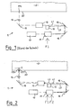
- FIG. 1 of the drawing shows a laser engraving device 1 according to the known prior art. Furthermore, is above 1 a section of a printing or embossing mold 2 shown, which has a cylindrical shape here and about its longitudinal central axis is rotatably clamped. Between the laser engraving device 1 and form 2 takes place during processing a relative movement in the lateral direction, i.e. in Axial direction of the form 2, so that with simultaneous rotation the form 2 around itself gradually the surface 20 of Form 2 can be edited.
- the laser engraving device 1 comprises a laser 10, for example a solid-state or gas laser, such as rod, fiber, Disk, slab or diode lasers.
- the laser 10 The laser beam generated is connected downstream of the laser 10 acousto-optical modulator 11 supplied.
- a modulation frequency F1 fed, for example, by a high frequency signal generator is generated and for example in a frequency range between about 50 and 100 MHz and is amplitude modulated.
- This acousto-optical modulator 11 provides in a known manner for one of the fed Modulation frequency F1 dependent deflection of the Laser beam and thus for splitting into two laser beam paths L0 and L1.
- an absorber 12 is arranged so that the first Laser beam path L0 in the absorber 12 runs while the second laser beam path L1 leads past the absorber 12.
- the absorber 12 is the incident, the laser beam path L0 taking laser beam is absorbed, i.e. converted into heat and dissipated.
- the absorber 12 is for example designed as a water-cooled body to the to be able to dissipate heat energy.
- the other laser beam path L1 leads past the absorber 12 through a matching lens 13 and a focusing lens 14 to a focal point FP1 on the surface 20 of the surface to be engraved Printing or embossing form 2.
- FIG. 2 of the drawing shows a first embodiment of a Laser engraving device 1, which according to the above Method according to the invention is operable. in principle is largely the laser engraving device 1 in Figure 2 with the laser engraving device 1 according to FIG. 1 constructed in accordance; the main difference here consists in the fact that in the device 1 according to FIG 2 the acousto-optical modulator 11 at the same time two different modulation frequencies F1 and F2 fed by a common or by two separate frequency generators, not specifically are shown. As a result, the Laser 10 coming laser beam in the modulator 11 now on divided a total of three laser beam paths L0, L1 and L2, each with a different deflection angle be generated. As previously described, the be fathered.
- the laser beam path leads L0 in the absorber 12; the other two Laser beam paths L1 and L2 lead past the absorber 12 through the same adjustment optics 13 and the same focusing optics 14 to the surface 20 of the printing or embossing mold 2.
- Each laser beam path L1, L2 ends on the surface 20 of form 2 each in its own focus point FP1, FP2.
- These two focal points FP1, FP2 have a lateral one Distance v from each other. This distance is useful v by choosing an appropriate frequency difference of the two modulation frequencies set so that the engraving feed when using an engraving device with just a single focus point.
- FIG Difference from the prior art, two at the same time immediately adjacent parallel tracks of the print or Embossing mold 2 processed. This doubles the Machining speed without the speed of the Rotation of the printing or embossing mold 2 must be increased.
- the two modulation frequencies F1, F2 can each be modulated by themselves so that the two on the laser beam paths L1, L2 running laser beams also one received separate intensity control. '
- the modulation takes place in accordance with stored engraving data, like this is known per se from the prior art, and here but no longer the engraving data for all tracks individually sequentially accessed and for the modulation of a single one Modulation frequency are made available, but rather the engraving data for two parallel tracks accessed simultaneously in parallel and for modulation of the two modulation frequencies provided and the modulation inputs of the frequency generator or Frequency generators are supplied.
- the lateral distance v between the two focus points FP1, FP2 can be varied by varying the frequency difference of the first Modulation frequency F1 and the second modulation frequency.
- F2 can be set because the deflection angle, which is in Modulator 11 is generated, is frequency dependent.
- the distance v can be precisely matched to the respective engraving feed from track to track so that the Engraving device easily to different engraving resolutions, that have different track spacings, adaptable is.
- Modulation frequencies F1, F2 in addition the modulator 11 also more than two modulation frequencies be fed in, whereby an even further division of the laser beam coming from the laser 10 in even more laser beam paths he follows. This is how an increase in Laser beam paths achieve what is called a corresponding further shortening the time required for a given one Engraving of a printing or embossing form leads.
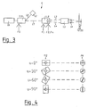
- Figure 3 shows a second embodiment of the laser engraving device 1, with the one to be engraved on the surface 20
- Form multiple focus points in the form of a focus series FR can be generated.
- the laser 10 is also here first created a single laser beam. That laser beam is introduced into the modulator 11.1, in the a basic modulation frequency F0 is fed in simultaneously becomes. Two laser beam paths leave the modulator 11.1 L0 and L1.
- the laser beam path L0 leads into the Absorber 12.
- the laser beam path L1 leads to a second one acousto-optical modulator 11.2, in which at least one Modulation frequency F1, but preferably several modulation frequencies F1, F2 to Fn can be fed.
- any additionally fed modulation frequency F2 to Fn results in an additional laser beam path.
- the Laser beam paths L1 to Ln run through a common one Adjustment optics 13 and focusing optics 14 and then hit in one focus point each, which together form a focus series Form FR on the surface 20 of the to be engraved Shape.
- F1 to Fn have the same frequency spacing from each other, arises between the focus points of the focus series FR on the surface 20 a uniform one Distance from The total focus row then has a length (n - 1) * v.
- this modulator 11.2 As on the second modulator 11.2 by an arrow is indicated, this modulator 11.2 to its Longitudinal central axis that coincides with the axis of the incident laser beam L1 coincides, be twisted. This twist has a twisting of the laser beam paths L1 to Ln and thus also the focus series FR.
- the second modulator 11.2 To achieve the twisted position of the FR focus series it is only necessary to use the second modulator 11.2 to twist its longitudinal central axis.
- the laser 10, the first modulator 11.1 and the absorber 12 can change their position maintain what the execution of the twist very easy makes.
- Engraving device 1 also that the first acousto-optical Modulator 11.1 only as an optical switch serves the power of the straight laser beam path L1 modulated.
- FIG. 5 shows the focus row FR, that in FIG. 4 on the right is drawn at the top, in an enlarged view.
- Figure 5 illustrates that in the present
- the focus points FP1, FP2 to FPn run Focus row FR in the lateral direction L of the surface 20. Der Distance v between two measured in the lateral direction L. Focus points FP1, FP2 and their absolute distance w agree in this position of the focus series FR.
- the absolute distance w between two adjacent focus points FP1, FP2 is at the twist remained unchanged; has changed but depending on the angle u the laterally measured Distance v between two focus points FP1, FP2.
- a due to a given grid spacing of the engraving Desired lateral distance v between two neighboring ones Focus points FP1, FP2 can thus be adjusted a suitable angle u achieved in the desired manner become.
- Emigration of focus points FP1, FP2 etc. up and down, i.e. in the circumferential direction of the surface 20 of the form 2 to be engraved, can by appropriate Corrections in the control programs for the control the device 1 are corrected.
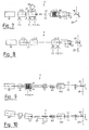
- Figure 7 and Figure 8 show a schematic plan view and side view of another embodiment of the engraving device 1, where it is essential that they are not creates a one-dimensional focus row, but one two-dimensional focus matrix FM.
- the engraving device 1 has a total of three acousto-optical modulators 11.1, 11.2 and 11.3. To generate an output laser beam here again the laser 10 is used The laser beam generated first reaches the first acousto-optical modulator 11.1, in the same one Basic modulation frequency F0 is fed.
- This modulator 11.2 ensures a division in a known manner in two laser beam paths L0 and L1, of which path L0 in the absorber 12 and the path L1 in the second modulator 11.2 leads.
- the second modulator 11.2 at least a further modulation frequency F1, in the present example several modulation frequencies F1, F2 to Fn, fed in, those for a split into a corresponding number Provide laser beam paths L1 to Ln.
- the so generated first modulator 11.2 leaving laser beam paths L1 to Ln run in the third modulator 11.3.
- This third acousto-optical modulator 11.3 is designed so that it two separate modulation fields A1 and A2 having.
- the third modulator 11.3 is regarding its crystal alignment with the second Modulator 11.2 about its longitudinal central axis in the present Example rotated by 90 °.
- the third modulator 11.3 a division of the laser beam paths L1 to Ln in one plane that does here perpendicular to the division plane of the second modulator 11.2 lies.
- laser steel paths L1 to Ln which in two dimensions run parallel to each other.
- All laser beam paths L1 to Ln run behind the third Modulator 11.3 through a common adjustment optics 13 and a common focusing optics 14 and end in one Focus matrix FM on the surface 20 of the to be engraved Shape.
- the focus points within the focus matrix FM have one Distance w from each other.
- Figure 8 shows the engraving device 1 of Figure 7 in the Side view showing the division of the laser beam paths is clear from the third modulator 11.3.
- FIGS 7 and 8 also show that the second modulator 11.2 Modulation frequencies F1, F2 to Fn supplied become.
- the third modulator 11.3 has modulation frequencies F1 ', F2' to Fn 'supplied. These modulation frequencies F1, F1 '; F2, F2 'etc. can each be the same or be different depending on the desired angle of deflection and depending on the desired distance between the individual focal points in the lateral direction and in the circumferential direction the surface 20 of the shape to be engraved.
- the number of focus points created here within the focus matrix as well as their distribution in the lateral and circumferential direction depend on the number of different modulation frequencies fed into the modulators 11.2 and 11.3.
- FIGS. 9 and 10 show a further embodiment of the Engraving device 1, wherein Figure 9 is a side view and Figure 10 is a top view.
- a single laser 10 generates a laser beam which here first in a downstream beam splitter 16 runs where the laser beam turns into two parallel laser beams is divided.
- the two kick in Beam splitters 16 generated laser beams parallel to each other into the acousto-optical modulator 11.
- This modulator 11 corresponds to the third in its execution acousto-optical modulator 11.3 of the engraving device 1 according to FIGS. 7 and 8.
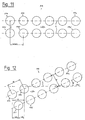
- FIG. 11 An example of a two-dimensional focus matrix FM is in an enlarged representation in FIG. 11 and in FIG. 12 shown, such a focus matrix FM with a Engraving device 1 according to FIGS. 7 and 8 or according to Figures 9 and 10 can be generated.
- FIG. 11 shows the focus matrix in an orientation of the two rows of focus points FP1, FP2 to FPn as well FP1 ', FP2' to FPn 'parallel to the lateral direction L Surface 20 of the shape to be engraved.
- the focus points FP1 to FPn ' form a rectangular arrangement a total of twelve focus points; other numbers and orders focus points are of course possible.
- the lateral distance v is equal to the absolute Distance w within a row.
- FIG. 12 finally shows the focus matrix FM from FIG 11 in an angle relative to the lateral direction L. u twisted position.
- This twisted position of the focus matrix FM can be generated, for example, by synchronous rotation of the second and third modulators 11.2, 11.3 the engraving device 1 according to FIGS. 7 and 8 or by a synchronous rotation of the entire engraving device 1 according to Figures 9 and 10.
- the adjustment optics 13 or a special one additional intended for twisting in the drawings further adjustment optics, not shown, are used become.
- the rotation of the focus matrix FM by the angle u leads to the fact that within each row of focus points FP1 to FPn and FP1 'to FPn' the lateral distance v decreases as already explained above using a single focus series.
- the lateral matrix can also be used with a focus matrix Distance v between two neighboring focus points Desired can be adjusted by a suitable angle u is selected for the rotation. In the example it is Angle of rotation u just chosen so that the lateral distance between two adjacent focus points FP1, FP1 '; FP1 ' FP2 etc. of two different rows exactly half of the lateral distance v between two adjacent focus points FP1, FP2; FP1 ', FP2' etc. within a row equivalent.
- the engraving device 1 and the method for Operation of the engraving device 1 has become clear, the engraving speed when engraving the surface 20 of a form 2 to be engraved increased considerably become.
- the engraving time can be a twelfth of the original engraving time with a single one Reduce focus point.
- the modulators are in the Position, one when feeding in several modulation frequencies Division into more than two laser beam paths. However, the performance of the modulators bumps at a specific modulation frequency fed in and the laser power to be processed dependent load to a limit.
Landscapes
- Physics & Mathematics (AREA)
- Engineering & Computer Science (AREA)
- Optics & Photonics (AREA)
- Plasma & Fusion (AREA)
- Mechanical Engineering (AREA)
- Manufacturing & Machinery (AREA)
- Laser Beam Processing (AREA)
- Manufacture Or Reproduction Of Printing Formes (AREA)
- Lasers (AREA)
Abstract
Description
- daß mindestens eine sich von der ersten Modulationsfrequenz unterscheidende weitere Modulationsfrequenz erzeugt und dem akusto-optischen Modulator neben der ersten Modulationsfrequenz gleichzeitig zugeführt wird,
- daß dadurch der Laserstrahl im akusto-optischen Modulator neben einer ersten Ablenkung mindestens eine sich winkelmäßig von der ersten unterscheidende weitere Ablenkung und dadurch eine weitere Aufteilung erfährt und
- daß so mindestens ein weiterer Laserstrahlweg gebildet wird, der zu mindestens einem weiteren Fokuspunkt ebenfalls auf der Oberfläche der Druck- oder Prägeform führt.
- Figur 1
- eine Lasergravureinrichtung gemäß dem Stand der Technik in schematischer Darstellung,
- Figur 2
- eine Lasergravureinrichtung gemäß Erfindung in einer ersten Ausführung, ebenfalls in schematischer Darstellung,
- Figur 3
- eine Lasergravureinrichtung in einer zweiten Ausführung, wieder in schematischer Darstellung,
- Figur 4
- einen Modulator als Teil der Einrichtung aus Figur 3 in unterschiedlich gedrehten Lagen zusammen mit einer dadurch jeweils erzeugten Fokusreihe,
- Figur 5
- die obere Fokusreihe gemäß Figur 4 in einer vergrößerten Darstellung,
- Figur 6
- die zweite Fokusreihe aus Figur 4, ebenfalls in vergrößerter Darstellung,
- Figur 7
- die Lasergravureinrichtung in einer dritten Ausführung in einer schematischen Draufsicht,
- Figur 8
- die Einrichtung aus Figur 7 in einer schematischen Seitenansicht,
- Figur 9
- die Lasergravureinrichtung in einer vierten Ausführung in einer schematischen Seitenansicht,
- Figur 10
- die Einrichtung aus Figur 9 in einer schematischen Draufsicht,
- Figur 11
- eine mit der Gravureinrichtung gemäß Figur 7 und 8 oder gemäß Figur 9 und 10 erzeugte Fokusmatrix in Draufsicht und
- Figur 12
- die Fokusmatrix aus Figur 11 nach einer Drehung, ebenfalls in Draufsicht.
Claims (17)
- Verfahren zum Betreiben einer Lasergravureinrichtung (1) für die Gravur von Druck- oder Prägeformen (2), mit einem Laser (10), mit einem eine erste Modulationsfrequenz (F1) erzeugenden Frequenzgenerator und mit einem dem Laser (10) nachgeordneten, mit der ersten Modulationsfrequenz (F1) speisbaren akusto-optischen Modulator (11) zur frequenzabhängigen Laserstrahlablenkung und -aufteilung, wobei von dem Modulator (11) aus ein Laserstrahlweg (L0) in einen Absorber (12) führt und ein zweiter Laserstrahlweg (L1) durch eine den Laserstrahl formende Anpassungsoptik (13) und durch eine den Laserstrahl fokussierende Fokussieroptik (14) zu einem Fokuspunkt (FP1) auf der Oberfläche (20) der zu gravierenden Druck- oder Prägeform (2) führt,
dadurch gekennzeichnet,daß mindestens eine sich von der ersten Modulationsfrequenz (F1) unterscheidende weitere Modulationsfrequenz (F2) erzeugt und dem akusto-optischen Modulator (11) neben der ersten Modulationsfrequenz (F1) gleichzeitig zugeführt wird,daß dadurch der Laserstrahl im akusto-optischen Modulator (11) neben einer ersten Ablenkung mindestens eine sich winkelmäßig von der ersten unterscheidende weitere Ablenkung und dadurch eine weitere Aufteilung erfährt unddaß so mindestens ein weiterer Laserstrahlweg (L2) gebildet wird, der zu mindestens einem weiteren Fokuspunkt (FP2) ebenfalls auf der Oberfläche (20) der Druck- oder Prägeform (2) führt. - Verfahren nach Anspruch 1, dadurch gekennzeichnet, daß die Modulationsfrequenzen (F1, F2, ..., Fn) variabel sind und jeweils auf eine gewünschte Frequenz eingestellt werden.
- Verfahren nach Anspruch 2, dadurch gekennzeichnet, daß als weitere Modulationsfrequenz(en) (F2, ..., Fn) jeweils eine Frequenz erzeugt und dem akusto-optischen Modulator (11) zugeführt wird, die sich so von der ersten Modulationsfrequenz (F1) unterscheidet, daß die erzeugten Fokuspunkte (FP1, FP2, ..., FPn) relativ zueinander einen lateralen Abstand (v) einnehmen, der einem Gravurvorschub bei einem einzelnen Fokuspunkt entspricht.
- Verfahren nach Anspruch 1, dadurch gekennzeichnet, daß jede weitere Modulationsfrequenz (F2, ..., Fn) einen festen Frequenzabstand von der ersten Modulationsfrequenz (F1) aufweist.
- Verfahren nach Anspruch 4, dadurch gekennzeichnet, daß die Frequenzabstände zwischen je zwei benachbarten Modulationsfrequenzen (F1, F2, ..., Fn) gleich sind.
- Verfahren nach einem der vorangehenden Ansprüche, dadurch gekennzeichnet, daß entweder ein Laser (10) konstanter Leistung mit einem nachgeschalteten ersten akusto-optischen Modulator (11.1) als Leistungsmodulator für die Modulation der Laserstrahlleistung oder ein ausreichend schnell schaltbarer Laser (10) unter Entfall des Absorbers (12) eingesetzt wird und daß ein nachgeschalteter, auf den ersten Modulator (11.1) oder den schaltbaren Laser (10) synchron abgestimmter (zweiter) akusto-optischer Modulator (11.2) als Deflektor zur Aufteilung des leistungsmodulierten Laserstrahls auf die wenigstens zwei weiteren Laserstrahlwege (L1, L2, ..., Ln) eingesetzt wird, wobei dem ersten Modulator (11.1) oder dem schaltbaren Laser (10) nur eine Grund-Modulationsfrequenz (F0) zugeführt wird und wobei dem als Deflektor dienenden (zweiten) Modulator (11.2) wenigstens die erste Modulationsfrequenz (F1) oder die erste und weitere Modulationsfrequenzen (F1, F2, ..., Fn) zugeführt werden.
- Verfahren nach Anspruch 6, dadurch gekennzeichnet, daß dem als Deflektor dienenden (zweiten) Modulator (11.2) ein weiterer, als zweiter Deflektor dienender akusto-optischer Modulator (11.3) mit einer relativ zum ersten Deflektor um seine Längsmittelachse, vorzugsweise um 90°, verdrehten Ausrichtung nachgeschaltet ist, wobei dem als zweiter Deflektor dienenden Modulator (11.3) wenigstens eine erste Modulationsfrequenz (F1') oder die erste und weitere Modulationsfrequenzen (F1', F2', ..., Fn') zugeführt werden, wodurch mindestens vier Laserstrahlwege (L1, L2, ..., Ln) gebildet werden, die zu mindestens vier eine zweidimensionale Fokusmatrix (FM) bildenden Fokuspunkten (FP1, FP2, ..., FPn; FP1', FP2', ..., FPn') auf der Oberfläche (20) der Druck- oder Prägeform (2) führen.
- Verfahren nach einem der Ansprüche 4 bis 7, dadurch gekennzeichnet, daß der Modulator (11) oder der als Deflektor eingesetzte (zweite) Modulator (11.2) oder die beiden als Deflektoren eingesetzten Modulatoren (11.2, 11.3) um seine/ihre Längsmittelachse um einen vorgebbaren Winkel (u) verdreht wird/werden, wodurch die Anordnung der austretenden Laserstrahlwege (L1, L2, ..., Ln) und eine durch deren Fokuspunkte (FP1, FP2, ..., FPn; FP1', FP2', ..., FPn') auf der Oberfläche (20) der zu gravierenden Druck- oder Prägeform (2) gebildete Fokusreihe (FR) oder Fokusmatrix (FM) eine entsprechende Verdrehung um diesen Winkel (u) erfährt.
- Verfahren nach Anspruch 8, dadurch gekennzeichnet, daß anstelle des Modulators (11) oder des als Deflektor eingesetzten zweiten Modulators (11.2) oder der beiden als Deflektoren eingesetzten Modulatoren (11.2, 11.3) die vorhandene Anpassungsoptik (13) oder eine zusätzliche Anpassungsoptik für die Verdrehung der Anordnung der Laserstrahlwege (L1, L2, ..., Ln) und der Fokusreihe (FR) oder Fokusmatrix (FM) eingesetzt wird.
- Verfahren nach einem der Ansprüche 1 bis 5, dadurch gekennzeichnet, daß wenigstens zwei in einer ersten Ebene liegende parallele Laserstrahlen erzeugt und parallel in den akusto-optischen Modulator (11) eingeleitet werden und daß der akusto-optischen Modulator (11) so ausgerichtet wird, daß in ihm jeder eintretende Laserstrahl in jeweils wenigstens zwei in einer zur ersten Ebene verdrehten, vorzugsweise zur ersten Ebene senkrechten, zweiten Ebene liegende Laserstrahlen aufgeteilt wird, wodurch mindestens vier Laserstrahlwege (L1, L2, ..., Ln) gebildet werden, die zu mindestens vier, eine zweidimensionale Fokusmatrix (FM) bildenden Fokuspunkten (FP1, FP2, ..., FPn; FP1', FP2', ..., FPn') auf der Oberfläche (20) der Druck- oder Prägeform (2) führen.
- Verfahren nach einem der Ansprüche 6 bis 10, dadurch gekennzeichnet, daß als Modulator (11, 11.3) ein Modulatorkristall mit wenigstens zwei parallelen akusto-optischen Feldern (A1, A2, ..., An) eingesetzt wird, wobei je einer der wenigstens zwei eintretenden Laserstrahlen in je eines der Felder (A1, A2, ..., An) eingeleitet wird und wobei jedes akusto-optische Feld (A1, A2, ..., An) über einen gemeinsamen oder je einen eigenen Frequenzgenerator mit je zwei oder mehr Modulationsfrequenzen (F1, F2, ..., Fn; F1', F2', ..., Fn') gespeist wird.
- Verfahren nach Anspruch 10 oder 11, dadurch gekennzeichnet, daß die wenigstens zwei in den Modulator (11) eintretenden Laserstrahlen durch einen Laser (10) mit mindestens einem nachgeschalteten Strahlteiler (16) oder durch wenigstens zwei Laser (10) erzeugt werden.
- Verfahren nach Anspruch 12, dadurch gekennzeichnet, daß der/die Strahlteiler (16) und der Modulator (11) oder die wenigstens zwei Laser (10) und der Modulator (11) um die Längsmittelachse des Modulators (11) synchron um einen vorgebbaren Winkel (u) verdreht werden, wodurch die Anordnung der aus dem Modulator (11) austretenden Laserstrahlwege (L1, L2, ..., Ln) und die durch deren Fokuspunkte (FP1, FP2, ..., FPn; FP1', FP2', ..., FPn') auf der Oberfläche (20) der zu gravierenden Druck- oder Prägeform (2) gebildete Fokusmatrix (FM) eine entsprechende Verdrehung um diesen Winkel (u) erfahren.
- Verfahren nach Anspruch 13, dadurch gekennzeichnet, daß anstelle des/der Strahlteiler(s) (16) und des Modulators (11) oder der wenigstens zwei Laser (10) und des Modulators (11) die vorhandene Anpassungsoptik (13) oder eine zusätzliche Anpassungsoptik für die Verdrehung der Anordnung der Laserstrahlwege (L1, L2, ..., Ln) und der Fokusmatrix (FM) eingesetzt wird.
- Verfahren nach einem der vorangehenden Ansprüche, dadurch gekennzeichnet, daß die Leistung der über die Laserstrahlwege (L1, L2, ..., Ln) zu den Fokuspunkten (FP1, FP2, ..., FPn; FP1', FP2', ..., FPn') auf der Oberfläche (20) der Druck- oder Prägeform (2) laufenden Laserstrahlen individuell oder in Gruppen gesteuert wird.
- Verfahren nach einem der vorangehenden Ansprüche, dadurch gekennzeichnet, daß alle zu den Fokuspunkten (FP1, FP2, ..., FPn; FP1', FP2', ..., FPn') auf der Oberfläche (20) der Druck- oder Prägeform (2) laufenden Laserstrahlwege (L1, L2, ..., Ln) durch dieselbe Anpassungsoptik (13) und durch dieselbe Fokussieroptik (14) geführt werden.
- Verfahren nach einem der Ansprüche 1 bis 16, dadurch gekennzeichnet, daß die zu den Fokuspunkten (FP1, FP2, ..., FPn; FP1', FP2', ..., FPn') auf der Oberfläche (20) der Druck- oder Prägeform (2) laufenden Laserstrahlwege (L1, L2, ..., Ln) zumindest zum Teil durch je eine individuelle Anpassungsoptik oder zeilen- oder spaltenweise zusammengefaßt durch je eine Gruppen-Anpassungsoptik (13.1, 13.2) geführt werden.
Applications Claiming Priority (2)
| Application Number | Priority Date | Filing Date | Title |
|---|---|---|---|
| DE10116093 | 2001-03-30 | ||
| DE10116093A DE10116093C1 (de) | 2001-03-30 | 2001-03-30 | Verfahren zum Betreiben einer Lasergravureinrichtung |
Publications (3)
| Publication Number | Publication Date |
|---|---|
| EP1245326A1 true EP1245326A1 (de) | 2002-10-02 |
| EP1245326B1 EP1245326B1 (de) | 2005-03-09 |
| EP1245326B2 EP1245326B2 (de) | 2008-11-19 |
Family
ID=7679894
Family Applications (1)
| Application Number | Title | Priority Date | Filing Date |
|---|---|---|---|
| EP02007001A Expired - Lifetime EP1245326B2 (de) | 2001-03-30 | 2002-03-27 | Verfahren zum Betreiben einer Lasergravureinrichtung |
Country Status (3)
| Country | Link |
|---|---|
| EP (1) | EP1245326B2 (de) |
| AT (1) | ATE290450T1 (de) |
| DE (2) | DE10116093C1 (de) |
Cited By (5)
| Publication number | Priority date | Publication date | Assignee | Title |
|---|---|---|---|---|
| DE102007032903A1 (de) | 2007-07-14 | 2009-01-15 | Schepers Gmbh + Co. Kg | Verfahren zum Betreiben einer Lasergravureinrichtung |
| CN101862901A (zh) * | 2010-06-21 | 2010-10-20 | 苏州市博海激光科技有限公司 | 聚焦光点无规则偏转的激光辊类表面毛化加工方法及装置 |
| EP2572820A1 (de) | 2011-09-23 | 2013-03-27 | Boegli-Gravures S.A. | Verfahren und Vorrichtung zum Erzeugen einer strukturierten Oberfläche auf eine Prägewalze aus Stahl |
| WO2013041430A1 (en) | 2011-09-23 | 2013-03-28 | Boegli-Gravures Sa | Method and device for producing a structured surface on a steel embossing roller |
| EP2689883A1 (de) | 2012-07-24 | 2014-01-29 | Boegli-Gravures S.A. | Verfahren und Vorrichtung zum Erzeugen einer strukturierten Oberfläche auf eine Prägewalze aus Stahl |
Families Citing this family (3)
| Publication number | Priority date | Publication date | Assignee | Title |
|---|---|---|---|---|
| DE102011017080B4 (de) | 2011-04-14 | 2016-02-18 | Hell Gravure Systems Gmbh & Co. Kg | Verfahren zur Bearbeitung eines Werkstücks mit Laserstrahl |
| CN104085174A (zh) * | 2014-06-30 | 2014-10-08 | 太仓市虹鹰印花有限公司 | 一种印花用激光凹版雕刻机 |
| DE102022121436A1 (de) * | 2022-08-24 | 2024-02-29 | Schepers Gmbh & Co. Kg | Verfahren und Vorrichtung zum Strukturieren der Oberfläche eines Zylinders mittels wenigstens eines Laserstrahls |
Citations (6)
| Publication number | Priority date | Publication date | Assignee | Title |
|---|---|---|---|---|
| US3931458A (en) * | 1972-08-25 | 1976-01-06 | European Rotogravure Association | Method and apparatus for engraving elemental areas of controlled volume on a printing surface with an energy beam |
| US5227850A (en) * | 1990-10-19 | 1993-07-13 | Fuji Photo Film Co., Ltd. | Electrophotographic plate-making apparatus |
| US5416298A (en) * | 1990-11-23 | 1995-05-16 | Zed Instruments Limited | Laser engraving apparatus |
| US5748222A (en) * | 1992-06-11 | 1998-05-05 | Zed Instruments Ltd. | Laser angroxing head employing acousto-optic modulator |
| US5856648A (en) * | 1995-05-03 | 1999-01-05 | Mdc Max Datwyler Bleienbach Ag | Method and apparatus for producing wells in the surface of a rotogravure cyclinder with a laser |
| EP1068923A2 (de) * | 1999-07-12 | 2001-01-17 | MDC Max Dätwyler Bleienbach AG | Verfahren zur Erzeugung einer Intensitätsverteilung über einen Arbeitslaserstrahl sowie Vorrichtung hierzu |
Family Cites Families (1)
| Publication number | Priority date | Publication date | Assignee | Title |
|---|---|---|---|---|
| DE19544502C1 (de) * | 1995-11-29 | 1997-05-15 | Baasel Scheel Lasergraphics Gm | Lasergravuranlage |
-
2001
- 2001-03-30 DE DE10116093A patent/DE10116093C1/de not_active Expired - Fee Related
-
2002
- 2002-03-27 DE DE50202406T patent/DE50202406D1/de not_active Expired - Lifetime
- 2002-03-27 AT AT02007001T patent/ATE290450T1/de active
- 2002-03-27 EP EP02007001A patent/EP1245326B2/de not_active Expired - Lifetime
Patent Citations (6)
| Publication number | Priority date | Publication date | Assignee | Title |
|---|---|---|---|---|
| US3931458A (en) * | 1972-08-25 | 1976-01-06 | European Rotogravure Association | Method and apparatus for engraving elemental areas of controlled volume on a printing surface with an energy beam |
| US5227850A (en) * | 1990-10-19 | 1993-07-13 | Fuji Photo Film Co., Ltd. | Electrophotographic plate-making apparatus |
| US5416298A (en) * | 1990-11-23 | 1995-05-16 | Zed Instruments Limited | Laser engraving apparatus |
| US5748222A (en) * | 1992-06-11 | 1998-05-05 | Zed Instruments Ltd. | Laser angroxing head employing acousto-optic modulator |
| US5856648A (en) * | 1995-05-03 | 1999-01-05 | Mdc Max Datwyler Bleienbach Ag | Method and apparatus for producing wells in the surface of a rotogravure cyclinder with a laser |
| EP1068923A2 (de) * | 1999-07-12 | 2001-01-17 | MDC Max Dätwyler Bleienbach AG | Verfahren zur Erzeugung einer Intensitätsverteilung über einen Arbeitslaserstrahl sowie Vorrichtung hierzu |
Cited By (8)
| Publication number | Priority date | Publication date | Assignee | Title |
|---|---|---|---|---|
| DE102007032903A1 (de) | 2007-07-14 | 2009-01-15 | Schepers Gmbh + Co. Kg | Verfahren zum Betreiben einer Lasergravureinrichtung |
| CN101862901A (zh) * | 2010-06-21 | 2010-10-20 | 苏州市博海激光科技有限公司 | 聚焦光点无规则偏转的激光辊类表面毛化加工方法及装置 |
| EP2572820A1 (de) | 2011-09-23 | 2013-03-27 | Boegli-Gravures S.A. | Verfahren und Vorrichtung zum Erzeugen einer strukturierten Oberfläche auf eine Prägewalze aus Stahl |
| WO2013041430A1 (en) | 2011-09-23 | 2013-03-28 | Boegli-Gravures Sa | Method and device for producing a structured surface on a steel embossing roller |
| DE202012012732U1 (de) | 2011-09-23 | 2013-10-22 | Boegli-Gravures S.A. | Prägewalze aus Stahl mit einer strukturierten Oberfläche und Vorrichtung zum Erzeugen der strukturierten Oberfläche |
| US10183318B2 (en) | 2011-09-23 | 2019-01-22 | Boegli-Gravures S.A. | Method and device for producing a structured surface on a steel embossing roller |
| EP2768626B1 (de) | 2011-09-23 | 2019-03-27 | Boegli-Gravures S.A. | Verfahren und vorrichtung zum erzeugen einer strukturierten oberfläche auf eine prägewalze aus stahl |
| EP2689883A1 (de) | 2012-07-24 | 2014-01-29 | Boegli-Gravures S.A. | Verfahren und Vorrichtung zum Erzeugen einer strukturierten Oberfläche auf eine Prägewalze aus Stahl |
Also Published As
| Publication number | Publication date |
|---|---|
| EP1245326B2 (de) | 2008-11-19 |
| EP1245326B1 (de) | 2005-03-09 |
| DE10116093C1 (de) | 2002-06-13 |
| ATE290450T1 (de) | 2005-03-15 |
| DE50202406D1 (de) | 2005-04-14 |
Similar Documents
| Publication | Publication Date | Title |
|---|---|---|
| EP3877112B1 (de) | Verfahren zur strukturierung einer walzenoberfläche | |
| EP3094444B1 (de) | Bearbeitungsvorrichtung und -verfahren zur laserbearbeitung einer oberfläche | |
| DE102012111771B4 (de) | Verfahren zur Bearbeitung eines Werkstücks unter Verwendung einer Laserbearbeitungsvorrichtung zur Herstellung eines Schneidwerkzeugs | |
| DE102007032903A1 (de) | Verfahren zum Betreiben einer Lasergravureinrichtung | |
| DE69115716T2 (de) | Vorrichtung zum eingravieren mit einem laserstrahl | |
| EP3346314B1 (de) | Vorrichtung und verfahren zur formung eines laserstrahls durch einen programmierbaren strahlformer | |
| AT519177B1 (de) | Verfahren zum Gravieren, Markieren und/oder Beschriften eines Werkstückes mit | |
| EP1072350A1 (de) | Verfahren zur Erzeugung einer Intensitätsverteilung über einen Arbeitslaserstrahl sowie Vorrichtung hierzu | |
| DE102018205270A1 (de) | Laserstrahlpositioniersystem, Laserbearbeitungsvorrichtung und Steuerungsverfahren | |
| DE102016204703A1 (de) | Vorrichtung und Verfahren zur Erzeugung eines optischen Musters aus Bildpunkten in einer Bildebene | |
| DE202020000354U1 (de) | Einrichtung zur großflächigen Laserbearbeitung zur Kornorientierung von Elektroblechen | |
| EP1245326B1 (de) | Verfahren zum Betreiben einer Lasergravureinrichtung | |
| DE10225387B4 (de) | Vorrichtung zur Substratbehandlung mittels Laserstrahlung | |
| DE60025877T2 (de) | Verfahren und Vorrichtung zum Gravieren einer zylindrischen Flüssigkeitsübertragungswalze mit Laserstrahlen | |
| EP2622400B1 (de) | Anordnung und verfahren zur erzeugung eines lichtstrahles für die materialbearbeitung | |
| DE60032996T2 (de) | Laser-Belichtungsgerät für Platten | |
| DE4301689A1 (de) | Leistungsgesteuertes fraktales Lasersystem | |
| DE102017105955A1 (de) | Laserschleifvorrichtung sowie Verfahren zum Bearbeiten eines Werkstückes | |
| DE4338337C1 (de) | Vorrichtung und Verfahren zum Gravieren von Tiefdruckformen | |
| EP1308235A1 (de) | Verfahren und Vorrichtung zur Steuerung der Laserstrahlenergie | |
| EP1068923A2 (de) | Verfahren zur Erzeugung einer Intensitätsverteilung über einen Arbeitslaserstrahl sowie Vorrichtung hierzu | |
| DE102020000518B3 (de) | Einrichtung zur großflächigen Laserbearbeitung zur Kornorientierung von Elektroblechen | |
| EP2324949B1 (de) | Laservorrichtung zur Gravur von Druckwalzen | |
| EP1319984A2 (de) | Lithographiebelichtungseinrichtung | |
| EP4204179A1 (de) | Verfahren zum bearbeiten eines materials |
Legal Events
| Date | Code | Title | Description |
|---|---|---|---|
| PUAI | Public reference made under article 153(3) epc to a published international application that has entered the european phase |
Free format text: ORIGINAL CODE: 0009012 |
|
| AK | Designated contracting states |
Kind code of ref document: A1 Designated state(s): AT BE CH CY DE DK ES FI FR GB GR IE IT LI LU MC NL PT SE TR |
|
| AX | Request for extension of the european patent |
Free format text: AL;LT;LV;MK;RO;SI |
|
| 17P | Request for examination filed |
Effective date: 20030402 |
|
| AKX | Designation fees paid |
Designated state(s): AT BE CH CY DE DK ES FI FR GB GR IE IT LI LU MC NL PT SE TR |
|
| 17Q | First examination report despatched |
Effective date: 20040413 |
|
| GRAP | Despatch of communication of intention to grant a patent |
Free format text: ORIGINAL CODE: EPIDOSNIGR1 |
|
| GRAA | (expected) grant |
Free format text: ORIGINAL CODE: 0009210 |
|
| GRAS | Grant fee paid |
Free format text: ORIGINAL CODE: EPIDOSNIGR3 |
|
| AK | Designated contracting states |
Kind code of ref document: B1 Designated state(s): AT BE CH CY DE DK ES FI FR GB GR IE IT LI LU MC NL PT SE TR |
|
| PG25 | Lapsed in a contracting state [announced via postgrant information from national office to epo] |
Ref country code: FI Free format text: LAPSE BECAUSE OF FAILURE TO SUBMIT A TRANSLATION OF THE DESCRIPTION OR TO PAY THE FEE WITHIN THE PRESCRIBED TIME-LIMIT Effective date: 20050309 Ref country code: TR Free format text: LAPSE BECAUSE OF FAILURE TO SUBMIT A TRANSLATION OF THE DESCRIPTION OR TO PAY THE FEE WITHIN THE PRESCRIBED TIME-LIMIT Effective date: 20050309 |
|
| REG | Reference to a national code |
Ref country code: GB Ref legal event code: FG4D Free format text: NOT ENGLISH |
|
| REG | Reference to a national code |
Ref country code: CH Ref legal event code: EP |
|
| PG25 | Lapsed in a contracting state [announced via postgrant information from national office to epo] |
Ref country code: LU Free format text: LAPSE BECAUSE OF NON-PAYMENT OF DUE FEES Effective date: 20050327 Ref country code: CY Free format text: LAPSE BECAUSE OF FAILURE TO SUBMIT A TRANSLATION OF THE DESCRIPTION OR TO PAY THE FEE WITHIN THE PRESCRIBED TIME-LIMIT Effective date: 20050327 |
|
| PG25 | Lapsed in a contracting state [announced via postgrant information from national office to epo] |
Ref country code: MC Free format text: LAPSE BECAUSE OF NON-PAYMENT OF DUE FEES Effective date: 20050331 |
|
| REG | Reference to a national code |
Ref country code: IE Ref legal event code: FG4D Free format text: GERMAN |
|
| REF | Corresponds to: |
Ref document number: 50202406 Country of ref document: DE Date of ref document: 20050414 Kind code of ref document: P |
|
| PG25 | Lapsed in a contracting state [announced via postgrant information from national office to epo] |
Ref country code: GR Free format text: LAPSE BECAUSE OF FAILURE TO SUBMIT A TRANSLATION OF THE DESCRIPTION OR TO PAY THE FEE WITHIN THE PRESCRIBED TIME-LIMIT Effective date: 20050609 Ref country code: DK Free format text: LAPSE BECAUSE OF FAILURE TO SUBMIT A TRANSLATION OF THE DESCRIPTION OR TO PAY THE FEE WITHIN THE PRESCRIBED TIME-LIMIT Effective date: 20050609 |
|
| PG25 | Lapsed in a contracting state [announced via postgrant information from national office to epo] |
Ref country code: ES Free format text: LAPSE BECAUSE OF FAILURE TO SUBMIT A TRANSLATION OF THE DESCRIPTION OR TO PAY THE FEE WITHIN THE PRESCRIBED TIME-LIMIT Effective date: 20050620 |
|
| GBT | Gb: translation of ep patent filed (gb section 77(6)(a)/1977) |
Effective date: 20050623 |
|
| PG25 | Lapsed in a contracting state [announced via postgrant information from national office to epo] |
Ref country code: PT Free format text: LAPSE BECAUSE OF FAILURE TO SUBMIT A TRANSLATION OF THE DESCRIPTION OR TO PAY THE FEE WITHIN THE PRESCRIBED TIME-LIMIT Effective date: 20050907 |
|
| REG | Reference to a national code |
Ref country code: CH Ref legal event code: NV Representative=s name: PATMED AG |
|
| PLBI | Opposition filed |
Free format text: ORIGINAL CODE: 0009260 |
|
| PLAX | Notice of opposition and request to file observation + time limit sent |
Free format text: ORIGINAL CODE: EPIDOSNOBS2 |
|
| 26 | Opposition filed |
Opponent name: HELL GRAVURE SYSTEMS GMBH Effective date: 20051207 |
|
| ET | Fr: translation filed | ||
| NLR1 | Nl: opposition has been filed with the epo |
Opponent name: HELL GRAVURE SYSTEMS GMBH |
|
| PLBB | Reply of patent proprietor to notice(s) of opposition received |
Free format text: ORIGINAL CODE: EPIDOSNOBS3 |
|
| PGFP | Annual fee paid to national office [announced via postgrant information from national office to epo] |
Ref country code: IE Payment date: 20070313 Year of fee payment: 6 |
|
| PGFP | Annual fee paid to national office [announced via postgrant information from national office to epo] |
Ref country code: BE Payment date: 20070514 Year of fee payment: 6 |
|
| PG25 | Lapsed in a contracting state [announced via postgrant information from national office to epo] |
Ref country code: SE Free format text: LAPSE BECAUSE OF FAILURE TO SUBMIT A TRANSLATION OF THE DESCRIPTION OR TO PAY THE FEE WITHIN THE PRESCRIBED TIME-LIMIT Effective date: 20050609 |
|
| BERE | Be: lapsed |
Owner name: *SCHEPERS G.M.B.H. + CO. K.G. Effective date: 20080331 |
|
| PUAH | Patent maintained in amended form |
Free format text: ORIGINAL CODE: 0009272 |
|
| STAA | Information on the status of an ep patent application or granted ep patent |
Free format text: STATUS: PATENT MAINTAINED AS AMENDED |
|
| 27A | Patent maintained in amended form |
Effective date: 20081119 |
|
| AK | Designated contracting states |
Kind code of ref document: B2 Designated state(s): AT BE CH CY DE DK ES FI FR GB GR IE IT LI LU MC NL PT SE TR |
|
| REG | Reference to a national code |
Ref country code: CH Ref legal event code: AEN Free format text: AUFRECHTERHALTUNG DES PATENTES IN GEAENDERTER FORM |
|
| REG | Reference to a national code |
Ref country code: ES Ref legal event code: FD2A Effective date: 20050328 |
|
| NLR2 | Nl: decision of opposition |
Effective date: 20081119 |
|
| PG25 | Lapsed in a contracting state [announced via postgrant information from national office to epo] |
Ref country code: IE Free format text: LAPSE BECAUSE OF NON-PAYMENT OF DUE FEES Effective date: 20080327 |
|
| PG25 | Lapsed in a contracting state [announced via postgrant information from national office to epo] |
Ref country code: BE Free format text: LAPSE BECAUSE OF NON-PAYMENT OF DUE FEES Effective date: 20080331 |
|
| NLR3 | Nl: receipt of modified translations in the netherlands language after an opposition procedure | ||
| REG | Reference to a national code |
Ref country code: CH Ref legal event code: NV Representative=s name: INTERPAT LAW AG |
|
| REG | Reference to a national code |
Ref country code: FR Ref legal event code: RN |
|
| REG | Reference to a national code |
Ref country code: FR Ref legal event code: IC |
|
| REG | Reference to a national code |
Ref country code: FR Ref legal event code: PLFP Year of fee payment: 15 |
|
| PGFP | Annual fee paid to national office [announced via postgrant information from national office to epo] |
Ref country code: CH Payment date: 20160311 Year of fee payment: 15 Ref country code: NL Payment date: 20160329 Year of fee payment: 15 |
|
| PGFP | Annual fee paid to national office [announced via postgrant information from national office to epo] |
Ref country code: FR Payment date: 20160323 Year of fee payment: 15 Ref country code: AT Payment date: 20160330 Year of fee payment: 15 Ref country code: GB Payment date: 20160323 Year of fee payment: 15 |
|
| PGFP | Annual fee paid to national office [announced via postgrant information from national office to epo] |
Ref country code: DE Payment date: 20160525 Year of fee payment: 15 |
|
| PGFP | Annual fee paid to national office [announced via postgrant information from national office to epo] |
Ref country code: IT Payment date: 20160324 Year of fee payment: 15 |
|
| REG | Reference to a national code |
Ref country code: DE Ref legal event code: R119 Ref document number: 50202406 Country of ref document: DE |
|
| REG | Reference to a national code |
Ref country code: CH Ref legal event code: PL |
|
| REG | Reference to a national code |
Ref country code: NL Ref legal event code: MM Effective date: 20170401 |
|
| REG | Reference to a national code |
Ref country code: AT Ref legal event code: MM01 Ref document number: 290450 Country of ref document: AT Kind code of ref document: T Effective date: 20170327 |
|
| GBPC | Gb: european patent ceased through non-payment of renewal fee |
Effective date: 20170327 |
|
| REG | Reference to a national code |
Ref country code: FR Ref legal event code: ST Effective date: 20171130 |
|
| PG25 | Lapsed in a contracting state [announced via postgrant information from national office to epo] |
Ref country code: AT Free format text: LAPSE BECAUSE OF NON-PAYMENT OF DUE FEES Effective date: 20170327 Ref country code: DE Free format text: LAPSE BECAUSE OF NON-PAYMENT OF DUE FEES Effective date: 20171003 Ref country code: NL Free format text: LAPSE BECAUSE OF NON-PAYMENT OF DUE FEES Effective date: 20170401 Ref country code: FR Free format text: LAPSE BECAUSE OF NON-PAYMENT OF DUE FEES Effective date: 20170331 |
|
| PG25 | Lapsed in a contracting state [announced via postgrant information from national office to epo] |
Ref country code: LI Free format text: LAPSE BECAUSE OF NON-PAYMENT OF DUE FEES Effective date: 20170331 Ref country code: IT Free format text: LAPSE BECAUSE OF NON-PAYMENT OF DUE FEES Effective date: 20170327 Ref country code: GB Free format text: LAPSE BECAUSE OF NON-PAYMENT OF DUE FEES Effective date: 20170327 Ref country code: CH Free format text: LAPSE BECAUSE OF NON-PAYMENT OF DUE FEES Effective date: 20170331 |