EP1245033B1 - Türöffnerschalter - Google Patents
Türöffnerschalter Download PDFInfo
- Publication number
- EP1245033B1 EP1245033B1 EP00900016A EP00900016A EP1245033B1 EP 1245033 B1 EP1245033 B1 EP 1245033B1 EP 00900016 A EP00900016 A EP 00900016A EP 00900016 A EP00900016 A EP 00900016A EP 1245033 B1 EP1245033 B1 EP 1245033B1
- Authority
- EP
- European Patent Office
- Prior art keywords
- button
- housing
- lever
- door opener
- fact
- Prior art date
- Legal status (The legal status is an assumption and is not a legal conclusion. Google has not performed a legal analysis and makes no representation as to the accuracy of the status listed.)
- Expired - Lifetime
Links
- 238000006073 displacement reaction Methods 0.000 claims description 3
- 239000000463 material Substances 0.000 claims description 2
- 239000000969 carrier Substances 0.000 claims 1
- 239000011521 glass Substances 0.000 description 7
- 238000010276 construction Methods 0.000 description 3
- 238000007789 sealing Methods 0.000 description 3
- 230000000694 effects Effects 0.000 description 2
- KKQWHYGECTYFIA-UHFFFAOYSA-N 2,5-dichlorobiphenyl Chemical compound ClC1=CC=C(Cl)C(C=2C=CC=CC=2)=C1 KKQWHYGECTYFIA-UHFFFAOYSA-N 0.000 description 1
- 150000001875 compounds Chemical class 0.000 description 1
- 239000013307 optical fiber Substances 0.000 description 1
- 230000001960 triggered effect Effects 0.000 description 1
Images

Classifications
-
- H—ELECTRICITY
- H01—ELECTRIC ELEMENTS
- H01H—ELECTRIC SWITCHES; RELAYS; SELECTORS; EMERGENCY PROTECTIVE DEVICES
- H01H3/00—Mechanisms for operating contacts
- H01H3/02—Operating parts, i.e. for operating driving mechanism by a mechanical force external to the switch
- H01H3/12—Push-buttons
- H01H3/122—Push-buttons with enlarged actuating area, e.g. of the elongated bar-type; Stabilising means therefor
-
- H—ELECTRICITY
- H01—ELECTRIC ELEMENTS
- H01H—ELECTRIC SWITCHES; RELAYS; SELECTORS; EMERGENCY PROTECTIVE DEVICES
- H01H13/00—Switches having rectilinearly-movable operating part or parts adapted for pushing or pulling in one direction only, e.g. push-button switch
- H01H13/02—Details
- H01H13/023—Light-emitting indicators
-
- H—ELECTRICITY
- H01—ELECTRIC ELEMENTS
- H01H—ELECTRIC SWITCHES; RELAYS; SELECTORS; EMERGENCY PROTECTIVE DEVICES
- H01H13/00—Switches having rectilinearly-movable operating part or parts adapted for pushing or pulling in one direction only, e.g. push-button switch
- H01H13/68—Switches having rectilinearly-movable operating part or parts adapted for pushing or pulling in one direction only, e.g. push-button switch having two operating members, one for opening and one for closing the same set of contacts
-
- H—ELECTRICITY
- H01—ELECTRIC ELEMENTS
- H01H—ELECTRIC SWITCHES; RELAYS; SELECTORS; EMERGENCY PROTECTIVE DEVICES
- H01H2219/00—Legends
- H01H2219/054—Optical elements
- H01H2219/062—Light conductor
-
- H—ELECTRICITY
- H01—ELECTRIC ELEMENTS
- H01H—ELECTRIC SWITCHES; RELAYS; SELECTORS; EMERGENCY PROTECTIVE DEVICES
- H01H2239/00—Miscellaneous
- H01H2239/038—Anti-vandalism
Definitions
- the present invention relates to a door opener switch with a tubular housing and one in the housing axially movable button for operating one with the housing connected switching element, wherein the key by a Restoring force held in its rest position and against the effect This restoring force is depressible, with an im Movement of the key transversely oriented and from the key to a pivot bearing swiveling lever that comes with one of Pivot bearing spaced location acts on the switching element, the key between the pivot bearing and the mentioned Place the lever touched.
- Door opener switches require a large-area pressure hood with small switching path and a flat design. To this, too reach, are known switches with electronic Switching elements equipped, but against voltage spikes are sensitive. Such voltage peaks are, however, in the Networks of public transport such as trains, trams, etc. frequently and can cause damage to the switches respectively Do not disturb door operation.
- EP 0 749 136 proposes Applicant before a door opener switch, the advantages of a electronic switch with a small switching path with the Advantages of a mechanical switch, in particular its Robustness connects. This door opener works satisfactory.
- the above-mentioned known door opener switch usually have over a collar, whose front or back one Stop surface forming in abutment with a side surface a streetcar or similar are mounted. According to the state of Technics are currently operating a door two Door opener switch, one inside and one outside, required.
- the invention is the Task, a door opener of the aforementioned Specify type with the only switch a door, to Example of a public transport, both from the inside as well as externally operable.
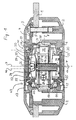
- Fig. 1 shows a longitudinal section through a Door opener switch according to the invention.
- the switch has a multi-part tubular housing, which in a Mounting surface 1 is installed. With the mounting surface 1 it can in particular, a glass door of a public Trade means of transport.
- the housing is made in particular a rear hollow cylindrical shell 2 and a front cover 3.
- the cover 3 in particular covers the jacket carrier 4, which has at least one opening, through which a screw 5 in an associated thread of the rear shell 2 is screwed. That way is the Door opener switch fixed in the mounting plate 1.
- a housing ring 6 is inserted, which in its interior analogous to the housing-jacket support. 4 is configured and with respect to the housing axis 7 as well the vertical plane of the switch 8 symmetrical Interior leaves.
- Symmetrical to this plane 8 are two printed circuit boards 9 and 10th arranged parallel to each other.
- diodes 11 are provided in particular, preferably in a diode ring the end faces 12 and 13 of the Door opener switch light and for a user the Improve visibility of the switch or give it the Signal the operating state of the switch. This is it Of course, necessary that the housing elements 4 and 6 from a translucent material are made.
- the circuit boards 9 and 10 have a hole located about the axis 14, wherein the axis 14 is at a small distance from the Example 1 millimeter parallel to the housing longitudinal axis 7 extends. In this opening through the circuit board 9 and 10th through a sleeve 15 is inserted, in which a Lever element 16 is mounted.
- This lever element 16 is in Direction of its axis of symmetry 14 slidably.
- the Lever element has a front on its front Stop collar 17, a stop for the movement of first lever element 16 in the rear switch area forms.
- the circuit boards 9 and 10 are in an annular Printed circuit board carrier 18 embedded, which is between the and is supported against the housing elements 4 and 6. They are lying each on a variety of small pyramids 38 and become when placing the housing elements 4 and 6 respectively this pressed on. This results in a in their axial position defined outwardly facing surface of the circuit boards. 9 and 10. These named compounds are subsequently ultrasonically welded to a one-piece, tight switching unit to obtain. In the sleeve, an opening is inserted through the connection cables 28 can be led out laterally.
- the switching function is via a front hood 20 and over a rear pressure hood 30 is triggered, both preferably have a larger diameter.
- the pressure hood 20 and 30 are with the elements 4 and 6 via a sealing elastic sealing bellows connected, the closer in the Fig. 4 is shown.
- the pressure hoods 20 and 30 are in particular along its axis of symmetry 7 in the direction of the center of the housing Door opener switch displaceable. In the in Fig. 1 shown rest position of the switch is doing the Pressure hood 20, which is connected to the print hood carrier 22, in a stop with the help of the collar 21. The same applies to the pressure hood 30, which has a corresponding stop 34 is secured against falling out of the element 6.
- the aforementioned lever member 16 has a laterally of the axis 14 relative to the axis 7 offset pivot bearing 23, which in particular has a ball socket into which a Projection 24 of a lever 25 is mounted. How through the parallel to the housing axis 7 shown further axis 46 to recognize is the pivot bearing 23 in a lateral Distance from the housing longitudinal axis 7 is arranged, the is greater than the distance between the axis of symmetry 14 of the Lever element 16 and the housing longitudinal axis 7. He is for example, 2.2 millimeters.
- the lever 25 has a transverse axis, in which a wheel 26 is mounted, which abuts against a leaf spring 27.
- the lever 25 has via a lever end 29, which in an example eight- to ten times greater distance from the housing longitudinal axis 7 opposite the further longitudinal axis 46 is arranged.
- the lever end 29 is in contact with a spring-loaded Actuating cam 31, the mechanical switching element 32nd assigned.
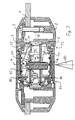
- FIG. 2 The function of the electric door opener switch at a Actuation from the front is now in FIG. 2 shown. Same features are in all figures with the the same reference numerals. Because of However, clarity is not all in all figures Called elements.
- the arrow 40 is the admission the front pressure hood 20 is symbolized with a force.
- the print hood carrier 22 in the direction of Housing longitudinal axis 7 is moved into the interior of the switch.
- the one with the reference numeral 21 dissolves mentioned stop.
- With the movement of the print-hood carrier 22 is also the leaf spring 27 of the print hood carrier 22nd moved against the wheel 26 is in the attack. By the lateral offset of the pivot bearing 23 rolls the wheel 26 on the leaf spring 27 and moves away from the housing longitudinal axis 7.
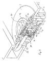
- FIG. 4 shows a built-in Door opener switch in a glass door, so that the mounting plate 1 for example, made of glass.
- the reference numeral 53 are denotes the electrical leads, which in a frame 54th the glass sheet 1 are guided to a control circuit.
- the Mechanical switching element 32 to recognize which over the Actuating cam 31 is switched.
- the lever 25 is around an elongated element, in which in a transverse extending slot the wheel 26 is mounted.
- Fig. 4 is particularly well the collar 34 of the rear hood support 33rd to recognize and the front and rear sealing bellows 55th
- the restoring force is essentially exclusively generated by the spring-actuated actuating cam 31, the after End of loading the front or rear pressure hood 20th or 30 by a force these pressure hoods 20 or 30 by a Returning the lever 25 returns to its normal position. This happens because the lever 25 on the one hand with his cam 24 the Lever 16 with its collar 17 in a stop with the PCB 9 presses and on the other hand, the wheel 26 in his Quiescent strives, the front hood 20 in a stop with the collar 21 leads.
- the rear jacket 2 forms the switch covering and aesthetically designed rear rosette, which holds the glass 1 between itself and the Element 4 holds, on this element 4, the front Rosette 3 is engaged.
- the door opener switch can also drawings the mounting plate 1 be designed symmetrically. in the However, in general, the illustrated embodiment, at the flat side with the pressure hood 20 to the outside is aligned, to a greater operational safety, since this damage is easier to resist.
Landscapes
- Switch Cases, Indication, And Locking (AREA)
- Push-Button Switches (AREA)
- Lock And Its Accessories (AREA)
- Electric Ovens (AREA)
Description
- Fig. 1
- einen Längsschnitt durch einen Türöffnerschalter gemäss der Erfindung,
- Fig. 2
- die Funktion des Türöffnerschalters nach Fig. 1 bei einer Betätigung von der Vorderseite aus,
- Fig. 3
- die Funktion des Türöffnerschalters nach Fig. 1 bei einer Betätigung von der Rückseite aus, und
- Fig. 4
- eine perspektivische Ansicht des in eine Glastür eingebauten Türöffnerschalters nach Fig. 1
Claims (8)
- Türöffnerschalter mit einem rohrförmigen Gehäuse (4, 6) und einer im Gehäuse (4, 6) axial beweglichen Taste (20) zur Betätigung eines mit dem Gehäuse verbundenen Schaltorgans (32), wobei die Taste (20) durch eine Rückstellkraft (31) in ihrer Ruhelage gehalten und gegen die Wirkung dieser Rückstellkraft (31) eindrückbar ist, mit einem im Verschiebeweg der Taste (20) quer orientierten und von der Taste (20) um ein Schwenklager (23) schwenkbaren Hebel (25), der mit einer vom Schwenklager beabstandeten Stelle (29) auf das Schaltorgan (31, 32) einwirkt, wobei die Taste (20) zwischen dem Schwenklager (23) und der erwähnten Stelle (29) den Hebel (25) berührt (26), dadurch gekennzeichnet, dass auf der Rückseite des Gehäuses (4, 6) eine weitere Taste (30) vorgesehen ist, die konzentrisch zu der ersten Taste (20) angeordnet ist, dass das Schwenklager (23) in einem Hebelelement (16) vorgesehen ist, welches in Richtung der Gehäuselängsachse (7) in Richtung der ersten Taste (20) verschieblich ist, dass die weitere Taste (30) das Hebelelement (16; 36) berührt und dass die weitere Taste (30) durch die Rückstellkraft (31) in ihrer Ruhelage gehalten und gegen die Wirkung dieser Rückstellkraft eindrückbar ist.
- Türöffnerschalter nach Anspruch 1, dadurch gekennzeichnet, dass der Berührpunkt des Hebels (25) mit der ersten Taste (20) und der Berührpunkt des Hebelelementes (16; 36) mit der weiteren Taste (30) in der Gehäuselängsachse (7) liegen, dem gegenüber (7) das Schwenklager (23) seitlich beabstandet (46) ist.
- Türöffnerschalter nach Anspruch 2, dadurch gekennzeichnet, dass die Tasten (20, 30) um die Berührpunkte kippbar sind.
- Türöffnerschalter nach einem der Ansprüche 1 bis 3, dadurch gekennzeichnet, dass das Schwenklager (23) ein Universalgelenk ist.
- Türöffnerschalter nach einem der Ansprüche 1 bis 4, dadurch gekennzeichnet, dass die Rückstellkraft im wesentlichen von der im Schaltorgan (32) vorhandenen und auf die Betätigungsnocke (29) wirkende Rückstellfeder aufgebracht wird.
- Türöffnerschalter nach Anspruch 5, dadurch gekennzeichnet, dass die Tasten (20, 30) eine mit einem Druckhaubenträger (22, 33) verbundene Druckhaube aufweisen, die im Gehäuse (4, 6) mit radialem Spiel geführt ist, und dass in der Ruhelage der Tasten (20, 30) die jeweiligen Druckhaubenträger (22, 33) mit bezüglich der Gehäuselängsachse (7) radial symmetrisch verteilten Anschlägen (21, 34) an gehäusefesten Anschlagflächen anliegen und an diesen durch die Rückstellkraft gehalten sind.
- Türöffnerschalter nach einem der Ansprüche 1 bis 6, dadurch gekennzeichnet, dass im Gehäuse (4, 6, 18) quer zum Verschiebeweg der Tasten (20, 30) ein das Schwenklager (23) aufweisende Hebelelement (16) sowie das Schaltorgan (31, 32) umfassende Leiterplattenpaar (9, 10) spielfrei befestigt ist.
- Türöffnerschalter nach Anspruch 7, dadurch gekennzeichnet, dass das die Druckhauben umgebende Gehäuse (4, 6) aus lichtdurchlässigem Material besteht, dass die Leiterplatten (9, 10) im Bereich der Gehäusewand mit zu der jeweiligen Gehäuseseite weisenden Leuchtdioden (11) bestückt sind und dass die Gehäusewand (4, 6) über Ausnehmungen zur Aufnahme der Leuchtdioden (11) versehen ist.
Applications Claiming Priority (1)
| Application Number | Priority Date | Filing Date | Title |
|---|---|---|---|
| PCT/CH2000/000008 WO2001050486A1 (de) | 2000-01-05 | 2000-01-05 | Türöffnerschalter |
Publications (2)
| Publication Number | Publication Date |
|---|---|
| EP1245033A1 EP1245033A1 (de) | 2002-10-02 |
| EP1245033B1 true EP1245033B1 (de) | 2003-05-21 |
Family
ID=4358027
Family Applications (1)
| Application Number | Title | Priority Date | Filing Date |
|---|---|---|---|
| EP00900016A Expired - Lifetime EP1245033B1 (de) | 2000-01-05 | 2000-01-05 | Türöffnerschalter |
Country Status (6)
| Country | Link |
|---|---|
| US (1) | US6713703B1 (de) |
| EP (1) | EP1245033B1 (de) |
| JP (1) | JP2003519886A (de) |
| AT (1) | ATE241209T1 (de) |
| DE (1) | DE50002312D1 (de) |
| WO (1) | WO2001050486A1 (de) |
Families Citing this family (5)
| Publication number | Priority date | Publication date | Assignee | Title |
|---|---|---|---|---|
| DE20208683U1 (de) * | 2002-06-05 | 2002-08-14 | Bernstein AG, 32457 Porta Westfalica | Handbetätigbares, elektrisches Bedienungsteil |
| DK2474987T3 (da) * | 2011-01-05 | 2013-08-19 | Eao Holding Ag | Indbygget kontakt |
| JP6983711B2 (ja) * | 2018-03-29 | 2021-12-17 | Nkkスイッチズ株式会社 | 押ボタンスイッチ |
| JP7032205B2 (ja) * | 2018-03-29 | 2022-03-08 | Nkkスイッチズ株式会社 | 押ボタンスイッチ |
| US12110720B2 (en) | 2021-01-26 | 2024-10-08 | Rev Ambulance Group Orlando, Inc. | Vehicle door including push button actuator |
Family Cites Families (5)
| Publication number | Priority date | Publication date | Assignee | Title |
|---|---|---|---|---|
| US1901385A (en) * | 1930-07-24 | 1933-03-14 | Warnell Patents Ltd | Electric iron |
| US2910564A (en) * | 1958-09-26 | 1959-10-27 | Robert C Mcbroom | Limit switch |
| US3274367A (en) * | 1964-07-06 | 1966-09-20 | William R Clark | Automobile light switch |
| EP0749136B1 (de) * | 1995-06-14 | 2003-04-09 | Eao Ag | Türöffnerschalter |
| US6345464B1 (en) * | 1999-01-13 | 2002-02-12 | Surefire, Llc | Firearms with target illuminators, electric switching devices and battery power sources |
-
2000
- 2000-01-05 AT AT00900016T patent/ATE241209T1/de active
- 2000-01-05 DE DE50002312T patent/DE50002312D1/de not_active Expired - Lifetime
- 2000-01-05 WO PCT/CH2000/000008 patent/WO2001050486A1/de not_active Ceased
- 2000-01-05 EP EP00900016A patent/EP1245033B1/de not_active Expired - Lifetime
- 2000-01-05 JP JP2001550769A patent/JP2003519886A/ja active Pending
- 2000-01-05 US US10/169,784 patent/US6713703B1/en not_active Expired - Lifetime
Also Published As
| Publication number | Publication date |
|---|---|
| US6713703B1 (en) | 2004-03-30 |
| EP1245033A1 (de) | 2002-10-02 |
| JP2003519886A (ja) | 2003-06-24 |
| ATE241209T1 (de) | 2003-06-15 |
| DE50002312D1 (de) | 2003-06-26 |
| WO2001050486A1 (de) | 2001-07-12 |
Similar Documents
| Publication | Publication Date | Title |
|---|---|---|
| EP1496529B1 (de) | Bedienungsgerät für die Handbetätigung von Hebezeugen | |
| EP1695868B1 (de) | Multifunktionstastschalter | |
| EP0749136B1 (de) | Türöffnerschalter | |
| EP0377116A2 (de) | Tastschalter | |
| DE102015117778A1 (de) | Kameraeinrichtung für ein Kraftfahrzeug | |
| DE2224555A1 (de) | Schaltwerk mit Sprungmechanik für Schalter und elektrische Signalgeber | |
| EP2206132B1 (de) | Betätiger | |
| DE69908076T2 (de) | Schalteranordnung | |
| DE102007054347B3 (de) | Manuell betätigbarer Schalter | |
| EP0592925B1 (de) | Handgefahrenmelder | |
| DE102013003574A1 (de) | Druck- und drehbetätigbares Bedienelement für ein Kraftfahrzeug | |
| EP0024620B1 (de) | Taste mit Leuchtanzeige für Tastaturen in Büro- und Fernschreibmaschinen | |
| EP1245033A1 (de) | Türöffnerschalter | |
| EP2478541B1 (de) | Betätiger mit signalanzeige | |
| DE3440442A1 (de) | Einbaudrucktaster fuer fahrzeugtueren | |
| DE3629650A1 (de) | Tastschalter | |
| DE19506896B4 (de) | Elektrischer Schalter | |
| DE3914403C2 (de) | ||
| DE1765167B2 (de) | Elektrischer druckknopfschalter | |
| DE102024111485B3 (de) | Fußschalter | |
| DE4415665A1 (de) | Bedienteil für ein elektrisches Gerät | |
| EP1480793B1 (de) | Allesschneider mit sicherheitsschalter | |
| DE102009040768B3 (de) | Betätiger mit Signalanzeige | |
| DE102021000442B4 (de) | Türgriff zur Türschlossbetätigung, insbesondere für ein Fahrzeug | |
| WO2011032775A1 (de) | Betätiger |
Legal Events
| Date | Code | Title | Description |
|---|---|---|---|
| PUAI | Public reference made under article 153(3) epc to a published international application that has entered the european phase |
Free format text: ORIGINAL CODE: 0009012 |
|
| 17P | Request for examination filed |
Effective date: 20020701 |
|
| AK | Designated contracting states |
Kind code of ref document: A1 Designated state(s): AT BE CH CY DE DK ES FI FR GB GR IE IT LI LU MC NL PT SE |
|
| GRAH | Despatch of communication of intention to grant a patent |
Free format text: ORIGINAL CODE: EPIDOS IGRA |
|
| GRAH | Despatch of communication of intention to grant a patent |
Free format text: ORIGINAL CODE: EPIDOS IGRA |
|
| GRAA | (expected) grant |
Free format text: ORIGINAL CODE: 0009210 |
|
| AK | Designated contracting states |
Designated state(s): AT BE CH CY DE DK ES FI FR GB GR IE IT LI LU MC NL PT SE |
|
| PG25 | Lapsed in a contracting state [announced via postgrant information from national office to epo] |
Ref country code: NL Free format text: LAPSE BECAUSE OF FAILURE TO SUBMIT A TRANSLATION OF THE DESCRIPTION OR TO PAY THE FEE WITHIN THE PRESCRIBED TIME-LIMIT Effective date: 20030521 Ref country code: FI Free format text: LAPSE BECAUSE OF FAILURE TO SUBMIT A TRANSLATION OF THE DESCRIPTION OR TO PAY THE FEE WITHIN THE PRESCRIBED TIME-LIMIT Effective date: 20030521 Ref country code: IE Free format text: LAPSE BECAUSE OF FAILURE TO SUBMIT A TRANSLATION OF THE DESCRIPTION OR TO PAY THE FEE WITHIN THE PRESCRIBED TIME-LIMIT Effective date: 20030521 Ref country code: CY Free format text: LAPSE BECAUSE OF FAILURE TO SUBMIT A TRANSLATION OF THE DESCRIPTION OR TO PAY THE FEE WITHIN THE PRESCRIBED TIME-LIMIT Effective date: 20030521 |
|
| REG | Reference to a national code |
Ref country code: GB Ref legal event code: FG4D Free format text: NOT ENGLISH |
|
| REG | Reference to a national code |
Ref country code: CH Ref legal event code: NV Representative=s name: ISLER & PEDRAZZINI AG Ref country code: CH Ref legal event code: EP |
|
| REG | Reference to a national code |
Ref country code: IE Ref legal event code: FG4D Free format text: GERMAN |
|
| REF | Corresponds to: |
Ref document number: 50002312 Country of ref document: DE Date of ref document: 20030626 Kind code of ref document: P |
|
| PG25 | Lapsed in a contracting state [announced via postgrant information from national office to epo] |
Ref country code: GR Free format text: LAPSE BECAUSE OF FAILURE TO SUBMIT A TRANSLATION OF THE DESCRIPTION OR TO PAY THE FEE WITHIN THE PRESCRIBED TIME-LIMIT Effective date: 20030821 Ref country code: PT Free format text: LAPSE BECAUSE OF FAILURE TO SUBMIT A TRANSLATION OF THE DESCRIPTION OR TO PAY THE FEE WITHIN THE PRESCRIBED TIME-LIMIT Effective date: 20030821 Ref country code: SE Free format text: LAPSE BECAUSE OF FAILURE TO SUBMIT A TRANSLATION OF THE DESCRIPTION OR TO PAY THE FEE WITHIN THE PRESCRIBED TIME-LIMIT Effective date: 20030821 Ref country code: DK Free format text: LAPSE BECAUSE OF FAILURE TO SUBMIT A TRANSLATION OF THE DESCRIPTION OR TO PAY THE FEE WITHIN THE PRESCRIBED TIME-LIMIT Effective date: 20030821 |
|
| PG25 | Lapsed in a contracting state [announced via postgrant information from national office to epo] |
Ref country code: ES Free format text: LAPSE BECAUSE OF FAILURE TO SUBMIT A TRANSLATION OF THE DESCRIPTION OR TO PAY THE FEE WITHIN THE PRESCRIBED TIME-LIMIT Effective date: 20030901 |
|
| NLV1 | Nl: lapsed or annulled due to failure to fulfill the requirements of art. 29p and 29m of the patents act | ||
| GBT | Gb: translation of ep patent filed (gb section 77(6)(a)/1977) |
Effective date: 20031021 |
|
| REG | Reference to a national code |
Ref country code: IE Ref legal event code: FD4D Ref document number: 1245033E Country of ref document: IE |
|
| PG25 | Lapsed in a contracting state [announced via postgrant information from national office to epo] |
Ref country code: LU Free format text: LAPSE BECAUSE OF NON-PAYMENT OF DUE FEES Effective date: 20040105 |
|
| PG25 | Lapsed in a contracting state [announced via postgrant information from national office to epo] |
Ref country code: BE Free format text: LAPSE BECAUSE OF NON-PAYMENT OF DUE FEES Effective date: 20040131 Ref country code: MC Free format text: LAPSE BECAUSE OF NON-PAYMENT OF DUE FEES Effective date: 20040131 |
|
| ET | Fr: translation filed | ||
| PLBE | No opposition filed within time limit |
Free format text: ORIGINAL CODE: 0009261 |
|
| STAA | Information on the status of an ep patent application or granted ep patent |
Free format text: STATUS: NO OPPOSITION FILED WITHIN TIME LIMIT |
|
| 26N | No opposition filed |
Effective date: 20040224 |
|
| BERE | Be: lapsed |
Owner name: *EAO A.G. Effective date: 20040131 |
|
| PG25 | Lapsed in a contracting state [announced via postgrant information from national office to epo] |
Ref country code: IT Free format text: LAPSE BECAUSE OF NON-PAYMENT OF DUE FEES Effective date: 20050105 |
|
| REG | Reference to a national code |
Ref country code: CH Ref legal event code: PCAR Free format text: ISLER & PEDRAZZINI AG;POSTFACH 1772;8027 ZUERICH (CH) |
|
| PGRI | Patent reinstated in contracting state [announced from national office to epo] |
Ref country code: IT Effective date: 20091201 |
|
| REG | Reference to a national code |
Ref country code: FR Ref legal event code: PLFP Year of fee payment: 16 |
|
| REG | Reference to a national code |
Ref country code: FR Ref legal event code: PLFP Year of fee payment: 17 |
|
| REG | Reference to a national code |
Ref country code: FR Ref legal event code: PLFP Year of fee payment: 18 |
|
| REG | Reference to a national code |
Ref country code: FR Ref legal event code: PLFP Year of fee payment: 19 |
|
| PGFP | Annual fee paid to national office [announced via postgrant information from national office to epo] |
Ref country code: CH Payment date: 20180111 Year of fee payment: 19 Ref country code: GB Payment date: 20180119 Year of fee payment: 19 Ref country code: DE Payment date: 20180122 Year of fee payment: 19 |
|
| PGFP | Annual fee paid to national office [announced via postgrant information from national office to epo] |
Ref country code: AT Payment date: 20180122 Year of fee payment: 19 Ref country code: IT Payment date: 20180129 Year of fee payment: 19 Ref country code: FR Payment date: 20180119 Year of fee payment: 19 |
|
| REG | Reference to a national code |
Ref country code: DE Ref legal event code: R119 Ref document number: 50002312 Country of ref document: DE |
|
| REG | Reference to a national code |
Ref country code: CH Ref legal event code: PL |
|
| REG | Reference to a national code |
Ref country code: AT Ref legal event code: MM01 Ref document number: 241209 Country of ref document: AT Kind code of ref document: T Effective date: 20190105 |
|
| GBPC | Gb: european patent ceased through non-payment of renewal fee |
Effective date: 20190105 |
|
| PG25 | Lapsed in a contracting state [announced via postgrant information from national office to epo] |
Ref country code: DE Free format text: LAPSE BECAUSE OF NON-PAYMENT OF DUE FEES Effective date: 20190801 Ref country code: FR Free format text: LAPSE BECAUSE OF NON-PAYMENT OF DUE FEES Effective date: 20190131 |
|
| PG25 | Lapsed in a contracting state [announced via postgrant information from national office to epo] |
Ref country code: GB Free format text: LAPSE BECAUSE OF NON-PAYMENT OF DUE FEES Effective date: 20190105 Ref country code: AT Free format text: LAPSE BECAUSE OF NON-PAYMENT OF DUE FEES Effective date: 20190105 Ref country code: CH Free format text: LAPSE BECAUSE OF NON-PAYMENT OF DUE FEES Effective date: 20190131 Ref country code: LI Free format text: LAPSE BECAUSE OF NON-PAYMENT OF DUE FEES Effective date: 20190131 |
|
| PG25 | Lapsed in a contracting state [announced via postgrant information from national office to epo] |
Ref country code: IT Free format text: LAPSE BECAUSE OF NON-PAYMENT OF DUE FEES Effective date: 20190105 |