EP1245004B1 - Verfahren, vorrichtung und rechnerprogramm zur überwachung eines gebiets - Google Patents
Verfahren, vorrichtung und rechnerprogramm zur überwachung eines gebiets Download PDFInfo
- Publication number
- EP1245004B1 EP1245004B1 EP00989154A EP00989154A EP1245004B1 EP 1245004 B1 EP1245004 B1 EP 1245004B1 EP 00989154 A EP00989154 A EP 00989154A EP 00989154 A EP00989154 A EP 00989154A EP 1245004 B1 EP1245004 B1 EP 1245004B1
- Authority
- EP
- European Patent Office
- Prior art keywords
- images
- image
- reference image
- recorded
- area
- Prior art date
- Legal status (The legal status is an assumption and is not a legal conclusion. Google has not performed a legal analysis and makes no representation as to the accuracy of the status listed.)
- Expired - Lifetime
Links
Images

Classifications
-
- G—PHYSICS
- G06—COMPUTING OR CALCULATING; COUNTING
- G06T—IMAGE DATA PROCESSING OR GENERATION, IN GENERAL
- G06T7/00—Image analysis
- G06T7/0002—Inspection of images, e.g. flaw detection
-
- G—PHYSICS
- G06—COMPUTING OR CALCULATING; COUNTING
- G06T—IMAGE DATA PROCESSING OR GENERATION, IN GENERAL
- G06T7/00—Image analysis
- G06T7/20—Analysis of motion
- G06T7/254—Analysis of motion involving subtraction of images
-
- G—PHYSICS
- G06—COMPUTING OR CALCULATING; COUNTING
- G06V—IMAGE OR VIDEO RECOGNITION OR UNDERSTANDING
- G06V20/00—Scenes; Scene-specific elements
- G06V20/50—Context or environment of the image
- G06V20/52—Surveillance or monitoring of activities, e.g. for recognising suspicious objects
-
- G—PHYSICS
- G08—SIGNALLING
- G08B—SIGNALLING SYSTEMS, e.g. PERSONAL CALLING SYSTEMS; ORDER TELEGRAPHS; ALARM SYSTEMS
- G08B13/00—Burglar, theft or intruder alarms
- G08B13/18—Actuation by interference with heat, light, or radiation of shorter wavelength; Actuation by intruding sources of heat, light, or radiation of shorter wavelength
- G08B13/189—Actuation by interference with heat, light, or radiation of shorter wavelength; Actuation by intruding sources of heat, light, or radiation of shorter wavelength using passive radiation detection systems
- G08B13/194—Actuation by interference with heat, light, or radiation of shorter wavelength; Actuation by intruding sources of heat, light, or radiation of shorter wavelength using passive radiation detection systems using image scanning and comparing systems
- G08B13/196—Actuation by interference with heat, light, or radiation of shorter wavelength; Actuation by intruding sources of heat, light, or radiation of shorter wavelength using passive radiation detection systems using image scanning and comparing systems using television cameras
- G08B13/19602—Image analysis to detect motion of the intruder, e.g. by frame subtraction
-
- G—PHYSICS
- G08—SIGNALLING
- G08B—SIGNALLING SYSTEMS, e.g. PERSONAL CALLING SYSTEMS; ORDER TELEGRAPHS; ALARM SYSTEMS
- G08B13/00—Burglar, theft or intruder alarms
- G08B13/18—Actuation by interference with heat, light, or radiation of shorter wavelength; Actuation by intruding sources of heat, light, or radiation of shorter wavelength
- G08B13/189—Actuation by interference with heat, light, or radiation of shorter wavelength; Actuation by intruding sources of heat, light, or radiation of shorter wavelength using passive radiation detection systems
- G08B13/194—Actuation by interference with heat, light, or radiation of shorter wavelength; Actuation by intruding sources of heat, light, or radiation of shorter wavelength using passive radiation detection systems using image scanning and comparing systems
- G08B13/196—Actuation by interference with heat, light, or radiation of shorter wavelength; Actuation by intruding sources of heat, light, or radiation of shorter wavelength using passive radiation detection systems using image scanning and comparing systems using television cameras
- G08B13/19602—Image analysis to detect motion of the intruder, e.g. by frame subtraction
- G08B13/19604—Image analysis to detect motion of the intruder, e.g. by frame subtraction involving reference image or background adaptation with time to compensate for changing conditions, e.g. reference image update on detection of light level change
-
- G—PHYSICS
- G08—SIGNALLING
- G08B—SIGNALLING SYSTEMS, e.g. PERSONAL CALLING SYSTEMS; ORDER TELEGRAPHS; ALARM SYSTEMS
- G08B13/00—Burglar, theft or intruder alarms
- G08B13/18—Actuation by interference with heat, light, or radiation of shorter wavelength; Actuation by intruding sources of heat, light, or radiation of shorter wavelength
- G08B13/189—Actuation by interference with heat, light, or radiation of shorter wavelength; Actuation by intruding sources of heat, light, or radiation of shorter wavelength using passive radiation detection systems
- G08B13/194—Actuation by interference with heat, light, or radiation of shorter wavelength; Actuation by intruding sources of heat, light, or radiation of shorter wavelength using passive radiation detection systems using image scanning and comparing systems
- G08B13/196—Actuation by interference with heat, light, or radiation of shorter wavelength; Actuation by intruding sources of heat, light, or radiation of shorter wavelength using passive radiation detection systems using image scanning and comparing systems using television cameras
- G08B13/19665—Details related to the storage of video surveillance data
- G08B13/19667—Details realated to data compression, encryption or encoding, e.g. resolution modes for reducing data volume to lower transmission bandwidth or memory requirements
-
- H—ELECTRICITY
- H04—ELECTRIC COMMUNICATION TECHNIQUE
- H04N—PICTORIAL COMMUNICATION, e.g. TELEVISION
- H04N7/00—Television systems
- H04N7/18—Closed-circuit television [CCTV] systems, i.e. systems in which the video signal is not broadcast
- H04N7/188—Capturing isolated or intermittent images triggered by the occurrence of a predetermined event, e.g. an object reaching a predetermined position
Definitions
- the present invention relates to a method for monitoring a monitored area, comprising the steps of recording an image of the monitored area and of comparing the recorded image with a reference image in order to determine if there is an alarm situation.
- the invention further relates to a monitoring unit and a computer program.
- the camera takes pictures of a monitored area.
- the monitored area is limited by the optics of the camera.
- the recorded images are analysed for an evaluation of their content to be made. If the camera monitors, for example, premises in which people are not permitted, an analysis is made of the recorded image and an evaluation made whether there is an extraneous object within the monitored area or not.
- the term scene is used.
- the scene changes for example, is something moves physically within the monitored area, for example if a person enters the monitored area.
- the scene does not change if the light in the monitored area changes. If a change of scene is detected, it can be determined that there is an alarm situation.
- the analysis of the recorded images can be carried out manually, by a person looking at a recorded image and making a visual evaluation about whether there is an intruder in the monitored area or not. If an intruder is discovered on a recorded image, the monitoring personnel who carries out the evaluation can, for example, telephone the police for further measures to be taken. This is an expensive form of monitoring, as it requires a person to go through the recorded images. Even if the person who carries out the evaluation of the recorded images can evaluate and monitor several monitored areas at the same time, it is time-consuming and very monotonous and stressful work, as an "event" that is not permitted must not be missed in the recorded images. In addition to an intruder entering a building, an event that is not permitted can be an incorrectly manufactured bottle in a production line.
- the analysis of the recorded images is therefore carried out to an increasing extent by means of digital image processing.
- a reference image which can be a background image that was recorded on a previous occasion when there was no intruder in the monitored area.
- the reference image can also be the immediately preceding recorded image.
- the reference image is derived by averaging a given number of previously acquired images.
- the reference image is formed by updating only the portions of the input image that contain background information. If there is a difference between the two compared images this can mean that there is an intruder in the monitored area.
- the difference can also be due to changes in the light in the monitored area, which for instance can arise when the sun goes behind a cloud, when it starts to get dark or when a light is switched on.
- One way of reducing the problem caused by changes in the light is to detect which changes concern changes in the light and which concern changes in the scene. This is solved by using different criteria for which changes in intensity are the result of changes in the light and which are the result of changes in the scene. This is a difficult problem to solve.
- the algorithms that are used are very complicated and take a long time to process.
- An object of the present invention is therefore to provide a method that avoids the above-mentioned problems.
- the changes in the light are now considered before the comparison is made. This is carried out by having previously stored images which can be combined and in this way can recreate the lighting conditions in the reference image.
- a new reference image can be created before each comparison with a recorded image. It is also possible to use the preceding reference image when the next image of the monitored area is recorded and is to be compared with a reference image. For example, a new reference image can be recreated every couple of minutes, or every fifth, tenth or hundredth time an image is recorded and is to be compared with a reference image.
- An advantage of the present invention is that an optimal reference image is obtained in a simple and quick way, which reference image takes the lighting conditions into account.
- Distributed intelligence means that an analysis of the recorded image is carried out in a monitoring unit at the monitored area to determine whether there is an alarm situation.
- the result of the comparison is also more reliable as the risk of a false detection is reduced when a reference image according to the invention is used.
- the monitoring can, for example, be carried out in premises where valuable documents are stored and in which people are not permitted, and aims at detecting whether a person is in the room or not.
- an image is recorded and the area which the image covers is called the monitored area.
- the recorded image is compared with a reference image in order to discover whether a person has entered the monitored area.
- the reference image is an image that represents the background of the monitored area at the time of recording the image.
- the background of the monitored area can be declared as the monitored area when no object that can cause an alarm is in the monitored area, that is to say when the monitored area is undisturbed.
- the reference image is created by combining images which are stored in a set of images, so that the reference image is adjusted to the prevalent lighting conditions in the recorded image.
- the image information in the reference image is adjusted to the image information in the recorded image.
- the image information comprises the light intensity in the pixels of the image.
- the images in the set of images do not need to correspond individually to an actual light level for the scene. What is important is that it is possible to create a reference image for as many different types of light level as possible from a limited number of images. It can be possible to update the set of images when the lighting conditions in the recorded image cannot be recreated in the reference image from the set of images.
- Another advantage is that the monitoring system is more robust and less sensitive to interference when the reference image is adjusted immediately to the prevalent lighting conditions and does not detect these separately afterwards.
- the reference image is created by linear combination of said at least two images.
- Linear combination means that a coefficient is calculated for each image in the set of images and the linear combination is created based on the calculated coefficients.
- the method further comprises in addition the steps of calculating a difference image as the difference between the reference image and the recorded image, determining at least one divergence area in the difference image in which at least certain pixels exceed a particular level, determining whether the divergence area represents a scene change and, if the divergence area represents a scene change, taking out the pixels that correspond to the divergence area in the recorded image, for the creation of the next reference image, or in the reference image, before comparison with the recorded image.
- the difference image can be derived as the difference in intensity between each pixel in the recorded image with each corresponding pixel in the reference image.
- the difference image it is possible to see whether, and if so where, there is a difference between the recorded image and the reference image.
- These differences can be apparent as a divergence area, which can be a number of pixels that exceed a predetermined threshold value and which are adjacent to each other.
- the number of divergence areas can be none, one or more.
- These divergence areas can be caused by scene changes, but they can also be caused, for example, by changes in the light.
- a divergence area there can be various criteria that have to be fulfilled.
- Such criteria can be that the area must be of a certain size, that is it must occupy at least a predetermined number of pixels and/or that the intensity difference in a pixel in the recorded image and the reference image must exceed a particular level.
- Other criteria can, for example, be the shape of the area, that is to say how the pixels that exceed the threshold value abut each other.
- the divergence area advantageously also comprises pixels that abut the pixels that fulfil one or more criteria for constituting a divergence area. By also removing these pixels, it is taken into account that the scene change may have moved in the monitored area before the recording of the next image. In this way, an even better reference image is obtained. How much the divergence area is enlarged can depend, for example, on how quickly it is expected that detected scene changes can move in the monitored area.
- the removed pixels are given a light level that is dependent upon the light level of the other pixels and an estimate of the lighting conditions in the area occupied by the scene change is obtained.
- An advantage of this method is that the reference image is created based on the prevalent lighting conditions without interference from scene changes.
- a further advantage of this method is that a better reference image is obtained and that it is thus easier to detect objects in the recorded image.
- Another advantage is that also less advanced algorithms are required, which in turn means that the calculation requires less processing capacity and less memory.
- the method comprises the steps of determining whether the divergence area represents a change in the light and of updating the set of images if the divergence area represents a change in the light.
- the divergence area represents a change in the light
- the light level in the recorded image could not be recreated from the set of images.
- New lighting conditions have been detected and the set of images is updated with these new lighting conditions.
- the base must be increased by a new image, but advantageously not with precisely the recorded image. Instead, what is important is that the new lighting conditions can be recreated with the set of images.
- the new set of images can be derived by using the recorded image plus the original set of images and performing a single value division (SVD).
- SSD single value division
- the base is orthogonal and the set of images is to be updated with a new image that corresponds to new lighting conditions, it is not sufficient simply to add the recorded image, as we wish to retain the orthogonal base. What is important is instead to be able to recreate the new lighting conditions with the new base.
- SVD it is possible to synthesise an image which is orthogonal to the others in the set of images.
- the method comprises the step of updating the set of images if the divergence area represents a scene change and if the same scene change is detected in a predetermined number of successively recorded images.
- Such a scene change is a persistent change and can, for example, be a flower-pot that has fallen on the floor. These persistent changes can be said to be noncritical changes of the scene.
- the number of images that is required in order to determine whether a persistent scene change has occurred is a matter of judgement.
- the number of images can also be measured in time as images can be recorded at predetermined intervals. It must not be the case that a burglar can be designated as a persistent scene change simply because he moves very slowly. For example, if a camera takes 10 images per second and a persistent scene change is defined as a change which lasts for one minute (or for three minutes) the number of images is 600.
- the updating can be carried out in such a way that a new set of images is created by discarding the old base and letting the most recently recorded image form a new set of images, which initially consists of only this one image.
- the scene change can also be incorporated gradually, whereas updating for a new light level should be carried out more rapidly.
- An advantage of this method is that a more correct reference image can be created.
- the step of determining whether the divergence area represents a scene change comprises calculating the variance of the divergence area, and if the variance exceeds a predetermined value it is determined that the divergence area represents a scene change.
- the variance of a divergence area in the difference image is calculated. If the variance is large, it is a scene change. If the variance is small, the divergence area can, for example, be judged to be due to a change in the lighting.
- An advantage of using the variance to determine which type of change has occurred is that it is a simple method.
- At least the outermost edge of pixels in the recorded image is omitted when creating the reference image.
- the stored images are stored in a set of images at different resolutions.
- An advantage of this is that it saves memory capacity, which is normally limited in a monitoring system. It is normally sufficient to store one or a few images at full resolution and the others at a considerably lower resolution.
- the step of creating the set of images further comprises recording images of the monitored area in different lighting conditions and storing one or more of these recorded images.
- a very large set of light levels can be stored in the set of images.
- One way of creating such a set of images is to take a sequence of images when starting up the system. This sequence of images can be taken over a predetermined period of time. During this time the light level varies as much as possible.
- An advantage of using such a set of images is that when there is a difference between the recorded image and the reference image, it can be determined straight away whether the difference is a scene change.
- a further advantage of this way of creating the set of images is that the derivation of a reference image from the set of images is quick and easy to carry out. It can also be possible to update this type of set of images if new lighting conditions arise.
- the step of updating the set of images is carried out at predetermined intervals.
- the whole set of images can advantageously be updated over time in order to prevent the set of images from becoming too large. That is to say that the set of images is updated so that it does not include lighting conditions that are not relevant.
- a time factor determines how long a time it is to take for the change to be incorporated in the base. For example, the updating can be carried out once an hour.
- said at least two images in the set of images are stored orthogonally.
- Storing images orthogonally means that the scalar product of each matrix that represents an image with itself is equal to one and that its scalar product with every other matrix that represents an image is equal to zero.
- An advantage of storing the set of images as an orthogonal base is that a large number of light variations can be captured in a limited number of images. For example, the continuum of light variations produced by a dimmer can be captured with only two base images.
- Another advantage of using an orthogonal base is that it is simpler and quicker to derive a reference image.
- the algorithms that are used can therefore be less complex and processing power is saved.
- a further advantage is that there are effective algorithms for updating the orthogonal base when new lighting conditions are detected.
- the set of images comprises an image in which all the pixels have the same intensity.
- An image in which all the pixels have the same intensity can be called a constant image.
- a constant image it is easy to capture variations where the whole scene is illuminated in the same way.
- intensity variations arise due, for example, to the exposure time being changed, as by using the constant image a monitoring unit can handle these settings automatically. This means that time-consuming manual settings are not required.
- a further advantage of using a constant image in comparison to, for example, calculating the intensity value of all the pixels with the same value, is that the calculation is quicker and easier.
- this relates to a monitoring unit for monitoring a monitored area, as defined in claim 13.
- this relates to a computer program.for image processing when monitoring a monitored area, which computer program is stored on a computer-readable memory medium which comprises instructions for causing the computer to record an image of the monitored area and to compare the recorded image with a reference image in order to determine whether there is an alarm situation, which causes the computer to create a reference image by combining at least two previously stored images from a set of images, so that the lighting conditions in the reference image are adjusted to the lighting conditions in the recorded image.
- the advantages of the computer program are apparent from the discussion above.
- the program is primarily intended to be installed in a monitoring unit which monitors a monitored area.
- Fig. 1 shows schematically a monitoring unit 1, which comprises a light-sensitive sensor 2 with an associated lens arrangement 3 which together are arranged to continuously record images of a monitored area.
- the monitored area can, for example, be premises in which people are not permitted.
- the monitoring unit 1 further comprises a central processing unit 4, which is arranged to process image information, a memory 5, in which previously recorded images can be stored, and a communication unit 6 for communication with an external unit. This communication can be carried out wirelessly.
- the external unit can, for example, be a central alarm centre to which information is sent if an alarm situation arises, which in the example mentioned above would be if a person were to enter the monitored premises.
- a monitoring unit 1 can, for example, be placed in a corner of a room and be directed so that it can cover and monitor a specific monitored area.
- the monitoring can be carried out as follows.
- the light-sensitive sensor records 100 an image of the monitored area.
- a reference image which is a representation of the background of the monitored area.
- the reference image represents the monitored area when there is no object in the image that should not be there.
- a reference image is created 110. This reference image is created by combining a number of previously recorded images (B 1 , B 2 , ..., B N ) that are stored in a set of images U. The images are combined in such a way that they reproduce as well as possible the lighting conditions in the recorded image.
- the reference image is then compared 120 with the recorded image in order to detect whether there has been any change in the recorded image.
- the set of images U can be created before the monitoring commences. For example, a sequence of images can be recorded for one minute. During this minute the light level is varied as much as possible.
- Each image is represented as a matrix with m x n elements, where the size of each element at position (i,j) corresponds to the recorded intensity of the point, usually called the pixel P. Normally, the intensity varies between 0 and 255, where 0 is black and 255 is white.
- Each of these N images is then converted to a vector, for example by so-called stacking in rows, or by all the pixels being placed in a vector of length mn in some other way.
- the first row is taken first, then the second is put after it and so on.
- M U ⁇ V T
- U and V are orthogonal matrices and ⁇ is a rectangular matrix consisting of zeros except at the locations (i,i) where the elements are called singular values.
- the columns in U describe the variation in the images B i and the corresponding singular value describes how large a weighting the column has in the description of all the lighting conditions.
- the singular values are arranged in order of size, with the largest first, which means that the first column in V describes the images best, then the second describes the variations from the first best, and so on. In order to determine how many images are to be included in the set of images, either the number can be fixed or a threshold can be put upon the singular values.
- the set of images is then obtained by creating matrices of the columns in U in the same way as the columns were created out of the matrices. In this way, the set of images is obtained, U 1 , ..., U b .
- the orthogonal set obtained is not necessarily a representation of images that can be obtained from reality, but are synthetic images using which it is possible to recreate an original set of images.
- the set of images is then updated gradually when the light-sensitive sensor 2 records new images which comprise light levels that are not represented in the set of images.
- Images in the set of images can be stored with limited resolution. Normally it is sufficient to store one or a few images at full resolution, that is to say that each pixel is stored, and the other images at a considerably lower resolution, for example every second row and every second column are stored. This saves memory capacity.
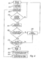
- An image of a monitored area is recorded 200.
- the recorded image is called B.
- Other norms or more general functions can also be used.
- a difference image is calculated 220 as the absolute amount of the difference between the reference image and the recorded image. If there are pixels that exceed 230 a certain level and these pixels constitute a coherent area of a minimum size, a divergence area is determined 240. The divergence area consists of these pixels and pixels that abut these pixels. There can be several divergence areas in one and the same difference image. Each divergence area is investigated.
- the variance of the difference image is calculated to determine in this way whether the divergence area represents a scene change or a lighting change 250. If the variance is large, the divergence area is judged to represent a scene change and if the variance is small, the divergence area is judged to represent a lighting change.
- NVD normalised vector distance
- a further technique comprises using quotients between intensities for adjacent pixels, which is described in US 5 956 424 .
- the scene change is judged to be persistent. For example, it can be a flower-pot that has fallen on the floor. Persistent scene changes are judged not to be critical.
- This persistent scene change is incorporated into the set of images by updating 260 the set of images. The updating can be such that a set of images is built up from scratch by discarding the old set of images, and using the recorded image to create a new set of images.
- the persistent scene change can also be incorporated gradually by, for example, storing the deviations separately in a separate set of images for only that part of the image. This can gradually be transferred to the set of images when all the lighting variations for the new object have been seen.
- a new image of the monitored area is recorded 280.
- the pixels taken up by the divergence area in the recorded image are removed 290 and the reference image is created 295 from the other pixels.
- the outermost rows and columns of the pixels can advantageously be removed when calculating the reference image, as a possible intruder first appears at the edge of the image and could thus possibly affect the reference image before detection has occurred.
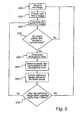
- Fig. 5 shows a flow chart for a further embodiment according to the invention.
- An image of a monitored area is recorded 300.
- a reference image is created 310 in a way as mentioned above.
- a difference image is calculated 320 as the absolute amount of the difference between the reference image and the recorded image. If there are pixels that exceed 330 a certain level and these pixels constitute a coherent area of a minimum size, a divergence area is determined 340.
- a new reference image is created in which the pixels taken up by the divergence area in the recorded image are removed 350 and the reference image is created 360 from the other pixels.
- the reference image is improved and refined by being repeated, for example, six times. If the reference image is not repeated 370 more than five times, a new difference image is calculated 320 and the process continues from there. When the image is repeated 370 more than five times, a new image of the monitored area is recorded 300 and a new reference image is created.
Landscapes
- Engineering & Computer Science (AREA)
- Physics & Mathematics (AREA)
- General Physics & Mathematics (AREA)
- Computer Vision & Pattern Recognition (AREA)
- Multimedia (AREA)
- Theoretical Computer Science (AREA)
- Signal Processing (AREA)
- Quality & Reliability (AREA)
- Closed-Circuit Television Systems (AREA)
- Image Analysis (AREA)
- Image Processing (AREA)
- Burglar Alarm Systems (AREA)
- Hardware Redundancy (AREA)
- Alarm Systems (AREA)
Claims (15)
- Verfahren zum Überwachen eines Überwachungsbereichs, umfassend die Schritte des Aufzeichnens eines Bildes des Überwachungsbereichs und des Vergleichens des aufgezeichneten Bildes mit einem Referenzbild, um festzustellen, ob eine Alarmsituation besteht, wobei der Schritt des Erzeugens des Referenzbildes den Schritt des Kombinierens von wenigstens zwei zuvor gespeicherten Bildern einer Bildergruppe enthält, so dass die Lichtverhältnisse in dem Referenzbild an die Lichtverhältnisse in dem aufgezeichneten Bild angepasst werden, und gekennzeichnet durch das Verwenden eines Algorithmus, der das Referenzbild auf Basis der Bildergruppe an das aufgezeichnete Bild anpasst und darauf abzielt, die Linearkombination von Bildern in der Bildergruppe zu finden, die so gut wie möglich dem Helligkeitswert in dem aufgezeichneten Bild entspricht.
- Verfahren nach Anspruch 1, wobei das Referenzbild durch Linearkombination von wenigstens zwei zuvor gespeicherten Bildern erzeugt wird.
- Verfahren nach einem der vorhergehenden Ansprüche, das des Weiteren die folgenden Schritte umfasst:Berechnen eines Differenzbildes als die Differenz zwischen dem Referenzbild und dem aufgezeichneten Bild,Bestimmen wenigstens eines Divergenzbereichs in dem Differenzbild, in dem wenigstens bestimmte Pixel einen speziellen Pegel übersteigen,Bestimmen, ob der Divergenzbereich einen Szenenwechsel darstellt, undfalls der Divergenzbereich einen Szenenwechsel darstellt,Entfernen der Pixel, die dem Divergenzbereich in dem aufgezeichneten Bild entsprechen, um das nächste Referenzbild zu erzeugen.
- Verfahren nach Anspruch 3, das des Weiteren die Schritte des Bestimmens, ob der Divergenzbereich einen Lichtwechsel darstellt, und falls der Divergenzbereich einen Lichtwechsel darstellt, des Aktualisierens der Bildergruppe umfasst.
- Verfahren nach Anspruch 3, das des Weiteren den Schritt des Aktualisierens der Bildergruppe umfasst, falls der Divergenzbereich einen Szenenwechsel darstellt und falls derselbe Szenenwechsel in einer vorgegebenen Anzahl von konsekutiv aufgezeichneten Bildern detektiert wird.
- Verfahren nach einem der Ansprüche 3, 4 oder 5, wobei der Schritt des Bestimmens, ob der Divergenzbereich einen Szenenwechsel darstellt, den Schritt des Berechnens der Varianz des Divergenzbereichs umfasst und wobei, falls die Varianz einen vorgegebenen Wert übersteigt, der Divergenzbereich als einen Szenenwechsel darstellend bewertet wird.
- Verfahren nach einem der vorhergehenden Ansprüche, wobei beim Erzeugen des Referenzbildes wenigstens die äußerste Kante von PixeIn in dem aufgezeichneten Bild ausgeschlossen wird.
- Verfahren nach einem der vorhergehenden Ansprüche, wobei die gespeicherten Bilder in der Bildergruppe mit verschiedenen Auflösungen gespeichert werden.
- Verfahren nach einem der vorhergehenden Ansprüche, das des Weiteren den Schritt des Erzeugens der Bildergruppe durch Aufzeichnungsbilder des Überwachungsbereichs bei verschiedenen Lichtverhältnissen und des Speicherns eines oder mehrerer dieser aufgezeichneten Bilder umfasst.
- Verfahren nach einem der Ansprüche 4 oder 5, wobei der Schritt des Aktualisierens der Bildergruppe in vorgegebenen Intervallen ausgeführt wird.
- Verfahren nach einem der vorhergehenden Ansprüche, wobei wenigstens zwei Bilder in der Bildergruppe orthogonal gespeichert werden, so dass das Skalarprodukt jeder Matrix, die ein Bild darstellt, mit sich selbst gleich eins ist und dass ihr Skalarprodukt mit jeder anderen Matrix, die ein Bild darstellt, gleich null ist.
- Verfahren nach einem der vorhergehenden Ansprüche, wobei die Bildergruppe ein Bild umfasst, in dem alle Pixel dieselbe Intensität haben.
- Überwachungseinheit zum Überwachen eines Überwachungsbereichs, umfassend einen lichtempfindlichen Sensor, der eingerichtet ist, um ein Bild des Überwachungsbereichs aufzuzeichnen, und eine CPU, die eingerichtet ist, um das aufgezeichnete Bild mit einem Referenzbild zu vergleichen, um festzustellen, ob eine Alarmsituation besteht, wobei die CPU des Weiteren eingerichtet ist, um durch Kombinieren von wenigstens zwei zuvor gespeicherten Bildern aus einer Bildergruppe ein Referenzbild zu erzeugen, so dass die Lichtverhältnisse in dem Referenzbild an die Lichtverhältnisse in dem aufgezeichneten Bild angepasst werden, und dadurch gekennzeichnet, dass die CPU einen Algorithmus verwendet, der das Referenzbild auf Basis der Bildergruppe an das aufgezeichnete Bild anpasst und darauf abzielt, die Linearkombination von Bildern in der Bildergruppe zu finden, die so gut wie möglich dem Helligkeitswert in dem aufgezeichneten Bild entspricht.
- Computerprogramm für Bildverarbeitung zum Überwachen eines Überwachungsbereichs, wobei das Computerprogramm auf einem computerlesbaren Speichermedium gespeichert ist, das Befehle umfasst, um den Computer zu veranlassen, die Schritte des Verfahrens nach Anspruch 1 auszuführen.
- Computerprogramm für Bildverarbeitung zum Überwachen eines Überwachungsbereichs, wobei das Computerprogramm auf einem computerlesbaren Speichermedium gespeichert ist, das Befehle zum Ausführen eines oder mehrerer der Verfahrensschritte nach Anspruch 1 bis 12 umfasst.
Applications Claiming Priority (5)
| Application Number | Priority Date | Filing Date | Title |
|---|---|---|---|
| SE9904741A SE517900C2 (sv) | 1999-12-23 | 1999-12-23 | Sätt,övervakningssystem och övervakningsenhet för övervakning av en övervakningsplats |
| SE9904742 | 1999-12-23 | ||
| SE9904742A SE519700C2 (sv) | 1999-12-23 | 1999-12-23 | Bilddatabehandling |
| SE9904741 | 1999-12-23 | ||
| PCT/SE2000/002664 WO2001048696A1 (en) | 1999-12-23 | 2000-12-22 | Method, device and computer program for monitoring an area |
Publications (2)
| Publication Number | Publication Date |
|---|---|
| EP1245004A1 EP1245004A1 (de) | 2002-10-02 |
| EP1245004B1 true EP1245004B1 (de) | 2008-07-23 |
Family
ID=26663700
Family Applications (1)
| Application Number | Title | Priority Date | Filing Date |
|---|---|---|---|
| EP00989154A Expired - Lifetime EP1245004B1 (de) | 1999-12-23 | 2000-12-22 | Verfahren, vorrichtung und rechnerprogramm zur überwachung eines gebiets |
Country Status (6)
| Country | Link |
|---|---|
| EP (1) | EP1245004B1 (de) |
| JP (1) | JP4753340B2 (de) |
| AT (1) | ATE402457T1 (de) |
| AU (1) | AU2569701A (de) |
| DE (1) | DE60039630D1 (de) |
| WO (1) | WO2001048696A1 (de) |
Families Citing this family (8)
| Publication number | Priority date | Publication date | Assignee | Title |
|---|---|---|---|---|
| US7131125B2 (en) | 2000-12-22 | 2006-10-31 | Nortel Networks Limited | Method and system for sharing a computer resource between instruction threads of a multi-threaded process |
| SE519279C2 (sv) * | 2001-06-21 | 2003-02-11 | Wespot Ab | Anpassade filter för detektering av scenförändring |
| US7203337B2 (en) | 2001-06-21 | 2007-04-10 | Wespot Ab | Adjusted filters |
| FI112018B (fi) * | 2001-12-18 | 2003-10-15 | Hantro Products Oy | Menetelmä ja laite liikkeen tunnistamiseksi |
| SE0203483D0 (sv) | 2002-11-21 | 2002-11-21 | Wespot Ab | Method and device for fall detection |
| ATE521054T1 (de) | 2006-12-20 | 2011-09-15 | Axis Ab | Verfahen und einrichtung zur erkennung von sabotage an einer überwachungskamera |
| CN105847767B (zh) * | 2016-05-31 | 2018-07-06 | 浪潮通用软件有限公司 | 一种告警方法、装置及系统 |
| DE102020215227B4 (de) * | 2020-12-02 | 2023-11-09 | TRUMPF Werkzeugmaschinen SE + Co. KG | Vorrichtung und Verfahren zum Erstellen einer Referenzaufnahme des unbeladenen Zustands eines Werkstückträgers |
Family Cites Families (11)
| Publication number | Priority date | Publication date | Assignee | Title |
|---|---|---|---|---|
| JPH04111079A (ja) * | 1990-08-30 | 1992-04-13 | Matsushita Electric Ind Co Ltd | 移動体識別装置 |
| JPH06223190A (ja) * | 1993-01-22 | 1994-08-12 | Toshiba Corp | 動物体検出装置 |
| JPH06333050A (ja) * | 1993-05-19 | 1994-12-02 | Oki Electric Ind Co Ltd | 監視画像の変化検出方法 |
| DE4332753C2 (de) * | 1993-09-25 | 1997-01-30 | Bosch Gmbh Robert | Verfahren zur Erkennung bewegter Objekte |
| JP3123587B2 (ja) * | 1994-03-09 | 2001-01-15 | 日本電信電話株式会社 | 背景差分による動物体領域抽出方法 |
| MY132441A (en) * | 1995-01-17 | 2007-10-31 | Sarnoff Corp | Method and apparatus for detecting object movement within an image sequence |
| JPH0950525A (ja) * | 1995-08-08 | 1997-02-18 | Canon Inc | 画像処理装置 |
| WO1997016921A1 (en) * | 1995-10-31 | 1997-05-09 | Sarnoff Corporation | Method and apparatus for generating a reference image from an image sequence |
| JPH09319978A (ja) * | 1996-05-31 | 1997-12-12 | Hitachi Ltd | 侵入物体監視装置 |
| JP4022984B2 (ja) * | 1998-04-28 | 2007-12-19 | ソニー株式会社 | 撮像装置及び撮像方法 |
| JP2000090277A (ja) * | 1998-09-10 | 2000-03-31 | Hitachi Denshi Ltd | 基準背景画像更新方法及び侵入物体検出方法並びに侵入物体検出装置 |
-
2000
- 2000-12-22 AT AT00989154T patent/ATE402457T1/de not_active IP Right Cessation
- 2000-12-22 DE DE60039630T patent/DE60039630D1/de not_active Expired - Lifetime
- 2000-12-22 AU AU25697/01A patent/AU2569701A/en not_active Abandoned
- 2000-12-22 WO PCT/SE2000/002664 patent/WO2001048696A1/en not_active Ceased
- 2000-12-22 EP EP00989154A patent/EP1245004B1/de not_active Expired - Lifetime
- 2000-12-22 JP JP2001548344A patent/JP4753340B2/ja not_active Expired - Fee Related
Also Published As
| Publication number | Publication date |
|---|---|
| EP1245004A1 (de) | 2002-10-02 |
| ATE402457T1 (de) | 2008-08-15 |
| JP2003521767A (ja) | 2003-07-15 |
| WO2001048696A1 (en) | 2001-07-05 |
| DE60039630D1 (de) | 2008-09-04 |
| JP4753340B2 (ja) | 2011-08-24 |
| AU2569701A (en) | 2001-07-09 |
Similar Documents
| Publication | Publication Date | Title |
|---|---|---|
| US6819353B2 (en) | Multiple backgrounds | |
| US20190244504A1 (en) | Fire monitoring system | |
| US20070273765A1 (en) | Method for Detecting Desired Objects in a Highly Dynamic Environment by a Monitoring System | |
| JP2000513848A (ja) | 大域変化に感応しないビデオ動き検出器 | |
| JP4999794B2 (ja) | 静止領域検出方法とその装置、プログラム及び記録媒体 | |
| CN115797346A (zh) | 极耳状态检测方法、装置、计算机设备和存储介质 | |
| EP1245004B1 (de) | Verfahren, vorrichtung und rechnerprogramm zur überwachung eines gebiets | |
| WO1998028706B1 (en) | Low false alarm rate video security system using object classification | |
| US7203337B2 (en) | Adjusted filters | |
| JP3486229B2 (ja) | 画像変化検出装置 | |
| JP2020071698A (ja) | 火災検知装置、火災検知方法及び火災監視システム | |
| JP6616906B1 (ja) | 欠陥のある撮影データの検知装置及び検知システム | |
| CN113408479A (zh) | 火焰检测方法、装置、计算机设备和存储介质 | |
| EP2447912B1 (de) | Verfahren und Vorrichtung zur Erfassung einer Veränderung der Beleuchtung für Sichtsysteme | |
| Kumar et al. | Computer vision-based early fire detection using machine learning | |
| JP2009545223A (ja) | イベント検出方法及び上記方法を用いたビデオ監視システム | |
| KR101581162B1 (ko) | 실시간 영상 기반의 화염, 연기 및 물체 움직임 자동 감지 방법, 장치 및 시스템 | |
| EP1364526A1 (de) | Szenenänderungsdetektion | |
| AU2002232008A1 (en) | Method of detecting a significant change of scene | |
| CN117635937A (zh) | 一种判断巡逻机器人摄像头遮挡告警的方法、系统和介质 | |
| KR102864354B1 (ko) | 열화상 이미지에서 반사를 식별하는 방법 및 시스템 | |
| JP3490196B2 (ja) | 画像処理装置及びその方法 | |
| JP4785087B2 (ja) | 録画判定装置および方法 | |
| CN119131534A (zh) | 翻拍图像识别方法、装置、电子设备及存储介质 | |
| CN117238117A (zh) | 基于巡检机器人的消防手动报警器异常检测方法与系统 |
Legal Events
| Date | Code | Title | Description |
|---|---|---|---|
| PUAI | Public reference made under article 153(3) epc to a published international application that has entered the european phase |
Free format text: ORIGINAL CODE: 0009012 |
|
| 17P | Request for examination filed |
Effective date: 20020723 |
|
| AK | Designated contracting states |
Kind code of ref document: A1 Designated state(s): AT BE CH CY DE DK ES FI FR GB GR IE IT LI LU MC NL PT SE TR |
|
| AX | Request for extension of the european patent |
Free format text: AL PAYMENT 20020723;LT PAYMENT 20020723;LV PAYMENT 20020723;MK PAYMENT 20020723;RO PAYMENT 20020723;SI PAYMENT 20020723 |
|
| D17P | Request for examination filed (deleted) | ||
| R17P | Request for examination filed (corrected) |
Effective date: 20020723 |
|
| RAP1 | Party data changed (applicant data changed or rights of an application transferred) |
Owner name: SECUMANAGEMENT B.V. |
|
| 17Q | First examination report despatched |
Effective date: 20061215 |
|
| GRAP | Despatch of communication of intention to grant a patent |
Free format text: ORIGINAL CODE: EPIDOSNIGR1 |
|
| GRAS | Grant fee paid |
Free format text: ORIGINAL CODE: EPIDOSNIGR3 |
|
| GRAA | (expected) grant |
Free format text: ORIGINAL CODE: 0009210 |
|
| AK | Designated contracting states |
Kind code of ref document: B1 Designated state(s): AT BE CH CY DE DK ES FI FR GB GR IE IT LI LU MC NL PT SE TR |
|
| AX | Request for extension of the european patent |
Extension state: AL LT LV MK RO SI |
|
| REG | Reference to a national code |
Ref country code: GB Ref legal event code: FG4D |
|
| REG | Reference to a national code |
Ref country code: CH Ref legal event code: EP |
|
| REG | Reference to a national code |
Ref country code: IE Ref legal event code: FG4D |
|
| REF | Corresponds to: |
Ref document number: 60039630 Country of ref document: DE Date of ref document: 20080904 Kind code of ref document: P |
|
| REG | Reference to a national code |
Ref country code: CH Ref legal event code: NV Representative=s name: OFFICE ERNEST T. FREYLINGER S.A. |
|
| NLV1 | Nl: lapsed or annulled due to failure to fulfill the requirements of art. 29p and 29m of the patents act | ||
| PG25 | Lapsed in a contracting state [announced via postgrant information from national office to epo] |
Ref country code: PT Free format text: LAPSE BECAUSE OF FAILURE TO SUBMIT A TRANSLATION OF THE DESCRIPTION OR TO PAY THE FEE WITHIN THE PRESCRIBED TIME-LIMIT Effective date: 20081223 Ref country code: ES Free format text: LAPSE BECAUSE OF FAILURE TO SUBMIT A TRANSLATION OF THE DESCRIPTION OR TO PAY THE FEE WITHIN THE PRESCRIBED TIME-LIMIT Effective date: 20081103 Ref country code: NL Free format text: LAPSE BECAUSE OF FAILURE TO SUBMIT A TRANSLATION OF THE DESCRIPTION OR TO PAY THE FEE WITHIN THE PRESCRIBED TIME-LIMIT Effective date: 20080723 |
|
| PG25 | Lapsed in a contracting state [announced via postgrant information from national office to epo] |
Ref country code: AT Free format text: LAPSE BECAUSE OF FAILURE TO SUBMIT A TRANSLATION OF THE DESCRIPTION OR TO PAY THE FEE WITHIN THE PRESCRIBED TIME-LIMIT Effective date: 20080723 Ref country code: FI Free format text: LAPSE BECAUSE OF FAILURE TO SUBMIT A TRANSLATION OF THE DESCRIPTION OR TO PAY THE FEE WITHIN THE PRESCRIBED TIME-LIMIT Effective date: 20080723 |
|
| PG25 | Lapsed in a contracting state [announced via postgrant information from national office to epo] |
Ref country code: BE Free format text: LAPSE BECAUSE OF FAILURE TO SUBMIT A TRANSLATION OF THE DESCRIPTION OR TO PAY THE FEE WITHIN THE PRESCRIBED TIME-LIMIT Effective date: 20080723 |
|
| PG25 | Lapsed in a contracting state [announced via postgrant information from national office to epo] |
Ref country code: DK Free format text: LAPSE BECAUSE OF FAILURE TO SUBMIT A TRANSLATION OF THE DESCRIPTION OR TO PAY THE FEE WITHIN THE PRESCRIBED TIME-LIMIT Effective date: 20080723 |
|
| PLBE | No opposition filed within time limit |
Free format text: ORIGINAL CODE: 0009261 |
|
| STAA | Information on the status of an ep patent application or granted ep patent |
Free format text: STATUS: NO OPPOSITION FILED WITHIN TIME LIMIT |
|
| 26N | No opposition filed |
Effective date: 20090424 |
|
| PG25 | Lapsed in a contracting state [announced via postgrant information from national office to epo] |
Ref country code: MC Free format text: LAPSE BECAUSE OF NON-PAYMENT OF DUE FEES Effective date: 20081231 |
|
| PG25 | Lapsed in a contracting state [announced via postgrant information from national office to epo] |
Ref country code: IT Free format text: LAPSE BECAUSE OF FAILURE TO SUBMIT A TRANSLATION OF THE DESCRIPTION OR TO PAY THE FEE WITHIN THE PRESCRIBED TIME-LIMIT Effective date: 20080723 |
|
| PG25 | Lapsed in a contracting state [announced via postgrant information from national office to epo] |
Ref country code: IE Free format text: LAPSE BECAUSE OF NON-PAYMENT OF DUE FEES Effective date: 20081222 |
|
| PG25 | Lapsed in a contracting state [announced via postgrant information from national office to epo] |
Ref country code: SE Free format text: LAPSE BECAUSE OF FAILURE TO SUBMIT A TRANSLATION OF THE DESCRIPTION OR TO PAY THE FEE WITHIN THE PRESCRIBED TIME-LIMIT Effective date: 20081023 |
|
| PG25 | Lapsed in a contracting state [announced via postgrant information from national office to epo] |
Ref country code: CY Free format text: LAPSE BECAUSE OF FAILURE TO SUBMIT A TRANSLATION OF THE DESCRIPTION OR TO PAY THE FEE WITHIN THE PRESCRIBED TIME-LIMIT Effective date: 20080723 Ref country code: LU Free format text: LAPSE BECAUSE OF NON-PAYMENT OF DUE FEES Effective date: 20081222 |
|
| PG25 | Lapsed in a contracting state [announced via postgrant information from national office to epo] |
Ref country code: TR Free format text: LAPSE BECAUSE OF FAILURE TO SUBMIT A TRANSLATION OF THE DESCRIPTION OR TO PAY THE FEE WITHIN THE PRESCRIBED TIME-LIMIT Effective date: 20080723 |
|
| PG25 | Lapsed in a contracting state [announced via postgrant information from national office to epo] |
Ref country code: GR Free format text: LAPSE BECAUSE OF FAILURE TO SUBMIT A TRANSLATION OF THE DESCRIPTION OR TO PAY THE FEE WITHIN THE PRESCRIBED TIME-LIMIT Effective date: 20081024 |
|
| PGFP | Annual fee paid to national office [announced via postgrant information from national office to epo] |
Ref country code: CH Payment date: 20141204 Year of fee payment: 15 Ref country code: GB Payment date: 20141205 Year of fee payment: 15 |
|
| PGFP | Annual fee paid to national office [announced via postgrant information from national office to epo] |
Ref country code: DE Payment date: 20141203 Year of fee payment: 15 |
|
| PGFP | Annual fee paid to national office [announced via postgrant information from national office to epo] |
Ref country code: FR Payment date: 20141212 Year of fee payment: 15 |
|
| REG | Reference to a national code |
Ref country code: DE Ref legal event code: R119 Ref document number: 60039630 Country of ref document: DE |
|
| REG | Reference to a national code |
Ref country code: CH Ref legal event code: PL |
|
| GBPC | Gb: european patent ceased through non-payment of renewal fee |
Effective date: 20151222 |
|
| REG | Reference to a national code |
Ref country code: FR Ref legal event code: ST Effective date: 20160831 |
|
| PG25 | Lapsed in a contracting state [announced via postgrant information from national office to epo] |
Ref country code: CH Free format text: LAPSE BECAUSE OF NON-PAYMENT OF DUE FEES Effective date: 20151231 Ref country code: DE Free format text: LAPSE BECAUSE OF NON-PAYMENT OF DUE FEES Effective date: 20160701 Ref country code: LI Free format text: LAPSE BECAUSE OF NON-PAYMENT OF DUE FEES Effective date: 20151231 Ref country code: GB Free format text: LAPSE BECAUSE OF NON-PAYMENT OF DUE FEES Effective date: 20151222 |
|
| PG25 | Lapsed in a contracting state [announced via postgrant information from national office to epo] |
Ref country code: FR Free format text: LAPSE BECAUSE OF NON-PAYMENT OF DUE FEES Effective date: 20151231 |