EP1244591B1 - Closure cap - Google Patents
Closure cap Download PDFInfo
- Publication number
- EP1244591B1 EP1244591B1 EP20000972992 EP00972992A EP1244591B1 EP 1244591 B1 EP1244591 B1 EP 1244591B1 EP 20000972992 EP20000972992 EP 20000972992 EP 00972992 A EP00972992 A EP 00972992A EP 1244591 B1 EP1244591 B1 EP 1244591B1
- Authority
- EP
- European Patent Office
- Prior art keywords
- reinforcing ribs
- closure cap
- cap
- head plate
- thread
- Prior art date
- Legal status (The legal status is an assumption and is not a legal conclusion. Google has not performed a legal analysis and makes no representation as to the accuracy of the status listed.)
- Expired - Lifetime
Links
Images


Classifications
-
- B—PERFORMING OPERATIONS; TRANSPORTING
- B65—CONVEYING; PACKING; STORING; HANDLING THIN OR FILAMENTARY MATERIAL
- B65D—CONTAINERS FOR STORAGE OR TRANSPORT OF ARTICLES OR MATERIALS, e.g. BAGS, BARRELS, BOTTLES, BOXES, CANS, CARTONS, CRATES, DRUMS, JARS, TANKS, HOPPERS, FORWARDING CONTAINERS; ACCESSORIES, CLOSURES, OR FITTINGS THEREFOR; PACKAGING ELEMENTS; PACKAGES
- B65D41/00—Caps, e.g. crown caps or crown seals, i.e. members having parts arranged for engagement with the external periphery of a neck or wall defining a pouring opening or discharge aperture; Protective cap-like covers for closure members, e.g. decorative covers of metal foil or paper
- B65D41/02—Caps or cap-like covers without lines of weakness, tearing strips, tags, or like opening or removal devices
- B65D41/04—Threaded or like caps or cap-like covers secured by rotation
- B65D41/0471—Threaded or like caps or cap-like covers secured by rotation with means for positioning the cap on the container, or for limiting the movement of the cap, or for preventing accidental loosening of the cap
-
- Y—GENERAL TAGGING OF NEW TECHNOLOGICAL DEVELOPMENTS; GENERAL TAGGING OF CROSS-SECTIONAL TECHNOLOGIES SPANNING OVER SEVERAL SECTIONS OF THE IPC; TECHNICAL SUBJECTS COVERED BY FORMER USPC CROSS-REFERENCE ART COLLECTIONS [XRACs] AND DIGESTS
- Y02—TECHNOLOGIES OR APPLICATIONS FOR MITIGATION OR ADAPTATION AGAINST CLIMATE CHANGE
- Y02W—CLIMATE CHANGE MITIGATION TECHNOLOGIES RELATED TO WASTEWATER TREATMENT OR WASTE MANAGEMENT
- Y02W90/00—Enabling technologies or technologies with a potential or indirect contribution to greenhouse gas [GHG] emissions mitigation
- Y02W90/10—Bio-packaging, e.g. packing containers made from renewable resources or bio-plastics
Definitions
- the invention concerns a closure cap, in particular a closure cap for a container containing carbonated beverages and having the features of the preamble of Claim 1.
- screw closure caps made of plastics material are used today for the closing of containers, such as e.g. beverage bottles.
- the final position when the closure cap is in its fully screwed-on state, is determined on the one hand by the screwing-on, twisting moment and on the other hand, by the relationship between geometry of the closure cap and the container mouth.
- the final position of the closure cap is reached, when the inside of the cap top plate rests against the front side of the container mouth in the manner of a stop.
- Braking elements are also known, which define the end of the screwing-on process; thus from WO 90/10581 a braking element acting in the axial direction or in the circumferential direction is known, which towards the end of the screwing-on process engages with the start of the thread of the container mouth and so limits the screwing-on process.
- An aim of the present invention is to avoid the disadvantages of the known overturn protection arrangements.
- an aim of the invention is to create a closure cap, which effectively prevents overturning when the closure cap is mounted on the container mouth and at the same time effectively prevents deformation of the cap in the event of an attempt at overturning.
- the closure cap according to the invention may be produced easily and can be used on conventional closure mouths.
- the closure cap consists of a head plate and a more or less cylindrical cap skirt, which extends from the edge of the head plate.
- a thread is provided, which can be brought into engagement with a complimentary thread on the container mouth.
- reinforcing ribs which extend up to the head plate, are arranged on the inside of the cap skirt.
- the reinforcing ribs can only extend below the outer seal.
- the closure cap according to the invention has no additional braking elements, which limit the screwing-on movement.
- the end of the screwing-on movement is therefore determined by the fact that the inside of the head plate rests against the front side of the container mouth.
- the reinforcing ribs between the head plate and the cap skirt effectively counteract the overturning of the closure cap, even when increased force is applied.
- the reinforcing ribs stiffen the cap skirt and head plate in the transition zone, so that radial bulging of the cap skirt or excessive spreading between the head plate and cap skirt is avoided.
- the reinforcing ribs are arranged in an area towards the head plate-side of the cap thread, as seen in the circumferential direction.
- the reinforcing ribs extend in the axial direction downwards at least as far as an imaginary screwing line, which corresponds more or less to the continuation of the cap thread.
- the reinforcing ribs thereby form an extension of the cap thread.
- the reinforcing ribs extend more or less around an angular sector of 90°, which seen in the circumferential direction lies next to the end of the cap thread.
- second reinforcing ribs can be provided in the transition region between head plate and cap skirt. These second reinforcing ribs are arranged outside the angular sector over which the reinforcing ribs extend. The length of the second reinforcing ribs in the axial direction is more or less equal. The second reinforcing ribs thus have a stiffening function and do not form any continuation of the cap thread. The second reinforcing ribs moreover, run on and so likewise limit the screwing-on movement.
- the reinforcing ribs and/or the second reinforcing ribs advantageously extend sufficiently inwards in the radial direction that their inner faces lie on an imaginary cylindrical section.
- the imaginary cylindrical section essentially corresponds to more or less the cylindrical outer face of the container mouth. In this way, the reinforcing ribs (and if necessary the second reinforcing ribs) additionally have a centring effect.
- the reinforcing ribs are particularly advantageous, where the closure cap is provided with a stop face on the inside of the head plate, which engages with the front side of the container mouth when the closure cap is mounted on the container. In this way, the screwing-on position is defined exactly. Forces acting on the head plate, which would normally result in a deformation of the head plate, are directed into the cap wall through the reinforcing ribs. Because of the reduced deformability of the head plate, the reinforcing ribs give both an exactly defined end position of the closure cap and also an overturning safeguard. In addition, an overturn safeguard such as that described in WO 095 /2105 can be used particularly advantageously. In this arrangement, the reinforcing ribs are arranged opposite the braking element e.g. two sets of reinforcing ribs can be provided. The content of WO 95/2105 is expressly incorporated by reference in the present application.
- a closure cap 1 is shown in cross section.
- the closure cap 1 has a head plate 2. From the edge 3 of the head plate 2 extends a substantially cylindrical cap skirt 4.
- the cap skirt 4 is provided on its inside 5 with a cap thread 6.
- the cap thread 6 is used for screwing the closure cap 1 on to a container mouth 21 having a mouth thread 26 (see Figure 2).
- the closure cap 1 is provided with a conventional inner seal 12.
- the closure cap 1 may also have a guarantee band 14.
- a stop 13 On the inside of the head plate 2 is a stop 13, which comes into engagement with the front side 23 of the container mouth 21 (see Figure 3) when closure cap 1 is mounted on the container.
- reinforcing ribs 8 are provided on the inside 5.
- the reinforcing ribs 8 extend in the axial direction up to the head plate 2 and up to the stop 13 respectively.
- the reinforcing ribs 8 stiffen the head plate 2 and the cap skirt 4 in the transition zone 7. Because of this stiffening, overturning of the closure cap is avoided.
- the reinforcing ribs 8 are arranged in a region 9, which lies next to the end 10 of the cap thread 6, when viewed in the circumferential direction.
- the term the end of the thread is used here, and below, to describe the head plate-side end 10 of the cap thread 6.
- the length 1 of the reinforcing ribs 8 has been chosen so that the lower edge 15 of the reinforcing ribs 8 follow an imaginary screwing line S, which forms an extension of the cap thread 6.
- Figure 2 is shows a perspective representation of a cut-open closure cap 1 mounted on a container mouth 21.
- the same reference symbols as used in Figure 1 denote the same parts.
- Figure 2 shows that the reinforcing ribs 8 form an extension of the screw thread 6 of the closure cap 2 and follow the mouth thread 26 of the container mouth 21.
- second reinforcing ribs 18 are shown, which extend over a circumferential area of somewhat less than 180° and which are arranged diametrically opposite the reinforcing ribs 8.
- the second reinforcing ribs 18 are all of equal length 1'.
- the second reinforcing ribs 18 have only a stiffening function and form no extension of the cap thread 6 of the closure cap 1.
- Figure 3 shows an enlarged.representation of a cross section through a cut-out of the closure cap 1 in the transition zone 7.
- the closure cap 1 is in the screwed-on position.
- the stop 13 rests against the front side 23 of the container mouth 21.
- the reinforcing ribs 8 each have a different length 1.
- the length 1 has been chosen so that with closure cap screwed on (i.e. with abutment of the front side 23 on the stop 13) the lower edge 15 of the reinforcing ribs 8 lies against the mouth thread 26.
- Figure 3 the stiffening effect of the reinforcing ribs 8 is clear.
- the reinforcing ribs 8 also have a centring function.
- the reinforcing ribs 8 extend inwardly in the radial direction r, such that their inner face 11 lies on an imaginary cylindrical cut-out Z.
- the cylindrical cut-out Z corresponds more or less to the cylindrical face Z', which is defined by the container mouth 21.
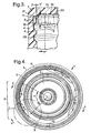
- Figure 4 shows an underneath view of the closure cap of Figure 1.
- Figure 1 corresponds to a section along the plane A-A in Figure 4.
- six reinforcing ribs 8 are arranged in a region 9, which follows immediately after the end 10 of the cap thread 6. Looking in the circumferential direction U, the region 9 adjoins the end 10 of the cap thread 6.
- Diametrically opposite second reinforcing ribs 18 are arranged. Ten second reinforcing ribs 18 extend through an angular region of about 150°. The second reinforcing ribs 18 have the same length L' in each case (see also Figure 2).
- Figure 5 shows an enlarged representation of the cut-out C from Figure 4.
- the inner faces 11 of the reinforcing ribs 8 follow an imaginery cylindrical face Z. Seen in the circumferential direction U, the reinforcing ribs 8 are arranged towards the end 10 of the cap thread 6.
- reinforcing ribs are also possible. For example, it is possible to distribute a plurality of equally long reinforcing ribs evenly over the circumference of the closure cap. Moreover, it is conceivable to provide reinforcing ribs, which extend from the cap thread up to the head plate.
- Figure 6a represents an embodiment, in which a large number of equally long reinforcing ribs 38 are arranged evenly over the whole circumference of the closure cap. The length l' of all reinforcing ribs is identical. The lower end of the reinforcing ribs 6 is arranged above the cap thread 6.
- reinforcing ribs 48 which extend from the lower edge of the cap thread 6 up to the head plate 2.
- the reinforcing ribs 48 are thereby arranged so that they lie outside the thread region used by the mouth thread 26 of the container.
- FIG. 7 shows a further alternative embodiment.
- the same reference symbols denote the same parts as in the previous Figures.
- the reinforcing ribs 58 extend up to the underside of an outer seal 32.
- the stop between the container mouth 21 and the closure cap 1 takes place via a front seal 33.
- Second reinforcing ribs 18 are arranged diametrically opposite the reinforcing ribs 58.
- the reinforcing ribs 18 abut on the start of the thread and thereby likewise have a braking effect. Because of the stiffening ribs 18, 58, any axial force applied in the event of overturning in the circumferential direction is evenly distributed.
Landscapes
- Engineering & Computer Science (AREA)
- Mechanical Engineering (AREA)
- Closures For Containers (AREA)
- Cosmetics (AREA)
- Road Signs Or Road Markings (AREA)
- Curing Cements, Concrete, And Artificial Stone (AREA)
Abstract
Description
- The invention concerns a closure cap, in particular a closure cap for a container containing carbonated beverages and having the features of the preamble of
Claim 1. - A large number of different embodiments of screw closure caps made of plastics material are used today for the closing of containers, such as e.g. beverage bottles.
- The final position, when the closure cap is in its fully screwed-on state, is determined on the one hand by the screwing-on, twisting moment and on the other hand, by the relationship between geometry of the closure cap and the container mouth. In particular, in the case of closure caps with internal lip seals, the final position of the closure cap is reached, when the inside of the cap top plate rests against the front side of the container mouth in the manner of a stop.
- One problem with such known closure caps consists in so-called overturning. If a user mistakenly tries to twist a mounted closure in the wrong direction using force (i.e. continuing to screw-on instead of unscrewing) there is a danger that the threads of the closure cap may snap over the threads of the container mouth. Thus, the closure cap may temporarily become disengaged from the container mouth. In particular, in the case of bottles with contents held under pressure, such as carbonated beverages for example, there is a danger that at the same time, the closure may fly off the bottle i.e. missiling. Such missiling can injure the user.
- Overturing safeguards have already been suggested, which prevent such overturning or in the event of overturning lead to a controlled gals blow-off. In WO95/21095 a braking element is described, which is arranged outside the thread path used to mount the closure and which, in the event of attempted overturning, engages with the thread of the container mouth. Overturning is thereby avoided.
- This solution has the disadvantage that the closure cap is greatly deformed in the radial direction in the event of overturning.
- Braking elements are also known, which define the end of the screwing-on process; thus from WO 90/10581 a braking element acting in the axial direction or in the circumferential direction is known, which towards the end of the screwing-on process engages with the start of the thread of the container mouth and so limits the screwing-on process.
- An aim of the present invention is to avoid the disadvantages of the known overturn protection arrangements. In particular, an aim of the invention is to create a closure cap, which effectively prevents overturning when the closure cap is mounted on the container mouth and at the same time effectively prevents deformation of the cap in the event of an attempt at overturning. The closure cap according to the invention, may be produced easily and can be used on conventional closure mouths.
- According to the invention these aims are solved by a closure cap having the features of the characterising part of
Claim 1. - As in conventional closure caps, the closure cap consists of a head plate and a more or less cylindrical cap skirt, which extends from the edge of the head plate. On the inside of the cap skirt a thread is provided, which can be brought into engagement with a complimentary thread on the container mouth.
- In the transition zone between the head plate and the cap skirt, reinforcing ribs, which extend up to the head plate, are arranged on the inside of the cap skirt. In the case of a closure cap having an outer seal arranged in the transition zone between cap skirt and head plate, the reinforcing ribs can only extend below the outer seal.
- The closure cap according to the invention has no additional braking elements, which limit the screwing-on movement. The end of the screwing-on movement is therefore determined by the fact that the inside of the head plate rests against the front side of the container mouth.
- The reinforcing ribs between the head plate and the cap skirt effectively counteract the overturning of the closure cap, even when increased force is applied. The reinforcing ribs stiffen the cap skirt and head plate in the transition zone, so that radial bulging of the cap skirt or excessive spreading between the head plate and cap skirt is avoided.
- According to a preferred embodiment of the invention, the reinforcing ribs are arranged in an area towards the head plate-side of the cap thread, as seen in the circumferential direction.
- Advantageously, the reinforcing ribs extend in the axial direction downwards at least as far as an imaginary screwing line, which corresponds more or less to the continuation of the cap thread. The reinforcing ribs thereby form an extension of the cap thread.
- Where the reinforcing ribs extend below the imaginary screwing line, a braking effect and an additional overturning safeguard is produced at the end of the screwing-on process.
- Advantageously, the reinforcing ribs extend more or less around an angular sector of 90°, which seen in the circumferential direction lies next to the end of the cap thread.
- In a further preferred embodiment additional, second reinforcing ribs can be provided in the transition region between head plate and cap skirt. These second reinforcing ribs are arranged outside the angular sector over which the reinforcing ribs extend. The length of the second reinforcing ribs in the axial direction is more or less equal. The second reinforcing ribs thus have a stiffening function and do not form any continuation of the cap thread. The second reinforcing ribs moreover, run on and so likewise limit the screwing-on movement.
- The reinforcing ribs and/or the second reinforcing ribs advantageously extend sufficiently inwards in the radial direction that their inner faces lie on an imaginary cylindrical section. The imaginary cylindrical section essentially corresponds to more or less the cylindrical outer face of the container mouth. In this way, the reinforcing ribs (and if necessary the second reinforcing ribs) additionally have a centring effect.
- The reinforcing ribs are particularly advantageous, where the closure cap is provided with a stop face on the inside of the head plate, which engages with the front side of the container mouth when the closure cap is mounted on the container. In this way, the screwing-on position is defined exactly. Forces acting on the head plate, which would normally result in a deformation of the head plate, are directed into the cap wall through the reinforcing ribs. Because of the reduced deformability of the head plate, the reinforcing ribs give both an exactly defined end position of the closure cap and also an overturning safeguard. In addition, an overturn safeguard such as that described in WO 095 /2105 can be used particularly advantageously. In this arrangement, the reinforcing ribs are arranged opposite the braking element e.g. two sets of reinforcing ribs can be provided. The content of WO 95/2105 is expressly incorporated by reference in the present application.
- The invention is described below in more detail by means of example embodiments explained by means of the drawings. They show:
- Figure 1 a cross section through a closure cap according to the invention along the plane A-A indicated in Figure 4,
- Figure 2 a schematic perspective representation of a cut-open closure cap mounted on a container mouth,
- Figure 3 an enlarged representation of the transition zone between head plate and cap skirt of a closure cap according to the invention mounted on a container mouth,
- Figure 4 an underneath view of the closure cap according to the invention,
- Figure 5 an enlarged representation of the cut-out section C from Figure 4,
- Figures 6a and 6b schematic representations of further embodiments of the invention, and
- Figure 7 a schematic representation of an embodiment with an outer seal.
-
- In Figure 1 a
closure cap 1 is shown in cross section. Theclosure cap 1 has ahead plate 2. From theedge 3 of thehead plate 2 extends a substantiallycylindrical cap skirt 4. Thecap skirt 4 is provided on itsinside 5 with acap thread 6. Thecap thread 6 is used for screwing theclosure cap 1 on to acontainer mouth 21 having a mouth thread 26 (see Figure 2). - The
closure cap 1 is provided with a conventionalinner seal 12. Theclosure cap 1 may also have aguarantee band 14. - On the inside of the
head plate 2 is astop 13, which comes into engagement with thefront side 23 of the container mouth 21 (see Figure 3) whenclosure cap 1 is mounted on the container. - In the
transition zone 7, between thehead plate 2 and thecap skirt 4, reinforcingribs 8 are provided on theinside 5. The reinforcingribs 8 extend in the axial direction up to thehead plate 2 and up to thestop 13 respectively. The reinforcingribs 8 stiffen thehead plate 2 and thecap skirt 4 in thetransition zone 7. Because of this stiffening, overturning of the closure cap is avoided. - The reinforcing
ribs 8 are arranged in aregion 9, which lies next to theend 10 of thecap thread 6, when viewed in the circumferential direction. The term the end of the thread is used here, and below, to describe the head plate-side end 10 of thecap thread 6. - The
length 1 of the reinforcingribs 8 has been chosen so that thelower edge 15 of the reinforcingribs 8 follow an imaginary screwing line S, which forms an extension of thecap thread 6. - Figure 2 is shows a perspective representation of a cut-
open closure cap 1 mounted on acontainer mouth 21. The same reference symbols as used in Figure 1 denote the same parts. - Figure 2 shows that the reinforcing
ribs 8 form an extension of thescrew thread 6 of theclosure cap 2 and follow themouth thread 26 of thecontainer mouth 21. - Moreover, in the right half of Figure 2 second reinforcing
ribs 18 are shown, which extend over a circumferential area of somewhat less than 180° and which are arranged diametrically opposite the reinforcingribs 8. The second reinforcingribs 18 are all of equal length 1'. The second reinforcingribs 18 have only a stiffening function and form no extension of thecap thread 6 of theclosure cap 1. - Figure 3 shows an enlarged.representation of a cross section through a cut-out of the
closure cap 1 in thetransition zone 7. - The
closure cap 1 is in the screwed-on position. Thestop 13 rests against thefront side 23 of thecontainer mouth 21. The reinforcingribs 8 each have adifferent length 1. Thelength 1 has been chosen so that with closure cap screwed on (i.e. with abutment of thefront side 23 on the stop 13) thelower edge 15 of the reinforcingribs 8 lies against themouth thread 26. In Figure 3 the stiffening effect of the reinforcingribs 8 is clear. When thestop 13 lies against thefront face 23, a further twisting of theclosure cap 1 is avoided, because thehead plate 2 cannot move in relation to thecap skirt 4. - The reinforcing
ribs 8 also have a centring function. The reinforcingribs 8 extend inwardly in the radial direction r, such that theirinner face 11 lies on an imaginary cylindrical cut-out Z. The cylindrical cut-out Z corresponds more or less to the cylindrical face Z', which is defined by thecontainer mouth 21. - Figure 4 shows an underneath view of the closure cap of Figure 1. Figure 1 corresponds to a section along the plane A-A in Figure 4. According to Figure 4, six reinforcing
ribs 8 are arranged in aregion 9, which follows immediately after theend 10 of thecap thread 6. Looking in the circumferential direction U, theregion 9 adjoins theend 10 of thecap thread 6. Diametrically opposite second reinforcingribs 18 are arranged. Ten second reinforcingribs 18 extend through an angular region of about 150°. The second reinforcingribs 18 have the same length L' in each case (see also Figure 2). - Figure 5 shows an enlarged representation of the cut-out C from Figure 4. The inner faces 11 of the reinforcing
ribs 8 follow an imaginery cylindrical face Z. Seen in the circumferential direction U, the reinforcingribs 8 are arranged towards theend 10 of thecap thread 6. - Of course, other configurations of the reinforcing ribs are also possible. For example, it is possible to distribute a plurality of equally long reinforcing ribs evenly over the circumference of the closure cap. Moreover, it is conceivable to provide reinforcing ribs, which extend from the cap thread up to the head plate. Figure 6a represents an embodiment, in which a large number of equally long reinforcing
ribs 38 are arranged evenly over the whole circumference of the closure cap. The length l' of all reinforcing ribs is identical. The lower end of the reinforcingribs 6 is arranged above thecap thread 6. Represented schematically in Figure 6b are reinforcingribs 48, which extend from the lower edge of thecap thread 6 up to thehead plate 2. The reinforcingribs 48 are thereby arranged so that they lie outside the thread region used by themouth thread 26 of the container. - The reinforcing
ribs cap skirt 4 andhead plate 2. - Figure 7 shows a further alternative embodiment. The same reference symbols denote the same parts as in the previous Figures.
- The reinforcing
ribs 58 extend up to the underside of anouter seal 32. The stop between thecontainer mouth 21 and theclosure cap 1 takes place via afront seal 33. - Second reinforcing
ribs 18 are arranged diametrically opposite the reinforcingribs 58. The reinforcingribs 18 abut on the start of the thread and thereby likewise have a braking effect. Because of the stiffeningribs
Claims (10)
- Closure cap (1), in particular for a container containing carbonated beverages,
having a head plate (2) and a substantially cylindrical cap skirt (4) extending from the edge (3) of the head plate (2), which skirt is provided on its inner side (5) with a cap thread (6), adapted for engagement with a mouth thread (26) of a container mouth (21),
characterised in that
reinforcing ribs (8; 38; 48; 58), which extend up to the head plate (2) or up to an outer seal (32) are provided on the inside (5) of the cap skirt (4) in the transition region (7) between the head plate(2) and the cap skirt (4). - Closure cap according to Claim 1, characterised in that the reinforcing ribs (8; 38; 48) are arranged in a region (9) towards the head plate-side end (10) of the cap thread (6) as viewed in the circumferential direction (U).
- Closure cap according to Claim 1 or claim 2,
characterised in that the reinforcing ribs (8; 38; 48) extend axially downwards at least as far as an imaginary screwing line (S), which corresponds more or less to a continuation of the cap thread (6). - Closure cap according to Claim 3, characterised in that the reinforcing ribs (8) extend in the axial direction downwards beyond the imaginary screwing line (S) .
- Closure cap according to one of the Claims 1 to 4, characterised in that the reinforcing ribs (8) are arranged in a region, which extends over an angular sector (α) of about 90°.
- Closure cap according to one of the Claims 1 to 5, characterised in that additional, second reinforcing ribs (18) are arranged in the transition region (7) between the head plate (2) and the cap skirt (4), outside the region (9), in which the reinforcing ribs (8) are situated.
- Closure cap according to Claim 6, characterised in that the second reinforcing ribs (18) each have the same length (1') in the axial direction (a).
- Closure cap according to one of the Claims 1 to 7, characterised in that the reinforcing ribs (8) and/or the second reinforcing ribs (18) extend in the radial inwardly in the direction r so that their inner faces (11) lie on an imaginary cylindrical cut-out (Z), which corresponds essentially to the cylindrical outer face (Z') of the container mouth (21).
- Closure cap according to one of the Claims 1 to 8, characterised in that the head plate (2) is provided with a stop face (13), which can be brought into engagement with the front side (23) of the container mouth (21).
- Closure cap according to one of the Claims 1 to 9, characterised in that a braking element is arranged opposite the reinforcing ribs, outside the thread region used with closure cap mounted.
Priority Applications (1)
| Application Number | Priority Date | Filing Date | Title |
|---|---|---|---|
| EP20000972992 EP1244591B1 (en) | 1999-11-08 | 2000-11-01 | Closure cap |
Applications Claiming Priority (4)
| Application Number | Priority Date | Filing Date | Title |
|---|---|---|---|
| EP99122306 | 1999-11-08 | ||
| EP19990122306 EP1097877A1 (en) | 1999-11-08 | 1999-11-08 | Closure cap |
| PCT/GB2000/004179 WO2001034491A1 (en) | 1999-11-08 | 2000-11-01 | Closure cap |
| EP20000972992 EP1244591B1 (en) | 1999-11-08 | 2000-11-01 | Closure cap |
Publications (2)
| Publication Number | Publication Date |
|---|---|
| EP1244591A1 EP1244591A1 (en) | 2002-10-02 |
| EP1244591B1 true EP1244591B1 (en) | 2004-08-11 |
Family
ID=8239353
Family Applications (2)
| Application Number | Title | Priority Date | Filing Date |
|---|---|---|---|
| EP19990122306 Withdrawn EP1097877A1 (en) | 1999-11-08 | 1999-11-08 | Closure cap |
| EP20000972992 Expired - Lifetime EP1244591B1 (en) | 1999-11-08 | 2000-11-01 | Closure cap |
Family Applications Before (1)
| Application Number | Title | Priority Date | Filing Date |
|---|---|---|---|
| EP19990122306 Withdrawn EP1097877A1 (en) | 1999-11-08 | 1999-11-08 | Closure cap |
Country Status (12)
| Country | Link |
|---|---|
| US (1) | US6913158B1 (en) |
| EP (2) | EP1097877A1 (en) |
| CN (1) | CN1170741C (en) |
| AT (1) | ATE273191T1 (en) |
| AU (1) | AU776897B2 (en) |
| BR (1) | BR0015389A (en) |
| CA (1) | CA2390308A1 (en) |
| DE (1) | DE60012982T2 (en) |
| ES (1) | ES2223600T3 (en) |
| MX (1) | MXPA02004575A (en) |
| NZ (1) | NZ518836A (en) |
| WO (1) | WO2001034491A1 (en) |
Cited By (1)
| Publication number | Priority date | Publication date | Assignee | Title |
|---|---|---|---|---|
| EP2800710B1 (en) | 2012-01-06 | 2016-08-03 | Closure Systems International Inc. | Linerless closure |
Families Citing this family (14)
| Publication number | Priority date | Publication date | Assignee | Title |
|---|---|---|---|---|
| FR2882731B1 (en) * | 2005-03-03 | 2007-05-18 | Bericap Sarl | CAP WITH ANTI-SABOTAGE FUNCTION AND DEGASSING SAFETY |
| US20100320168A1 (en) * | 2008-02-19 | 2010-12-23 | Martin Carey Bull | Child-resistant closure |
| MX2012000660A (en) * | 2009-07-31 | 2012-03-07 | Colgate Palmolive Co | Closure for a container. |
| USD621705S1 (en) | 2009-12-18 | 2010-08-17 | Intermarket Enterprises, Inc. | Bottle cap |
| USD621707S1 (en) | 2009-12-18 | 2010-08-17 | Intermarket Enterprises, Inc. | Bottle cap |
| USD621706S1 (en) | 2009-12-18 | 2010-08-17 | Intermarket Enterprises, Inc. | Bottle cap |
| US8789540B2 (en) * | 2010-03-18 | 2014-07-29 | Yong Jun Lee | Sealing ring structure of a cosmetic container |
| EP2468654B1 (en) * | 2010-12-23 | 2015-03-04 | Obrist Closures Switzerland GmbH | Closure for a container |
| MX2015000833A (en) * | 2012-07-20 | 2015-04-08 | Closure Systems Int Inc | Lightweight closure and container package. |
| WO2018129032A1 (en) | 2017-01-04 | 2018-07-12 | Berry Plastics Corporation | Closure |
| JP6554134B2 (en) * | 2017-04-13 | 2019-07-31 | ハスキー インジェクション モールディング システムズ リミテッドHusky Injection Molding Systems Limited | plug |
| US11059633B2 (en) | 2019-10-31 | 2021-07-13 | Cheer Pack North America | Flip-top closure for container |
| US11629986B2 (en) * | 2021-07-22 | 2023-04-18 | Curaleaf, Inc. | Squeeze doser with childproof cap |
| KR102756453B1 (en) * | 2024-04-02 | 2025-01-21 | 주식회사 경민산업 | Cosmetic lid assembly with open bottom packing |
Family Cites Families (14)
| Publication number | Priority date | Publication date | Assignee | Title |
|---|---|---|---|---|
| DE811919C (en) * | 1948-10-03 | 1951-08-23 | Fritz Gronbach | Lid closure |
| DE1482569A1 (en) * | 1965-07-01 | 1969-06-19 | Hopf A Metallwerke Kg | Screw cap closure |
| AU5220679A (en) * | 1978-11-06 | 1980-05-15 | Hicks, D.M. | Screw on cap with seal |
| US5133471A (en) * | 1989-03-14 | 1992-07-28 | Ultimos Desarrollos, S.A. | Stop devices for cap threads |
| BR9005774A (en) * | 1989-03-14 | 1991-08-06 | Crown Cork Ag | PLASTIC MATERIAL SCREW COVER |
| US5197621A (en) * | 1989-05-17 | 1993-03-30 | Crown Cork Ag | Screw cap made of plastics material |
| DE9117270U1 (en) * | 1991-08-09 | 1998-12-10 | Hertrampf, Michael, Dr., 30989 Gehrden | Screw cap for closing a bottle or the like. |
| FR2707328B1 (en) | 1993-07-09 | 1995-09-01 | Sogal France | Sliding leaf, and corner piece intended for the latter. |
| IL112387A (en) * | 1994-02-01 | 1997-07-13 | Crown Cork Ag | Screwable closure cap with security against over- tightening |
| US5667089A (en) * | 1994-03-23 | 1997-09-16 | Phoenix Closures, Inc. | Closure having a wrap-around seal |
| JP3467337B2 (en) * | 1994-12-06 | 2003-11-17 | 日本クラウンコルク株式会社 | Combination of screw cap and container made of synthetic resin with loosening prevention means |
| US6044994A (en) * | 1998-08-03 | 2000-04-04 | Phoenix Closures, Inc. | Sealing arrangement for closure caps having liners |
| EP0987191A1 (en) * | 1998-09-14 | 2000-03-22 | Crown Cork & Seal Technologies Corporation | Closure cap |
| US6382443B1 (en) * | 1999-04-28 | 2002-05-07 | Owens-Illinois Closure Inc. | Tamper-indicating closure with lugs on a stop flange for spacing the flange from the finish of a container |
-
1999
- 1999-11-08 EP EP19990122306 patent/EP1097877A1/en not_active Withdrawn
-
2000
- 2000-11-01 MX MXPA02004575A patent/MXPA02004575A/en active IP Right Grant
- 2000-11-01 EP EP20000972992 patent/EP1244591B1/en not_active Expired - Lifetime
- 2000-11-01 CN CNB008182655A patent/CN1170741C/en not_active Expired - Fee Related
- 2000-11-01 DE DE2000612982 patent/DE60012982T2/en not_active Expired - Fee Related
- 2000-11-01 ES ES00972992T patent/ES2223600T3/en not_active Expired - Lifetime
- 2000-11-01 US US10/129,553 patent/US6913158B1/en not_active Expired - Fee Related
- 2000-11-01 CA CA 2390308 patent/CA2390308A1/en not_active Abandoned
- 2000-11-01 AT AT00972992T patent/ATE273191T1/en not_active IP Right Cessation
- 2000-11-01 WO PCT/GB2000/004179 patent/WO2001034491A1/en not_active Ceased
- 2000-11-01 AU AU11549/01A patent/AU776897B2/en not_active Ceased
- 2000-11-01 NZ NZ518836A patent/NZ518836A/en unknown
- 2000-11-01 BR BR0015389A patent/BR0015389A/en not_active IP Right Cessation
Cited By (1)
| Publication number | Priority date | Publication date | Assignee | Title |
|---|---|---|---|---|
| EP2800710B1 (en) | 2012-01-06 | 2016-08-03 | Closure Systems International Inc. | Linerless closure |
Also Published As
| Publication number | Publication date |
|---|---|
| EP1244591A1 (en) | 2002-10-02 |
| WO2001034491A1 (en) | 2001-05-17 |
| BR0015389A (en) | 2002-07-02 |
| NZ518836A (en) | 2003-11-28 |
| DE60012982T2 (en) | 2005-08-18 |
| AU776897B2 (en) | 2004-09-23 |
| EP1097877A1 (en) | 2001-05-09 |
| DE60012982D1 (en) | 2004-09-16 |
| MXPA02004575A (en) | 2002-11-29 |
| CN1420831A (en) | 2003-05-28 |
| US6913158B1 (en) | 2005-07-05 |
| ATE273191T1 (en) | 2004-08-15 |
| AU1154901A (en) | 2001-06-06 |
| CA2390308A1 (en) | 2001-05-17 |
| ES2223600T3 (en) | 2005-03-01 |
| CN1170741C (en) | 2004-10-13 |
Similar Documents
| Publication | Publication Date | Title |
|---|---|---|
| EP1244591B1 (en) | Closure cap | |
| AU681931B2 (en) | Screw cap with over-tightening protection | |
| EP2240379B1 (en) | Closure with improved rotation-inhibiting projections | |
| CA1177443A (en) | Bottle finish and closure combination with venting slots | |
| US4903828A (en) | Bottle closure cap for two-component packages | |
| CN100436275C (en) | Closure assembly for wide-mouth container | |
| US5494174A (en) | Container with removal resistant closure | |
| US4382521A (en) | Vented closure | |
| WO2005092727A1 (en) | Container with securement means for a pack | |
| WO1990011944A1 (en) | A device for closing, with a security seal, a container of a rigid material, such as glass, by means of a screw cap of rigid thermoplastics material | |
| AU2002314361B2 (en) | Closure assembly with valve | |
| US4726482A (en) | Tamper indicating package and molded plastic closure therefor | |
| US7207453B2 (en) | Closure and a container for packing products | |
| EP2484600A1 (en) | Closure assembly for a container | |
| CA2630858A1 (en) | Jaw seals for container closure assemblies | |
| EP1627821B1 (en) | Screw cap for a container | |
| CA1296295C (en) | Two-piece screw closure for containers | |
| GB2275047A (en) | Fizzy drink safety cap | |
| EP4136035B1 (en) | Screw-cap closure | |
| EP1220792B1 (en) | Closure cap made of plastics material | |
| CA2242344C (en) | Bottle finish and closure cap with double screw thread | |
| AU691605C (en) | Container with removal resistant closure | |
| EP0244065A2 (en) | Threaded container and closure therefor | |
| WO1995015285A1 (en) | Vented snap-on, screw-off cap and container neck | |
| MXPA98008136A (en) | Cap to close a recipe |
Legal Events
| Date | Code | Title | Description |
|---|---|---|---|
| PUAI | Public reference made under article 153(3) epc to a published international application that has entered the european phase |
Free format text: ORIGINAL CODE: 0009012 |
|
| 17P | Request for examination filed |
Effective date: 20020503 |
|
| AK | Designated contracting states |
Kind code of ref document: A1 Designated state(s): AT BE CH CY DE DK ES FI FR GB GR IE IT LI LU MC NL PT SE TR |
|
| AX | Request for extension of the european patent |
Free format text: AL;LT;LV;MK;RO;SI |
|
| GRAP | Despatch of communication of intention to grant a patent |
Free format text: ORIGINAL CODE: EPIDOSNIGR1 |
|
| GRAS | Grant fee paid |
Free format text: ORIGINAL CODE: EPIDOSNIGR3 |
|
| GRAA | (expected) grant |
Free format text: ORIGINAL CODE: 0009210 |
|
| AK | Designated contracting states |
Kind code of ref document: B1 Designated state(s): AT BE CH CY DE DK ES FI FR GB GR IE IT LI LU MC NL PT SE TR |
|
| PG25 | Lapsed in a contracting state [announced via postgrant information from national office to epo] |
Ref country code: FI Free format text: LAPSE BECAUSE OF FAILURE TO SUBMIT A TRANSLATION OF THE DESCRIPTION OR TO PAY THE FEE WITHIN THE PRESCRIBED TIME-LIMIT Effective date: 20040811 Ref country code: CY Free format text: LAPSE BECAUSE OF FAILURE TO SUBMIT A TRANSLATION OF THE DESCRIPTION OR TO PAY THE FEE WITHIN THE PRESCRIBED TIME-LIMIT Effective date: 20040811 Ref country code: TR Free format text: LAPSE BECAUSE OF FAILURE TO SUBMIT A TRANSLATION OF THE DESCRIPTION OR TO PAY THE FEE WITHIN THE PRESCRIBED TIME-LIMIT Effective date: 20040811 Ref country code: NL Free format text: LAPSE BECAUSE OF FAILURE TO SUBMIT A TRANSLATION OF THE DESCRIPTION OR TO PAY THE FEE WITHIN THE PRESCRIBED TIME-LIMIT Effective date: 20040811 |
|
| REG | Reference to a national code |
Ref country code: GB Ref legal event code: FG4D |
|
| REG | Reference to a national code |
Ref country code: CH Ref legal event code: EP |
|
| RAP2 | Party data changed (patent owner data changed or rights of a patent transferred) |
Owner name: CROWN PACKAGING TECHNOLOGY, INC |
|
| REG | Reference to a national code |
Ref country code: CH Ref legal event code: NV Representative=s name: ISLER & PEDRAZZINI AG |
|
| REG | Reference to a national code |
Ref country code: IE Ref legal event code: FG4D |
|
| REF | Corresponds to: |
Ref document number: 60012982 Country of ref document: DE Date of ref document: 20040916 Kind code of ref document: P |
|
| NLT2 | Nl: modifications (of names), taken from the european patent patent bulletin |
Owner name: CROWN PACKAGING TECHNOLOGY, INC |
|
| PG25 | Lapsed in a contracting state [announced via postgrant information from national office to epo] |
Ref country code: LU Free format text: LAPSE BECAUSE OF NON-PAYMENT OF DUE FEES Effective date: 20041101 Ref country code: IE Free format text: LAPSE BECAUSE OF NON-PAYMENT OF DUE FEES Effective date: 20041101 |
|
| PG25 | Lapsed in a contracting state [announced via postgrant information from national office to epo] |
Ref country code: SE Free format text: LAPSE BECAUSE OF FAILURE TO SUBMIT A TRANSLATION OF THE DESCRIPTION OR TO PAY THE FEE WITHIN THE PRESCRIBED TIME-LIMIT Effective date: 20041111 Ref country code: GR Free format text: LAPSE BECAUSE OF FAILURE TO SUBMIT A TRANSLATION OF THE DESCRIPTION OR TO PAY THE FEE WITHIN THE PRESCRIBED TIME-LIMIT Effective date: 20041111 Ref country code: DK Free format text: LAPSE BECAUSE OF FAILURE TO SUBMIT A TRANSLATION OF THE DESCRIPTION OR TO PAY THE FEE WITHIN THE PRESCRIBED TIME-LIMIT Effective date: 20041111 |
|
| PG25 | Lapsed in a contracting state [announced via postgrant information from national office to epo] |
Ref country code: MC Free format text: LAPSE BECAUSE OF NON-PAYMENT OF DUE FEES Effective date: 20041130 |
|
| LTIE | Lt: invalidation of european patent or patent extension |
Effective date: 20040811 |
|
| NLV1 | Nl: lapsed or annulled due to failure to fulfill the requirements of art. 29p and 29m of the patents act | ||
| REG | Reference to a national code |
Ref country code: ES Ref legal event code: FG2A Ref document number: 2223600 Country of ref document: ES Kind code of ref document: T3 |
|
| ET | Fr: translation filed | ||
| PLBE | No opposition filed within time limit |
Free format text: ORIGINAL CODE: 0009261 |
|
| STAA | Information on the status of an ep patent application or granted ep patent |
Free format text: STATUS: NO OPPOSITION FILED WITHIN TIME LIMIT |
|
| REG | Reference to a national code |
Ref country code: IE Ref legal event code: MM4A |
|
| 26N | No opposition filed |
Effective date: 20050512 |
|
| REG | Reference to a national code |
Ref country code: CH Ref legal event code: NV Representative=s name: HEPP, WENGER & RYFFEL AG Ref country code: CH Ref legal event code: PUE Owner name: OBRIST CLOSURES SWITZERLAND GMBH Free format text: CROWN PACKAGING TECHNOLOGY, INC#11535 SOUTH CENTRAL AVENUE#ALSIP, IL 60803-2599 (US) -TRANSFER TO- OBRIST CLOSURES SWITZERLAND GMBH#ROEMERSTRASSE 83#4153 REINACH (CH) |
|
| REG | Reference to a national code |
Ref country code: GB Ref legal event code: 732E |
|
| PGFP | Annual fee paid to national office [announced via postgrant information from national office to epo] |
Ref country code: DE Payment date: 20061026 Year of fee payment: 7 |
|
| PGFP | Annual fee paid to national office [announced via postgrant information from national office to epo] |
Ref country code: GB Payment date: 20061101 Year of fee payment: 7 |
|
| PGFP | Annual fee paid to national office [announced via postgrant information from national office to epo] |
Ref country code: FR Payment date: 20061108 Year of fee payment: 7 |
|
| PGFP | Annual fee paid to national office [announced via postgrant information from national office to epo] |
Ref country code: AT Payment date: 20061113 Year of fee payment: 7 |
|
| PGFP | Annual fee paid to national office [announced via postgrant information from national office to epo] |
Ref country code: IT Payment date: 20061130 Year of fee payment: 7 |
|
| PGFP | Annual fee paid to national office [announced via postgrant information from national office to epo] |
Ref country code: ES Payment date: 20061222 Year of fee payment: 7 |
|
| PGFP | Annual fee paid to national office [announced via postgrant information from national office to epo] |
Ref country code: BE Payment date: 20070118 Year of fee payment: 7 |
|
| PGFP | Annual fee paid to national office [announced via postgrant information from national office to epo] |
Ref country code: CH Payment date: 20070212 Year of fee payment: 7 |
|
| REG | Reference to a national code |
Ref country code: FR Ref legal event code: CD Ref country code: FR Ref legal event code: TP |
|
| BECH | Be: change of holder |
Owner name: *OBRIST CLOSURES SWITZERLAND G.M.B.H. Effective date: 20060921 |
|
| BECN | Be: change of holder's name |
Owner name: *OBRIST CLOSURES SWITZERLAND G.M.B.H. Effective date: 20060921 |
|
| PG25 | Lapsed in a contracting state [announced via postgrant information from national office to epo] |
Ref country code: PT Free format text: LAPSE BECAUSE OF NON-PAYMENT OF DUE FEES Effective date: 20050111 |
|
| BERE | Be: lapsed |
Owner name: *OBRIST CLOSURES SWITZERLAND G.M.B.H. Effective date: 20071130 |
|
| GBPC | Gb: european patent ceased through non-payment of renewal fee |
Effective date: 20071101 |
|
| PG25 | Lapsed in a contracting state [announced via postgrant information from national office to epo] |
Ref country code: CH Free format text: LAPSE BECAUSE OF NON-PAYMENT OF DUE FEES Effective date: 20071130 Ref country code: LI Free format text: LAPSE BECAUSE OF NON-PAYMENT OF DUE FEES Effective date: 20071130 |
|
| REG | Reference to a national code |
Ref country code: CH Ref legal event code: PL |
|
| PG25 | Lapsed in a contracting state [announced via postgrant information from national office to epo] |
Ref country code: AT Free format text: LAPSE BECAUSE OF NON-PAYMENT OF DUE FEES Effective date: 20071101 |
|
| PG25 | Lapsed in a contracting state [announced via postgrant information from national office to epo] |
Ref country code: BE Free format text: LAPSE BECAUSE OF NON-PAYMENT OF DUE FEES Effective date: 20071130 |
|
| PG25 | Lapsed in a contracting state [announced via postgrant information from national office to epo] |
Ref country code: DE Free format text: LAPSE BECAUSE OF NON-PAYMENT OF DUE FEES Effective date: 20080603 |
|
| REG | Reference to a national code |
Ref country code: FR Ref legal event code: ST Effective date: 20080930 |
|
| PG25 | Lapsed in a contracting state [announced via postgrant information from national office to epo] |
Ref country code: GB Free format text: LAPSE BECAUSE OF NON-PAYMENT OF DUE FEES Effective date: 20071101 |
|
| REG | Reference to a national code |
Ref country code: ES Ref legal event code: FD2A Effective date: 20071102 |
|
| PG25 | Lapsed in a contracting state [announced via postgrant information from national office to epo] |
Ref country code: FR Free format text: LAPSE BECAUSE OF NON-PAYMENT OF DUE FEES Effective date: 20071130 Ref country code: ES Free format text: LAPSE BECAUSE OF NON-PAYMENT OF DUE FEES Effective date: 20071102 |
|
| PG25 | Lapsed in a contracting state [announced via postgrant information from national office to epo] |
Ref country code: IT Free format text: LAPSE BECAUSE OF NON-PAYMENT OF DUE FEES Effective date: 20071101 |