EP1097877A1 - Closure cap - Google Patents
Closure cap Download PDFInfo
- Publication number
- EP1097877A1 EP1097877A1 EP19990122306 EP99122306A EP1097877A1 EP 1097877 A1 EP1097877 A1 EP 1097877A1 EP 19990122306 EP19990122306 EP 19990122306 EP 99122306 A EP99122306 A EP 99122306A EP 1097877 A1 EP1097877 A1 EP 1097877A1
- Authority
- EP
- European Patent Office
- Prior art keywords
- cap
- reinforcing ribs
- head plate
- thread
- closure cap
- Prior art date
- Legal status (The legal status is an assumption and is not a legal conclusion. Google has not performed a legal analysis and makes no representation as to the accuracy of the status listed.)
- Withdrawn
Links
Images


Classifications
-
- B—PERFORMING OPERATIONS; TRANSPORTING
- B65—CONVEYING; PACKING; STORING; HANDLING THIN OR FILAMENTARY MATERIAL
- B65D—CONTAINERS FOR STORAGE OR TRANSPORT OF ARTICLES OR MATERIALS, e.g. BAGS, BARRELS, BOTTLES, BOXES, CANS, CARTONS, CRATES, DRUMS, JARS, TANKS, HOPPERS, FORWARDING CONTAINERS; ACCESSORIES, CLOSURES, OR FITTINGS THEREFOR; PACKAGING ELEMENTS; PACKAGES
- B65D41/00—Caps, e.g. crown caps or crown seals, i.e. members having parts arranged for engagement with the external periphery of a neck or wall defining a pouring opening or discharge aperture; Protective cap-like covers for closure members, e.g. decorative covers of metal foil or paper
- B65D41/02—Caps or cap-like covers without lines of weakness, tearing strips, tags, or like opening or removal devices
- B65D41/04—Threaded or like caps or cap-like covers secured by rotation
- B65D41/0471—Threaded or like caps or cap-like covers secured by rotation with means for positioning the cap on the container, or for limiting the movement of the cap, or for preventing accidental loosening of the cap
-
- Y—GENERAL TAGGING OF NEW TECHNOLOGICAL DEVELOPMENTS; GENERAL TAGGING OF CROSS-SECTIONAL TECHNOLOGIES SPANNING OVER SEVERAL SECTIONS OF THE IPC; TECHNICAL SUBJECTS COVERED BY FORMER USPC CROSS-REFERENCE ART COLLECTIONS [XRACs] AND DIGESTS
- Y02—TECHNOLOGIES OR APPLICATIONS FOR MITIGATION OR ADAPTATION AGAINST CLIMATE CHANGE
- Y02W—CLIMATE CHANGE MITIGATION TECHNOLOGIES RELATED TO WASTEWATER TREATMENT OR WASTE MANAGEMENT
- Y02W90/00—Enabling technologies or technologies with a potential or indirect contribution to greenhouse gas [GHG] emissions mitigation
- Y02W90/10—Bio-packaging, e.g. packing containers made from renewable resources or bio-plastics
Definitions
- the invention relates to a closure cap, in particular one Cap for a container with carbonated drinks with the features of the preamble of claim 1.
- Screw caps made of plastic are now in one Variety of different embodiments for closing of containers such as Beverage bottles used.
- the final position in which the cap is screwed on Condition is determined on the one hand by the screwing torque and on the other hand by the relationship between Geometry of the cap and the container mouth determined. Especially with caps with internal lip seals the end position of the cap is reached when the Inside of the cap base in the manner of a stop on the front side the container mouth is in contact.
- a problem with such known caps is so-called overturning. If a user tries incorrectly, with force applied an attached closure in to turn the wrong direction (i.e. continue to unscrew instead of unscrew) there is a risk that the threads of the cap Snap over the threads of the container mouth.
- the cap can be temporarily out of engagement with the container mouth devices. Especially for bottles with pressure Contents such as carbonated drinks there is a risk that the closure will come off. Jumping off Closures can injure the user.
- braking elements are known which mark the end of the screwing-on process define; is from WO 90/10581 in the axial direction or known braking element acting in the circumferential direction, towards the end of the screwing process with the beginning of the thread the container mouth comes into engagement and thus the unscrewing process limited.
- the cap should be easy to manufacture and can be used on conventional container mouths.
- the closure cap consists of a Head plate and an approximately cylindrical apron that extends extends from the edge of the head plate.
- a cap thread is provided, which with a muzzle thread can be brought into engagement at a container mouth.
- the closure cap according to the invention has no additional Brake elements that limit the unscrewing movement.
- the end the screwing motion is determined by the inside the head plate strikes the front of the container mouth.
- the reinforcing ribs between the head plate and the cap apron cause overtightening the cap counteracted effectively even with increased effort becomes.
- the reinforcing ribs stiffen the cap apron and head plate in the transition area, so that a radial bulge of the Cap apron or an excessive spreading of the head plate and cap apron is avoided.
- the reinforcing ribs seen in an area in the circumferential direction arranged after the end of the cap thread on the head plate side.
- the reinforcing ribs advantageously extend axially Direction down to at least an imaginary helix, which corresponds approximately to the continuation of the cap thread.
- the reinforcing ribs thus form an extension of the cap thread.
- the reinforcing ribs advantageously extend approximately over one Angular range of 90 ° seen in the circumferential direction connects to the end of the cap thread.
- second reinforcement ribs in the transition area be provided between the head plate and cap apron.
- This second reinforcing ribs are outside the angular range arranged, over which the reinforcing ribs extend.
- the length of the second reinforcing ribs is in the axial direction each about the same size. So the second reinforcement ribs have a stiffening function and do not form a continuation of the cap thread.
- the second reinforcement ribs can also open the thread start of the container mouth and thus the screwing movement also limit.
- the reinforcing ribs and / or the second reinforcing ribs extend advantageously in the radial direction as far inside that their inner surfaces on an imaginary cylinder section lie.
- the imaginary cylinder section corresponds essentially about the cylindrical outer surface of the Container mouth. In this way the reinforcing ribs have and possibly the second reinforcing ribs also have a centering effect.
- the reinforcing ribs are particularly advantageous when the closure cap on the inside of the head plate with a stop surface is provided when the cap is attached is in engagement with the end face of the container mouth. On in this way the screw-on position is precisely defined. On the Forces acting on the headstock, which normally lead to deformation the top plate could lead over the reinforcing ribs directed into the cap wall.
- the reinforcement ribs lead due to the reduced deformability of the head plate both to a more precisely defined end position of the closure cap as well as an overturn protection. Can be particularly advantageous also an overturn protection as described in WO 95/2105 be used.
- the stiffening ribs are opposite arranged the braking element. For example, two stiffening ribs be provided. The content of WO 95/2105 is explicit included in the present application.
- a closure cap 1 is shown in cross section in FIG.
- the closure cap 1 has a head plate 2. From edge 3 the head plate 2 extends an approximately cylindrical cap apron 4.
- the cap apron 4 is on its inside 5 with provided with a cap thread 6.
- the cap thread 6 is used for Screw the cap 1 onto a container mouth 21 with a muzzle thread 26 (see Figure 2).
- the cap 1 is in the usual way with an inner seal 12 provided.
- the cap can also be a guarantee band 14 have.
- a stop 13 is provided on the inside of the head plate 2, the with the cap 1 with the front 23 of the container mouth 21 engages (see Figure 3).
- the reinforcing ribs 8 extend in the axial direction a up to the head plate 2 or up to the stop 13.
- the reinforcing ribs 8 stiffen the head plate 2 and the cap apron 4 in the transition area 7. Due to this stiffening, a Avoid overtightening the cap.
- the reinforcing ribs 8 are arranged in an area 9 which connects to the end 10 of the cap thread 6 in the circumferential direction. With the end of the thread, here and in the following it will be understood end plate end 10 of the cap thread 6.
- the length 1 of the reinforcing ribs 8 is chosen so that the lower edge 15 of the reinforcing ribs 8 of an imaginary helix S follows, which is an extension of the cap thread 6 forms.
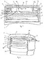
- Figure 2 is a perspective view of a cut, cap 1 placed on a container mouth 21 shown.
- the same reference numerals as in Figure 1 designate the same Parts.
- Figure 2 shows that the reinforcing ribs 8 are an extension of the screw thread 6 of the cap 2 and the Muzzle thread 26 follow the container mouth 21.
- second reinforcing ribs 18 which extends over a circumferential range of extend a little less than 180 ° and the diametrically opposite the reinforcing ribs 8 are arranged.
- the length l 'of the second Reinforcing ribs 18 are the same size.
- the second reinforcement ribs 18 have only a stiffening function and do not form an extension of the cap thread 6 of the closure cap 1.
- FIG. 3 shows an enlarged section of the Cap 1 in the transition area 7 shown in cross section.
- the sealing cap 1 is in the screwed-on position.
- the Stop 13 lies on the end face 23 of the container mouth 21 on.
- the reinforcing ribs 8 have a different length l. The length l is selected so that when the cap is screwed on (i.e. when the end face 23 abuts the stop 13) the lower edge 15 of the reinforcing ribs 8 on the muzzle thread 26 is present. In Figure 3, the stiffening effect of the reinforcing ribs 8 clearly. If the stop 13 on the end face 23 is present, further turning of the closure cap 1 is avoided, because the top plate 2 is in relation to the cap apron 4th can't move.
- the reinforcing ribs 8 also have a centering function.
- the reinforcing ribs 8 extend in the radial direction r so far inwards that its inner surface 11 on an imaginary Cylinder cutout Z lies.
- the cylinder cutout Z corresponds approximately to the cylinder surface Z 'through the container mouth 21 is defined.
- FIG. 4 is a bottom view of the closure cap from FIG. 1 shown.
- Figure 1 corresponds to a section along the plane A-A in Figure 4.
- the area 9 extends over a Angle a of about 90 °.
- the area 9 is U in the circumferential direction seen adjacent to the end 10 of the cap thread 6.
- Second reinforcing ribs 18 are arranged diametrically opposite one another. Ten second reinforcing ribs 18 extend approximately over an angular range of 150 °.
- the second reinforcement ribs 18 each have the same length 1 '(see also Figure 2).
- FIG. 5 shows an enlarged view of section C from Figure 4.
- the inner surfaces 11 of the reinforcing ribs 8 follow an imaginary cylindrical surface Z.
- the reinforcing ribs 8 are seen in the circumferential direction U after the end 10 of the cap thread 6 arranged.
- FIG. 6a An exemplary embodiment is shown in FIG. 6a shown schematically, in which a plurality of equal lengths Reinforcing ribs 38 evenly over the entire circumference of the Closure cap are arranged. The length l '' of all reinforcing ribs is identical. The lower end of the reinforcement ribs 6 is arranged above the cap thread 6.
- FIG. 6b schematically shows reinforcing ribs 48 which from the upper edge of the cap thread 6 to the top plate 2 extend. The reinforcing ribs 48 are arranged so that they are outside of the mouth thread 26 of the container used thread range.
- the reinforcing ribs 38, 48 of FIGS. 6a and 6b also lead to the desired stiffening between cap apron 4 and Head plate 2.
- FIG. 7 shows a further alternative embodiment.
- the same reference numerals designate the same parts as in the previous ones Characters.
- the reinforcing ribs 58 extend to the bottom an outer seal 32.
- the stop between the container mouth 21 and the closure cap 1 is made via an end seal 33.
- Second reinforcing ribs 18 are diametrically opposite the reinforcing rib 18 arranged.
- the reinforcing ribs 18 run on the thread start and also form a braking effect. Due to the stiffening ribs 18, 58, the axial force evenly distributed when turning in the circumferential direction.
Abstract
Description
Die Erfindung betrifft eine Verschlusskappe, insbesondere eine
Verschlusskappe für einen Behälter mit kohlesäurehaltigen Getränken
mit den Merkmalen des Oberbegriffs von Patentanspruch 1.The invention relates to a closure cap, in particular one
Cap for a container with carbonated drinks
with the features of the preamble of
Schraubverschlusskappen aus Kunststoff werden heute in einer Vielzahl von verschiedenen Ausführungsformen zum Verschliessen von Behältern wie z.B. Getränkeflaschen eingesetzt.Screw caps made of plastic are now in one Variety of different embodiments for closing of containers such as Beverage bottles used.
Die endgültige Position, in der sich die Verschlusskappe in aufgeschraubtem Zustand befindet, wird einerseits durch das Auf-schraubdrehmoment und andererseits durch das Verhältnis zwischen Geometrie der Verschlusskappe und der Behältermündung bestimmt. Insbesondere bei Verschlusskappen mit innenliegenden Lippendichtungen wird die Endlage der Verschlusskappe erreicht, wenn die Innenseite des Kappenbodens in Art eines Anschlags an der Stirnseite der Behältermündung anliegt.The final position in which the cap is screwed on Condition is determined on the one hand by the screwing torque and on the other hand by the relationship between Geometry of the cap and the container mouth determined. Especially with caps with internal lip seals the end position of the cap is reached when the Inside of the cap base in the manner of a stop on the front side the container mouth is in contact.
Ein Problem bei solchen bekannten Verschlusskappen besteht im sogenannten Überdrehen. Wenn ein Benutzer fälschlicherweise versucht, unter Kraftaufwendung einen aufgesetzten Verschluss in die falsche Richtung zu drehen (d.h. weiter auf- statt abzuschrauben) besteht die Gefahr, dass die Gewinde der Verschlusskappe über die Gewinde der Behältermündung schnappen. Die Verschlusskappe kann so zeitweise ausser Eingriff mit der Behältermündung geraten. Insbesondere bei Flaschen mit unter Druck stehendem Inhalt wie beispielsweise kohlesäurehaltigen Getränken besteht dabei die Gefahr, dass der Verschluss abspringt. Abspringende Verschlüsse können den Benutzer verletzen.A problem with such known caps is so-called overturning. If a user tries incorrectly, with force applied an attached closure in to turn the wrong direction (i.e. continue to unscrew instead of unscrew) there is a risk that the threads of the cap Snap over the threads of the container mouth. The cap can be temporarily out of engagement with the container mouth devices. Especially for bottles with pressure Contents such as carbonated drinks there is a risk that the closure will come off. Jumping off Closures can injure the user.
Es wurde bereits vorgeschlagen, Überdrehsicherungen vorzusehen, die ein solches Überdrehen verhindern bzw. die bei einem Überdrehen zu einem kontrollierten Gasablass führen. In WO 95/2105 wird ein Bremselement beschrieben, welches ausserhalb des bei aufgesetztem Verschluss benutztem Gewindegangs angeordnet ist und welches bei versuchtem Überdrehen mit dem Gewindeende der Behältermündung in Eingriff gerät. Ein Überdrehen wird dabei vermieden.It has already been proposed to provide overturn protection devices that prevent such over-tightening or that when over-tightening lead to a controlled gas discharge. In WO 95/2105 a braking element is described, which is outside the at attached closure is used thread and which if you try to overtighten with the thread end of the Container mouth engages. Overwinding will avoided.
Diese Lösung ist mit dem Nachteil behaftet, dass die Verschlusskappe beim Überdrehen in radialer Richtung stark deformiert wird.This solution has the disadvantage that the closure cap badly deformed when turning in the radial direction becomes.
Ausserdem sind Bremselemente bekannt, welche das Ende des Aufschraubvorgangs definieren; so ist aus WO 90/10581 ein in Achsrichtung oder in Umfangsrichtung wirkendes Bremselement bekannt, das gegen das Ende des Aufschraubvorgangs mit dem Gewindeanfang der Behältermündung in Eingriff gerät und so den Aufschraubvorgang begrenzt.In addition, braking elements are known which mark the end of the screwing-on process define; is from WO 90/10581 in the axial direction or known braking element acting in the circumferential direction, towards the end of the screwing process with the beginning of the thread the container mouth comes into engagement and thus the unscrewing process limited.
Es ist eine Aufgabe der vorliegenden Erfindung, die Nachteile des Bekannten zu vermeiden, insbesondere eine Verschlusskappe zu schaffen, welche wirkungsvoll ein Überdrehen bei aufgesetzter Verschlusskappe verhindert, und gleichzeitig bei einem Versuch des Überdrehens der Verformung der Kappe wirksam entgegenwirkt. Die Verschlusskappe soll auf einfache Weise herstellbar sein und auf herkömmlichen Behältermündungen einsetzbar sein.It is an object of the present invention to address the disadvantages to avoid the known, in particular a closure cap create which effectively over-tighten when attached Prevents cap, and at the same time during an attempt counteracting the deformation of the cap effectively. The cap should be easy to manufacture and can be used on conventional container mouths.
Erfindungsgemäss werden diese Aufgaben mit einer Verschlusskappe
mit den Merkmalen des kennzeichnenden Teils von Anspruch 1 gelöst.According to the invention, these tasks are performed with a sealing cap
solved with the features of the characterizing part of
Die Verschlusskappe besteht in an sich bekannter Weise aus einer Kopfplatte und einer etwa zylindrischen Kappenschürze, die sich vom Rand der Kopfplatte erstreckt. An der Innenseite der Kappenschürze ist ein Kappengewinde vorgesehen, welches mit einem Mündungsgewinde an einer Behältermündung in Eingriff bringbar ist.In a manner known per se, the closure cap consists of a Head plate and an approximately cylindrical apron that extends extends from the edge of the head plate. On the inside of the cap apron a cap thread is provided, which with a muzzle thread can be brought into engagement at a container mouth.
Im Übergangsbereich zwischen der Kopfplatte und der Kappenschürze sind an der Innenseite der Kappenschürze Verstärkungsrippen vorgesehen, die sich bis an die Kopfplatte erstrecken. Im Fall einer Verschlusskappe mit einer im Uebergangsbereich zwischen Kappenschürze und Kopfplatte angeordneten Aussendichtung können sich die Verstärkungsrippen auch nur bis unterhalb die Aussendichtung erstrecken.In the transition area between the head plate and the cap apron are reinforcement ribs on the inside of the cap apron provided that extend to the head plate. In the case a cap with one in the transition area between Cap apron and head plate arranged outer seal can the reinforcing ribs also just below the outer seal extend.
Die erfindungsgemässe Verschlusskappe weist keine zusätzlichen Bremselemente auf, die die Aufschraubbewegung begrenzen. Das Ende der Aufschraubbewegung wird dadurch bestimmt, dass die Innenseite der Kopfplatte an der Stirnseite der Behältermündung anschlägt.The closure cap according to the invention has no additional Brake elements that limit the unscrewing movement. The end the screwing motion is determined by the inside the head plate strikes the front of the container mouth.
Die Verstärkungsrippen zwischen der Kopfplatte und der Kappenschürze führen dazu, dass dem Überdrehen der Verschlusskappe auch mit erhöhtem Kraftaufwand wirkungsvoll entgegengewirkt wird. Die Verstärkungsrippen versteifen Kappenschürze und Kopfplatte im Übergangsbereich, so dass eine radiale Ausbeulung der Kappenschürze oder ein übermässiges Aufspreizen von Kopfplatte und Kappenschürze vermieden wird.The reinforcing ribs between the head plate and the cap apron cause overtightening the cap counteracted effectively even with increased effort becomes. The reinforcing ribs stiffen the cap apron and head plate in the transition area, so that a radial bulge of the Cap apron or an excessive spreading of the head plate and cap apron is avoided.
Gemäss einem bevorzugten Ausführungsbeispiel der Erfindung sind die Verstärkungsrippen in Umfangsrichtung gesehen in einem Bereich nach dem kopfplattenseitigen Ende des Kappengewindes angeordnet.According to a preferred embodiment of the invention the reinforcing ribs seen in an area in the circumferential direction arranged after the end of the cap thread on the head plate side.
Vorteilhaft erstrecken sich die Verstärkungsrippen in axialer Richtung nach unten bis wenigstens zu einer gedachten Schraubenlinie, die etwa der Fortsetzung des Kappengewindes entspricht. The reinforcing ribs advantageously extend axially Direction down to at least an imaginary helix, which corresponds approximately to the continuation of the cap thread.
Damit bilden die Verstärkungsrippen eine Verlängerung des Kappengewindes.The reinforcing ribs thus form an extension of the cap thread.
Bei sich bis unterhalb der gedachten Schraubenlinie erstreckenden Verstärkungsrippen wird zusätzlich ein Bremseffekt am Ende des Aufschraubvorgangs bzw. eine zusätzliche Überdrehsicherung bewirkt.When extending to below the imaginary helix Reinforcing ribs will also have a braking effect at the end of the unscrewing process or an additional overturn protection causes.
Die Verstärkungsrippen erstrecken sich vorteilhaft etwa über einen Winkelbereich von 90°, der sich in Umfangsrichtung gesehen an das Ende des Kappengewindes anschliesst.The reinforcing ribs advantageously extend approximately over one Angular range of 90 ° seen in the circumferential direction connects to the end of the cap thread.
In einem weiteren bevorzugten Ausführungsbeispiel können ausserdem zusätzliche, zweite Verstärkungsrippen im Übergangsbereich zwischen Kopfplatte und Kappenschürze vorgesehen sein. Diese zweiten Verstärkungsrippen sind ausserhalb des Winkelbereichs angeordnet, über welchen sich die Verstärkungsrippen erstrecken. Die Länge der zweiten Verstärkungsrippen ist in axialer Richtung je etwa gleich gross. Die zweiten Verstärkungsrippen haben also eine Versteifungsfunktion und bilden keine Fortsetzung des Kappengewindes. Die zweiten Verstärkungsrippen können ausserdem auf dem Gewindeanfang der Behältermündung auflaufen und so die Aufschraubbewegng ebenfalls begrenzen.In a further preferred embodiment, in addition additional, second reinforcement ribs in the transition area be provided between the head plate and cap apron. This second reinforcing ribs are outside the angular range arranged, over which the reinforcing ribs extend. The length of the second reinforcing ribs is in the axial direction each about the same size. So the second reinforcement ribs have a stiffening function and do not form a continuation of the cap thread. The second reinforcement ribs can also open the thread start of the container mouth and thus the screwing movement also limit.
Die Verstärkungsrippen und/oder die zweiten Verstärkungsrippen erstrecken sich ausserdem vorteilhaft in radialer Richtung soweit nach innen, dass ihre Innenflächen auf einem gedachten Zylinderabschnitt liegen. Der gedachte Zylinderabschnitt entspricht im wesentlichen etwa der zylindrischen Aussenfläche der Behältermündung. Auf diese Weise haben die Verstärkungsrippen und ggf. die zweiten Verstärkungsrippen ausserdem eine Zentrie-rungswirkung. The reinforcing ribs and / or the second reinforcing ribs extend advantageously in the radial direction as far inside that their inner surfaces on an imaginary cylinder section lie. The imaginary cylinder section corresponds essentially about the cylindrical outer surface of the Container mouth. In this way the reinforcing ribs have and possibly the second reinforcing ribs also have a centering effect.
Die Verstärkungsrippen sind besonders vorteilhaft, wenn die Verschlusskappe an der Innenseite der Kopfplatte mit einer Anschlagfläche versehen ist, die bei aufgesetzter Verschlusskappe in Eingriff mit der Stirnseite der Behältermündung steht. Auf diese Weise wird die Aufschraublage genau definiert. Auf die Kopfplatte wirkende Kräfte, welche normalerweise zu einer Verformung der Kopfplatte führen könnten, werden über die Verstärkungsrippen in die Kappenwand geleitet. Die Verstärkungsrippen führen auf Grund der reduzierten Verformbarkeit der Kopfplatte sowohl zu einer genauer definierten Endlage der Verschlusskappe als auch zu einer Überdrehsicherung. Besonders vorteilhaft kann ausserdem eine Ueberdrehsicherung wie in WO 95/2105 beschrieben eingesetzt werden. Die Versteifungsrippen sind dabei gegenüber dem Bremselement angeordnet. Es können z.B. zwei Versteifungsrippen vorgesehen sein. Der Inhalt der WO 95/2105 wird ausdrücklich in die vorliegende Anmeldung aufgenommen.The reinforcing ribs are particularly advantageous when the closure cap on the inside of the head plate with a stop surface is provided when the cap is attached is in engagement with the end face of the container mouth. On in this way the screw-on position is precisely defined. On the Forces acting on the headstock, which normally lead to deformation the top plate could lead over the reinforcing ribs directed into the cap wall. The reinforcement ribs lead due to the reduced deformability of the head plate both to a more precisely defined end position of the closure cap as well as an overturn protection. Can be particularly advantageous also an overturn protection as described in WO 95/2105 be used. The stiffening ribs are opposite arranged the braking element. For example, two stiffening ribs be provided. The content of WO 95/2105 is explicit included in the present application.
Die Erfindung wird im folgenden anhand von Ausführungsbeispielen und anhand der Zeichnungen näher erläutert. Es zeigen:
Figur 1- einen Querschnitt durch eine erfindungsgemässe Verschlusskappe
entlang der Ebene A-A aus
Figur 4, Figur 2- eine schematische perspektivische Darstellung einer aufgeschnittenen erfindungsgemässen Verschlusskappe auf einer Behältermündung,
- Figur 3
- eine vergrösserte Darstellung einer erfindungsgemässen Verschlusskappe auf einer Behältermündung im Übergangsbereich zwischen Kopfplatte und Kappenschürze,
Figur 4- einer Unteransicht der erfindungsgemässen Verschlusskappe,
Figur 5- eine vergrösserte Darstellung des Ausschnitts C aus
Figur 4, - Figuren 6a und 6b
- schematische Darstellungen von weiteren Ausführungsbeispielen, und
Figur 7- schematische Darstellung eines Ausführungsbeispiels mit Aussendichtung.
- Figure 1
- 3 shows a cross section through a closure cap according to the invention along the plane AA from FIG. 4,
- Figure 2
- 2 shows a schematic perspective illustration of a cut-open closure cap according to the invention on a container mouth,
- Figure 3
- 2 shows an enlarged view of a closure cap according to the invention on a container mouth in the transition region between the top plate and the cap apron,
- Figure 4
- a bottom view of the closure cap according to the invention,
- Figure 5
- 3 shows an enlarged view of section C from FIG. 4,
- Figures 6a and 6b
- schematic representations of further embodiments, and
- Figure 7
- schematic representation of an embodiment with outer seal.
In Figur 1 ist im Querschnitt eine Verschlusskappe 1 gezeigt.
Die Verschlusskappe 1 weist eine Kopfplatte 2 auf. Vom Rand 3
der Kopfplatte 2 erstreckt sich eine etwa zylindrische Kappenschürze
4. Die Kappenschürze 4 ist auf ihrer Innenseite 5 mit
einem Kappengewinde 6 versehen. Das Kappengewinde 6 dient zum
Aufschrauben der Verschlusskappe 1 auf eine Behältermündung 21
mit einem Mündungsgewinde 26 (siehe Figur 2).A
Die Verschlusskappe 1 ist in üblicher Weise mit einer Innendichtung
12 versehen. Die Verschlusskappe kann ausserdem ein Garantieband
14 aufweisen.The
An der Innenseite der Kopfplatte 2 ist ein Anschlag 13 vorgesehen,
der bei aufgesetzter Verschlusskappe 1 mit der Stirnseite
23 der Behältermündung 21 in Eingriff gerät (siehe Figur 3).A stop 13 is provided on the inside of the
Im Übergangsbereich 7 zwischen der Kopfplatte 2 und der Kappenschürze
4 sind an der Innenseite 5 Verstärkungsrippen 8 vorgesehen.
Die Verstärkungsrippen 8 erstrecken sich in Achsrichtung a
bis an die Kopfplatte 2 bzw. bis zum Anschlag 13. Die Verstärkungsrippen
8 versteifen die Kopfplatte 2 und die Kappenschürze
4 im Übergangsbereich 7. Aufgrund dieser Versteifung wird ein
Überdrehen der Verschlusskappe vermieden. In the
Die Verstärkungsrippen 8 sind in einem Bereich 9 angeordnet, der
sich in Umfangsrichtung an das Ende 10 des Kappengewindes 6 anschliesst.
Mit Ende des Gewindes wird hier und im Folgenden das
kopfplattenseitige Ende 10 des Kappengewindes 6 verstanden.The reinforcing
Die Länge 1 der Verstärkungsrippen 8 ist so gewählt, dass der
untere Rand 15 der Verstärkungsrippen 8 einer gedachten Schraubenlinie
S folgt, die eine Verlängerung des Kappengewindes 6
bildet.The
In Figur 2 ist in perspektivischer Darstellung eine aufgeschnittene,
auf eine Behältermündung 21 aufgesetzte Verschlusskappe 1
gezeigt. Gleiche Bezugszeichen wie in Figur 1 bezeichnen gleiche
Teile.In Figure 2 is a perspective view of a cut,
Figur 2 zeigt, dass die Verstärkungsrippen 8 eine Verlängerung
des Schraubengewindes 6 der Verschlusskappe 2 bilden und dem
Mündungsgewinde 26 der Behältermündung 21 folgen.Figure 2 shows that the reinforcing
In der rechten Hälfte von Figur 2 sind ausserdem zweite Verstärkungsrippen
18 gezeigt, die sich über einen Umfangsbereich von
etwas weniger als 180° erstrecken und die diametral gegenüber
den Verstärkungsrippen 8 angeordnet sind. Die Länge l' der zweiten
Verstärkungsrippen 18 ist je gleich gross. Die zweiten Verstärkungsrippen
18 haben lediglich eine Versteifungsfunktion und
bilden keine Verlängerung des Kappengewindes 6 der Verschlusskappe
1.In the right half of Figure 2 there are also second reinforcing
In Figur 3 ist in vergrösserter Darstellung ein Ausschnitt der
Verschlusskappe 1 im Übergangsbereich 7 im Querschnitt gezeigt. FIG. 3 shows an enlarged section of the
Die Verschlusskappe 1 befindet sich in aufgeschraubter Lage. Der
Anschlag 13 liegt an der Stirnseite 23 der Behältermündung 21
an. Die Verstärkungsrippen 8 haben eine unterschiedliche Länge
l. Die Länge l ist so gewählt, dass bei aufgeschraubter Verschlusskappe
(d.h. bei Anlage der Stirnseite 23 am Anschlag 13)
der untere Rand 15 der Verstärkungsrippen 8 am Mündungsgewinde
26 anliegt. In Figur 3 wird die Versteifungswirkung der Verstärkungsrippen
8 deutlich. Wenn der Anschlag 13 an der Stirnfläche
23 anliegt, wird ein Weiterdrehen der Verschlusskappe 1 vermieden,
weil sich die Kopfplatte 2 im Bezug auf die Kappenschürze 4
nicht bewegen kann.The sealing
Die Verstärkungsrippen 8 haben gleichzeitig eine Zentrierfunktion.
Die Verstärkungsrippen 8 erstrecken sich in radialer Richtung
r soweit nach innen, dass ihre Innenfläche 11 auf einem gedachten
Zylinderausschnitt Z liegt. Der Zylinderausschnitt Z
entspricht etwa der Zylinderfläche Z', die durch die Behältermündung
21 definiert wird.The reinforcing
In Figur 4 ist eine Unteransicht der Verschlusskappe aus Figur 1
gezeigt. Figur 1 entspricht einem Schnitt entlang der Ebene A-A
in Figur 4. Gemäss Figur 4 sind sechs Verstärkungsrippen 8 in
einem Bereich 9 angeordnet, der sich an das Ende 10 des Kappengewindes
6 anschliesst. Der Bereich 9 erstreckt sich über einen
Winkel a von etwa 90°. Der Bereich 9 ist in Umfangsrichtung U
gesehen benachbart zum Ende 10 des Kappengewindes 6 angeordnet.
Diametral gegenüberliegend sind zweite Verstärkungsrippen 18 angeordnet.
Zehn zweite Verstärkungsrippen 18 erstrecken sich etwa
über einen Winkelbereich von 150°. Die zweiten Verstärkungsrippen
18 haben je die gleiche Länge 1' (siehe auch Figur 2).FIG. 4 is a bottom view of the closure cap from FIG. 1
shown. Figure 1 corresponds to a section along the plane A-A
in Figure 4. According to Figure 4, six reinforcing
Figur 5 zeigt eine vergrösserte Darstellung des Ausschnitts C
aus Figur 4. Die Innenflächen 11 der Verstärkungsrippen 8 folgen
einer gedachten Zylinderfläche Z. Die Verstärkungsrippen 8 sind
in Umfangsrichtung U gesehen nach dem Ende 10 des Kappengewindes
6 angeordnet.FIG. 5 shows an enlarged view of section C
from Figure 4. The
Selbstverständlich sind auch andere Konfigurationen der Verstärkungsrippen
denkbar. So ist es möglich, eine Mehrzahl von gleich
langen Verstärkungsrippen regelmässig über den Umfang der Verschlusskappe
zu verteilen. Ausserdem ist es denkbar, Verstärkungsrippen
vorzusehen, die sich von dem Kappengewinde bis zur
Kopfplatte erstrecken. In Figur 6a ist ein Ausführungsbeispiel
schematisch dargestellt, bei welchem eine Vielzahl gleich langen
Verstärkungsrippen 38 gleichmässig über den ganzen Umfang der
Verschlusskappe angeordnet sind. Die Länge l`` aller Verstärkungsrippen
ist dabei identisch. Das untere Ende der Verstärkungsrippen
6 ist oberhalb des Kappengewindes 6 angeordnet. In
Figur 6b sind schematisch Verstärkungsrippen 48 dargestellt, die
sich vom oberen Rand des Kappengewindes 6 bis zur Kopfplatte 2
erstrecken. Die Verstärkungsrippen 48 sind dabei so angeordnet,
dass sie ausserhalb des vom Mündungsgewinde 26 des Behälters
verwendeten Gewindebereich liegen.Of course, other configurations of the reinforcing ribs are also
conceivable. So it is possible to have a plurality of the same
long reinforcement ribs regularly over the circumference of the sealing cap
to distribute. It is also conceivable to use reinforcing ribs
to provide, which from the cap thread to
Extend headstock. An exemplary embodiment is shown in FIG. 6a
shown schematically, in which a plurality of equal
Auch die Verstärkungsrippen 38, 48 der Figuren 6a und 6b führen
zu der gewünschten Versteifung zwischen Kappenschürze 4 und
Kopfplatte 2.The reinforcing
Figur 7 zeigt ein weiteres alternatives Ausführungsbeispiel. Gleiche Bezugszeichen bezeichnen gleiche Teile wie in den vorhergehenden Figuren.Figure 7 shows a further alternative embodiment. The same reference numerals designate the same parts as in the previous ones Characters.
Die Verstärkungsrippen 58 erstrecken sich bis an die Unterseite
einer Aussendichtung 32. Der Anschlag zwischen der Behältermündung
21 und der Verschlusskappe 1 erfolgt über eine Stirndichtung
33. The reinforcing ribs 58 extend to the bottom
an
Zweite Verstärkungsrippen 18 sind diametral gegenüber der Verstärkungsrippe
18 angeordnet. Die Verstärkungsrippen 18 laufen
auf dem Gewindeanfang auf und bilden dabei ebenfalls eine Bremswirkung.
Aufgrund der Versteifungsrippen 18, 58 wird die Axialkraft
beim Ueberdrehen in Umfangsrichtung gleichmässig verteilt.Second reinforcing
Claims (10)
Priority Applications (13)
| Application Number | Priority Date | Filing Date | Title |
|---|---|---|---|
| EP19990122306 EP1097877A1 (en) | 1999-11-08 | 1999-11-08 | Closure cap |
| US10/129,553 US6913158B1 (en) | 1999-11-08 | 2000-11-01 | Closure cap |
| CNB008182655A CN1170741C (en) | 1999-11-08 | 2000-11-01 | Closure cap |
| AU11549/01A AU776897B2 (en) | 1999-11-08 | 2000-11-01 | Closure cap |
| NZ518836A NZ518836A (en) | 1999-11-08 | 2000-11-01 | Closure cap |
| CA 2390308 CA2390308A1 (en) | 1999-11-08 | 2000-11-01 | Closure cap |
| ES00972992T ES2223600T3 (en) | 1999-11-08 | 2000-11-01 | CLOSING COVER. |
| DE2000612982 DE60012982T2 (en) | 1999-11-08 | 2000-11-01 | VERSCHLUSSKAPPE |
| EP20000972992 EP1244591B1 (en) | 1999-11-08 | 2000-11-01 | Closure cap |
| AT00972992T ATE273191T1 (en) | 1999-11-08 | 2000-11-01 | CAP |
| BR0015389A BR0015389A (en) | 1999-11-08 | 2000-11-01 | Closing cover |
| MXPA02004575A MXPA02004575A (en) | 1999-11-08 | 2000-11-01 | Closure cap. |
| PCT/GB2000/004179 WO2001034491A1 (en) | 1999-11-08 | 2000-11-01 | Closure cap |
Applications Claiming Priority (1)
| Application Number | Priority Date | Filing Date | Title |
|---|---|---|---|
| EP19990122306 EP1097877A1 (en) | 1999-11-08 | 1999-11-08 | Closure cap |
Publications (1)
| Publication Number | Publication Date |
|---|---|
| EP1097877A1 true EP1097877A1 (en) | 2001-05-09 |
Family
ID=8239353
Family Applications (2)
| Application Number | Title | Priority Date | Filing Date |
|---|---|---|---|
| EP19990122306 Withdrawn EP1097877A1 (en) | 1999-11-08 | 1999-11-08 | Closure cap |
| EP20000972992 Expired - Lifetime EP1244591B1 (en) | 1999-11-08 | 2000-11-01 | Closure cap |
Family Applications After (1)
| Application Number | Title | Priority Date | Filing Date |
|---|---|---|---|
| EP20000972992 Expired - Lifetime EP1244591B1 (en) | 1999-11-08 | 2000-11-01 | Closure cap |
Country Status (12)
| Country | Link |
|---|---|
| US (1) | US6913158B1 (en) |
| EP (2) | EP1097877A1 (en) |
| CN (1) | CN1170741C (en) |
| AT (1) | ATE273191T1 (en) |
| AU (1) | AU776897B2 (en) |
| BR (1) | BR0015389A (en) |
| CA (1) | CA2390308A1 (en) |
| DE (1) | DE60012982T2 (en) |
| ES (1) | ES2223600T3 (en) |
| MX (1) | MXPA02004575A (en) |
| NZ (1) | NZ518836A (en) |
| WO (1) | WO2001034491A1 (en) |
Families Citing this family (11)
| Publication number | Priority date | Publication date | Assignee | Title |
|---|---|---|---|---|
| FR2882731B1 (en) * | 2005-03-03 | 2007-05-18 | Bericap Sarl | CAP WITH ANTI-SABOTAGE FUNCTION AND DEGASSING SAFETY |
| US20100320168A1 (en) * | 2008-02-19 | 2010-12-23 | Martin Carey Bull | Child-resistant closure |
| WO2011014727A1 (en) * | 2009-07-31 | 2011-02-03 | Colgate-Palmolive Company | Closure for a container |
| WO2011115346A1 (en) * | 2010-03-18 | 2011-09-22 | Lee Yong Jun | Sealing ring structure of a cosmetic container |
| EP2468654B1 (en) * | 2010-12-23 | 2015-03-04 | Obrist Closures Switzerland GmbH | Closure for a container |
| KR101950054B1 (en) | 2012-01-06 | 2019-02-19 | 클로져 시스템즈 인터내셔날 인크. | Linerless closure |
| EP2874895A4 (en) * | 2012-07-20 | 2016-05-11 | Closure Systems Int Inc | Lightweight closure and container package |
| WO2018129032A1 (en) | 2017-01-04 | 2018-07-12 | Berry Plastics Corporation | Closure |
| JP6554134B2 (en) * | 2017-04-13 | 2019-07-31 | ハスキー インジェクション モールディング システムズ リミテッドHusky Injection Molding Systems Limited | plug |
| US11059633B2 (en) | 2019-10-31 | 2021-07-13 | Cheer Pack North America | Flip-top closure for container |
| US11629986B2 (en) * | 2021-07-22 | 2023-04-18 | Curaleaf, Inc. | Squeeze doser with childproof cap |
Citations (7)
| Publication number | Priority date | Publication date | Assignee | Title |
|---|---|---|---|---|
| DE811919C (en) * | 1948-10-03 | 1951-08-23 | Fritz Gronbach | Lid closure |
| GB1079700A (en) * | 1965-07-01 | 1967-08-16 | Hopf A Metallwerke Kg | Improvements in or relating to screw caps for bottles or the like |
| WO1990010581A2 (en) * | 1989-03-14 | 1990-09-20 | Crown Cork Ag | Plastic screw cap |
| US5133471A (en) * | 1989-03-14 | 1992-07-28 | Ultimos Desarrollos, S.A. | Stop devices for cap threads |
| JPH08156951A (en) * | 1994-12-06 | 1996-06-18 | Japan Crown Cork Co Ltd | Screw cap and container made of synthetic resin with locking means |
| DE9117270U1 (en) * | 1991-08-09 | 1998-12-10 | Hertrampf Michael | Screw cap for closing a bottle or the like. |
| US5871111A (en) * | 1994-02-01 | 1999-02-16 | Crown Cork Ag | Screwable closure cap with security against over-tightening |
Family Cites Families (7)
| Publication number | Priority date | Publication date | Assignee | Title |
|---|---|---|---|---|
| AU5220679A (en) * | 1978-11-06 | 1980-05-15 | Hicks, D.M. | Screw on cap with seal |
| JPH04500059A (en) * | 1989-05-17 | 1992-01-09 | クロウン・コルク・アクチェンゲゼルシャフト | plastic screw cap |
| FR2707328B1 (en) | 1993-07-09 | 1995-09-01 | Sogal France | Sliding leaf, and corner piece intended for the latter. |
| US5667089A (en) * | 1994-03-23 | 1997-09-16 | Phoenix Closures, Inc. | Closure having a wrap-around seal |
| US6044994A (en) * | 1998-08-03 | 2000-04-04 | Phoenix Closures, Inc. | Sealing arrangement for closure caps having liners |
| EP0987191A1 (en) * | 1998-09-14 | 2000-03-22 | Crown Cork & Seal Technologies Corporation | Closure cap |
| US6382443B1 (en) * | 1999-04-28 | 2002-05-07 | Owens-Illinois Closure Inc. | Tamper-indicating closure with lugs on a stop flange for spacing the flange from the finish of a container |
-
1999
- 1999-11-08 EP EP19990122306 patent/EP1097877A1/en not_active Withdrawn
-
2000
- 2000-11-01 AU AU11549/01A patent/AU776897B2/en not_active Ceased
- 2000-11-01 EP EP20000972992 patent/EP1244591B1/en not_active Expired - Lifetime
- 2000-11-01 US US10/129,553 patent/US6913158B1/en not_active Expired - Fee Related
- 2000-11-01 AT AT00972992T patent/ATE273191T1/en not_active IP Right Cessation
- 2000-11-01 CN CNB008182655A patent/CN1170741C/en not_active Expired - Fee Related
- 2000-11-01 DE DE2000612982 patent/DE60012982T2/en not_active Expired - Fee Related
- 2000-11-01 CA CA 2390308 patent/CA2390308A1/en not_active Abandoned
- 2000-11-01 WO PCT/GB2000/004179 patent/WO2001034491A1/en active IP Right Grant
- 2000-11-01 NZ NZ518836A patent/NZ518836A/en unknown
- 2000-11-01 BR BR0015389A patent/BR0015389A/en not_active IP Right Cessation
- 2000-11-01 MX MXPA02004575A patent/MXPA02004575A/en active IP Right Grant
- 2000-11-01 ES ES00972992T patent/ES2223600T3/en not_active Expired - Lifetime
Patent Citations (7)
| Publication number | Priority date | Publication date | Assignee | Title |
|---|---|---|---|---|
| DE811919C (en) * | 1948-10-03 | 1951-08-23 | Fritz Gronbach | Lid closure |
| GB1079700A (en) * | 1965-07-01 | 1967-08-16 | Hopf A Metallwerke Kg | Improvements in or relating to screw caps for bottles or the like |
| WO1990010581A2 (en) * | 1989-03-14 | 1990-09-20 | Crown Cork Ag | Plastic screw cap |
| US5133471A (en) * | 1989-03-14 | 1992-07-28 | Ultimos Desarrollos, S.A. | Stop devices for cap threads |
| DE9117270U1 (en) * | 1991-08-09 | 1998-12-10 | Hertrampf Michael | Screw cap for closing a bottle or the like. |
| US5871111A (en) * | 1994-02-01 | 1999-02-16 | Crown Cork Ag | Screwable closure cap with security against over-tightening |
| JPH08156951A (en) * | 1994-12-06 | 1996-06-18 | Japan Crown Cork Co Ltd | Screw cap and container made of synthetic resin with locking means |
Non-Patent Citations (1)
| Title |
|---|
| PATENT ABSTRACTS OF JAPAN vol. 1996, no. 10 31 October 1996 (1996-10-31) * |
Also Published As
| Publication number | Publication date |
|---|---|
| AU1154901A (en) | 2001-06-06 |
| CN1420831A (en) | 2003-05-28 |
| DE60012982D1 (en) | 2004-09-16 |
| CN1170741C (en) | 2004-10-13 |
| BR0015389A (en) | 2002-07-02 |
| EP1244591A1 (en) | 2002-10-02 |
| US6913158B1 (en) | 2005-07-05 |
| MXPA02004575A (en) | 2002-11-29 |
| DE60012982T2 (en) | 2005-08-18 |
| EP1244591B1 (en) | 2004-08-11 |
| NZ518836A (en) | 2003-11-28 |
| ES2223600T3 (en) | 2005-03-01 |
| CA2390308A1 (en) | 2001-05-17 |
| AU776897B2 (en) | 2004-09-23 |
| WO2001034491A1 (en) | 2001-05-17 |
| ATE273191T1 (en) | 2004-08-15 |
Similar Documents
| Publication | Publication Date | Title |
|---|---|---|
| EP0879182B1 (en) | Bottle finish and closure cap with double screw thread | |
| EP1105318B1 (en) | Sealing cap | |
| DE60223852T2 (en) | Child safety lock and packaging | |
| EP0690812B1 (en) | Screw cap with over-tightening protection | |
| EP0257481B1 (en) | Child-proof threaded closure | |
| EP2566768B1 (en) | Packaging with threaded closure | |
| EP0137352A2 (en) | Plastic tamper-proof closure | |
| DE2421292A1 (en) | SECURITY LATCH | |
| WO1999044896A2 (en) | Plastic closing cap with a separable safety seal and inner seal | |
| DE2811090A1 (en) | AIR-TIGHTLY SEALED CONTAINER FOR THE STORAGE AND DISPENSING OF STERILE LIQUIDS | |
| EP1092640A1 (en) | Tamper evident closure | |
| EP0308753A1 (en) | Bottle cap, particularly for threaded-mouth sparkling-wine bottles | |
| EP1097877A1 (en) | Closure cap | |
| DE2646688A1 (en) | CONTAINER LOCK | |
| DE1804099B2 (en) | Container with screw cap | |
| WO2012017011A1 (en) | Screw closure with flexible band | |
| DE3426427A1 (en) | BOTTLE CAP | |
| DE2515565A1 (en) | CLOSURE FOR CONTAINERS, IN PARTICULAR FOR MEDICAL BOTTLES | |
| WO1989007553A1 (en) | Mouth of a container for flowing materials | |
| WO2021018772A1 (en) | Captive closure having a stabilized opening angle | |
| DE3233806C2 (en) | ||
| DE3613174A1 (en) | CHILD-SAFE CAP WITH SAFETY STRIPES | |
| DE4008010C2 (en) | ||
| EP0665169B1 (en) | Child-resistant screw closure | |
| WO1991013813A1 (en) | Snap closure made of elastic material, with a warranty strip, for containers |
Legal Events
| Date | Code | Title | Description |
|---|---|---|---|
| PUAI | Public reference made under article 153(3) epc to a published international application that has entered the european phase |
Free format text: ORIGINAL CODE: 0009012 |
|
| AK | Designated contracting states |
Kind code of ref document: A1 Designated state(s): AT BE CH CY DE DK ES FI FR GB GR IE IT LI LU MC NL PT SE |
|
| AX | Request for extension of the european patent |
Free format text: AL;LT;LV;MK;RO;SI |
|
| AKX | Designation fees paid | ||
| REG | Reference to a national code |
Ref country code: DE Ref legal event code: 8566 |
|
| STAA | Information on the status of an ep patent application or granted ep patent |
Free format text: STATUS: THE APPLICATION IS DEEMED TO BE WITHDRAWN |
|
| 18D | Application deemed to be withdrawn |
Effective date: 20011110 |