EP1244067A2 - Hardened voyage data recorder - Google Patents
Hardened voyage data recorder Download PDFInfo
- Publication number
- EP1244067A2 EP1244067A2 EP01310321A EP01310321A EP1244067A2 EP 1244067 A2 EP1244067 A2 EP 1244067A2 EP 01310321 A EP01310321 A EP 01310321A EP 01310321 A EP01310321 A EP 01310321A EP 1244067 A2 EP1244067 A2 EP 1244067A2
- Authority
- EP
- European Patent Office
- Prior art keywords
- data recorder
- recorder according
- voyage data
- hardened voyage
- hardened
- Prior art date
- Legal status (The legal status is an assumption and is not a legal conclusion. Google has not performed a legal analysis and makes no representation as to the accuracy of the status listed.)
- Granted
Links
Images


Classifications
-
- G—PHYSICS
- G11—INFORMATION STORAGE
- G11B—INFORMATION STORAGE BASED ON RELATIVE MOVEMENT BETWEEN RECORD CARRIER AND TRANSDUCER
- G11B20/00—Signal processing not specific to the method of recording or reproducing; Circuits therefor
- G11B20/02—Analogue recording or reproducing
- G11B20/04—Direct recording or reproducing
-
- G—PHYSICS
- G07—CHECKING-DEVICES
- G07C—TIME OR ATTENDANCE REGISTERS; REGISTERING OR INDICATING THE WORKING OF MACHINES; GENERATING RANDOM NUMBERS; VOTING OR LOTTERY APPARATUS; ARRANGEMENTS, SYSTEMS OR APPARATUS FOR CHECKING NOT PROVIDED FOR ELSEWHERE
- G07C5/00—Registering or indicating the working of vehicles
- G07C5/08—Registering or indicating performance data other than driving, working, idle, or waiting time, with or without registering driving, working, idle or waiting time
- G07C5/0841—Registering performance data
- G07C5/085—Registering performance data using electronic data carriers
-
- G—PHYSICS
- G07—CHECKING-DEVICES
- G07C—TIME OR ATTENDANCE REGISTERS; REGISTERING OR INDICATING THE WORKING OF MACHINES; GENERATING RANDOM NUMBERS; VOTING OR LOTTERY APPARATUS; ARRANGEMENTS, SYSTEMS OR APPARATUS FOR CHECKING NOT PROVIDED FOR ELSEWHERE
- G07C5/00—Registering or indicating the working of vehicles
- G07C5/008—Registering or indicating the working of vehicles communicating information to a remotely located station
Definitions
- the invention relates to apparatus for recording data regarding the operation of a sea borne vessel. More particularly, the invention relates to apparatus for recording and protecting data leading up to an accident or "incident".
- VDR Voyage Data Recorder
- VDR Voyage Data Recorder
- VDR requirements which had been debated for a long time, began to emerge in the navigation and electronics subgroup (NAV) of the IMO.
- NAV navigation and electronics subgroup
- IEC International Electrotechnical Commission
- TC80 formed WG11, which began structuring a specification based on preliminary drafts of the NAV requirements.
- the IMO passed resolution A.861 (20) in November 1997 and the IEC standard 61996 was completed as a Committee Draft for Voting in March 1999. The specification was published in August 2000.
- the IEC 61996 Ship borne Voyage Data Recorder Performance Requirements describes data acquisition and storage functions and refers to a "protective capsule” and a “final storage medium”. Architecture for complying with this standard has emerged with two major components.
- the ship's interfaces, data acquisition, and soft recording functions are encompassed in a Data Management Unit (DMU).
- DMU Data Management Unit
- the DMU is intended for installation in the relatively benign environment of the bridge.
- the second component is the Hardened Voyage Recorder (HVR) which encompasses the protective capsule and final storage medium.
- the HVR is designed for survivability and recoverability. It is intended for external installation on the bridge deck or on top of the superstructure.
- HVR Hardened Voyage Recorder
- VDR Voyage Data Recorder
- Embodiments of the invention provide a Hardened Voyage Recorder which meets or exceeds the requirements of the IEC 61996 test specifications, for the protective capsule and final storage medium.
- Embodiments of the invention also provide a Hardened Voyage Recorder which has a substantial storage capacity.
- the Hardened Voyage Recorder (HVR) embodying to the invention includes two separable subassemblies.
- the first subassembly is a mounting base subassembly designed to be directly fastened to the ship and provide a watertight cable entry for power and data connections.
- the second subassembly is a removable hardened memory subassembly which is attached to the mounting base with a quick releasing clamp.
- the hardened memory subassembly has a bracket for an externally mounted underwater location beacon with dual activation moisture sensors to avoid inadvertent activation due to spray, rain, or hosing off.
- the HVR is preferably painted a highly visible florescent orange with white reflective labels.
- the reflective labels contain the required text: VOYAGE DATA RECORDER, DO NOT OPEN, REPORT TO AUTHORITIES.
- the mounting base subassembly includes electronics for receiving data and writing data to the memory in the hardened memory subassembly.
- the power connection accepts either 110/220 VAC or 24 VDC and the data connection is an ETHERNET connection.
- the AC and DC power connections may both be active at the same time.
- the AC connection is preferably used during normal conditions and the DC connection is preferably coupled to the ship's UPS (uninterrupted power supply).
- the HVR receives data via TCP/IP (terminal connection protocol/internet protocol) over ETHERNET.
- TCP/IP terminal connection protocol/internet protocol
- the HVR is therefore assigned an IP address and is configurable via a "web browser". This also enables the formation of a network of multiple HVRs all coupled to numerous sensors via the ETHERNET network.
- the removable hardened memory subassembly preferably includes 1.5 gigabytes of solid state memory which is protected in a "boiler" such as that disclosed in co-owned, co-pending application serial number --/---,--- filed --/--/--, the complete disclosure of which is hereby incorporated herein by reference.
- the Hardened Voyage Recorder (HVR) 10 includes two separable subassemblies.
- the first subassembly 12 is a mounting base subassembly designed to be directly fastened to the ship and provide a watertight cable entry for power and data connections.
- the second subassembly 14 is a removable hardened memory subassembly which is attached to the mounting base with a quick releasing clamp.
- the mounting base subassembly 12 has a lower flange 16 defining three mounting holes 18, 20, 22.
- Two cable connectors 24, 26 are provided for a watertight coupling of power and data cables (not shown).
- the subassembly 12 is also provided with an lower flange 28 which is used to provide a sealing engagement with the removable hardened memory subassembly 14.
- the upper flange 28 is provided with two concentric grooves 30, 32 which are adapted to receive gasket 34 and o-ring 36.
- 36 is preferably a rubber o-ring for moisture protection.
- 34 is preferably a wire mesh for EMI protection.
- the mechanical features of the hardened memory subassembly 14 include a bracket 38 for an externally mounted underwater location beacon 40.
- the beacon is preferably provided with dual activation moisture sensors to avoid inadvertent activation due to spray, rain, or hosing off.
- the subassembly 14 also has two lifting handles 42, 44 and an upper flange 46 which is used to provide a sealing engagement with the subassembly 12 as seen best in Figures 2 and 8.
- the HVR also includes a V-band 48 having two quick release clamps 50, 52.
- the HVR is preferably painted a highly visible florescent orange with white reflective labels, e.g. label 54 shown in Figures 1 and 2.
- the reflective labels contain the required (by IEC 61996) text: VOYAGE DATA RECORDER, DO NOT OPEN, REPORT TO AUTHORITIES.
- a strip of reflective tape, 19, is shown in FIG. 1, further satisfying the requirements of IEC 61996.
- the presently preferred embodiment of the HVR 10 is approximately thirteen inches high and has a diameter of approximately eight inches.
- the lower flange 16 of the subassembly 12 is substantially triangular and is approximately ten inches per side.
- the total weight of the HVR is approximately forty one pounds with the base 12 weighing approximately thirteen pounds and the memory subassembly 14 weighing approximately twenty eight pounds.
- the subassembly 14 includes memory 56 which is protected in a "boiler" 58 such as that disclosed in previously incorporated application serial number --/---,---.
- a ribbon cable 60 having a (preferably J10) connector 62 is provided by a ribbon cable 60 having a (preferably J10) connector 62.
- the memory is preferably a stacked memory such as that disclosed in previously incorporated application serial number --/---,--- or in U.S. Patent Number 5,969,953, the complete disclosure of which is incorporated by reference herein. More particularly, the memory is preferably of the type utilizing "BGA" packaging (ball grid array packages) as memory components.
- the mounting base subassembly 12 includes electronics (partially shown as 64 and 66 in Figures 9 and 10) for receiving data and writing data to the memory in the hardened memory subassembly 14.
- the power connection is provided by a terminal strip 68 which accepts either 110/220 VAC or 24 VDC or both.
- the data connection is an ETHERNET connection which is provided by either an RJ-45 connector 70 or an optional ETHERNET terminal block 72.
- the AC and DC power connections may both be active at the same time.
- the AC connection is preferably used during normal conditions and the DC connection is preferably coupled to the ship's UPS (uninterrupted power supply).
- UPS uninterrupted power supply
- the maximum power consumption is preferably fifteen watts.
- the stepped down and bridge rectified AC feeds the same storage capacitor that is fed through a diode by the DC, so the higher voltage at the anodes will provide the operating current.
- IEC 61996 paragraph 4.5.3 requires a two hour reserve uninterrupted power source (UPS).
- the AC or DC input When connecting the ship's UPS system to the HVR, either the AC or DC input may be used. Clearly the negative terminal of the capacitor and the primary side of the switching power supply are grounded to the DC return. If AC is the only power wired, a 1K Ohm resistor ties this input ground to the AC safety ground.
- the primaries of the AC input transformer can be strapped in parallel for 115 Vrms or in series for 230 Vrms by means of jumpers on the terminal board (not shown).
- the memory is operated by the DC power from the secondary of the switching transformer, and is isolated from the AC and DC power lines.
- a secondary ground which is connected to the case and the ETHERNET shield, must be tied to the hull to prevent voltage difference that could induce corrosion.
- a ground pad 74 is used for grounding.
- a notch 76 in the upper flange 28 of the subassembly 12 is used to prevent pressure differential in a deep sea pressure environment.
- the ETHERNET cabling should be shielded to protect it from the expected intense RF fields generated by other shipboard equipment such as radar.
- the foil shield should end as close as possible to the case after it has passed through the sealing connector 26.
- the shield's drain wire connects to the ground pad 74 which is located about one inch from the connector 26. Keeping the shield as short as possible inside the case prevents it from re-radiating externally induced signals by using the case as a voltage node.
- the drain wire at the other end of the ETHERNET cable (at the DMU) should also be grounded to the ship's hull.
- the memory used in the subassembly 14 is BGA memory.
- the circuits in the subassembly 14 include one or more MICs (memory interface converter chips) needed to interface (convert between) parallel communications which BGA chips employ and the serial communications path with processor.
- the MICs need to be able to drive the large number of BGA chips distributed in the preferred stacked memory.
- the MICs may be located on the circuit board 1101 shown in Figure 11a (MIC chips 1102 and 1103) and/or may be distributed among the memory circuit boards shown in Figure 11a.
- the processor communicates with the MICs to address memory and the MICs determine which board or stack contains the addressed memory.
- the HVR receives data via TCP/IP (terminal connection protocol/internet protocol) over ETHERNET.
- TCP/IP terminal connection protocol/internet protocol
- the HVR is therefore assigned an IP address and is configurable via a "web browser". This also enables the formation of a network of multiple HVRs all coupled to numerous sensors via the ETHERNET network.
- FIGS 12-15 illustrate a sample interface to the HVR accessible with any web browser coupled to the ETHERNET network to which the HVR is coupled.
- the ship's ETHERNET network could be connected to the Internet via a satellite link, thus making the HVR available from anywhere in the world.
- FIG 12 shows a sample HVR homepage.
- the default URL of the homepage is 192.168.0.2 which is preset at the factory but which can be changed as shown in Figure 14.
- the homepage Main Menu provides the main entry point to HVR system configuration setup via a web browser and provides the links for the configuration options.
- links are available that describe the HVR Interface Details, HVR System Maintenance, and HVR System Information.
- the "Network Setup" link shown in Figure 12 links to the web page shown in Figure 14 providing a network hostname and IP address setup data entry form.
- Flash Setup link shown in Figure 12 links to a web page shown in Figure 15 providing a memory partition setup data entry form.
- the "Sys Maintenance" link shown in Figure 12 links to a web page (not shown) listing the existing Flash Memory Setup.
- the "Sys Information" link shown in Figure 12 links to a web page (not shown) providing specific HVR software and IP address information.
- the "Set Password” link shown in Figure 12 links to a web page (not shown) providing a password setup data entry form.
- the "HVR Interface" link shown in Figure 12 links to a web page (not shown) providing HVR system interface information.
- the main menu shown in Figure 12 can be accessed without entering a password, but in order to change any HVR system configurations, a password is required to be entered via the password entry page shown in Figure 13.
- a password is required to access the Network Setup, Flash Setup, and Set Password pages. Access to any of these pages times out when idle for 300 seconds (which is configurable as shown in Figure 14) and a password must be re-entered to continue with HVR setup modifications.
- the HVR is shipped from the factory with the following default IP settings:
- the user By selecting the Network Setup link in Figure 12, the user is taken to the page shown in Figure 13 requiring a password entry.
- the default password for the HVR is "L3HVR".
- the user Upon entering the correct password, the user will be taken to the page shown in Figure 14 where the network parameters can be set as required. Changes made will not take effect until the HVR is powered down and back up. Once the settings have been made, the HVR can be connected to the VDR network where it should respond at the configured IP address.
- the user can modify or set up the memory areas used for data storage on the HVR.
- Each of these areas or partitions require that two parameters be specified: the partition size and the partition name.
- This page shows the number of currently available memory devices as well as the per device size in Kilobytes.
- the user partitions and allocates the HVR memory data storage from the available device pool.
- the configuration of the memory areas requires that the user specify the size of each memory partition in device units, expressed as the number of devices to be allocated to that memory area.
- the partition size is thus the device size multiplied by the number of devices.
- the HVR system internally allocates devices from its internal free pool of devices in order to fill the request.
- the partition configuration request is processed starting with partition 0 (ZERO) and proceeding to partition 9 (NINE).
- the partition allocations cannot exceed the number of available devices. Partition allocations are processed until all available devices have been allocated.
- the partition name is required during the actual recording of data into a partition.
- the partition/stream name is to be used by the client application wishing to establish a data connection to the HVR for the storage of data to a particular partition.
- the connection set up for a data stream requires the partition name.
- the VDR must use the same partition (stream) name established during the HVR memory configuration in order to establish communication with that partition (stream).
- the HVR Once the HVR has been configured, it appears to the outside world as a smart interface to a "pool" of nonvolatile memory.
- Application programs running on one or more data acquisition systems coupled to the ship's network can utilize the pre-allocated memory partitions for storage and retrieval purposes.
- Each stream partition is treated as a virtual storage loop in which new data continuously overwrites the oldest data in the partition.
- the HVR processor keeps track of the current write location in the virtual loop for each partition and preserves this through power cycles in nonvolatile storage.
- the partition stream can be opened for read or write access, or to request "write status" information.
- the HVR Data Acquisition Server will accept simultaneous socket connections from multiple client processes as well as multiple socket connections from a single client process. This automatically results from the Client-Server model of the "Berkely Software Distribution" socket interface that is used by the HVR. There are, however, some limitations imposed by the HVR software itself.
- TCP/IP The application layer above TCP/IP is the functional interface between a client data acquisition subsystem and the HVR. It is assumed that the lower protocol layers ensure error-free and timely delivery of messages in both directions. Furthermore, an ETHERNET HVR interface with TCP/IP layers does not rule out multiple concurrent Users of the HVR. Bandwidth of the storage media and communications channels are, of course, issues which must be considered at the system level.
- All messages sent to the HVR begin with a single byte message length value. This represents the number of bytes (characters) in the remainder of the message.
- the message for opening a partition named "VDR_Radar” for writing would consist of a byte value of 0x0B (11 characters in the remainder of the message), followed by the ASCII characters: WVDR_Radar, followed by a Null terminator (byte value 0x00).
- the Partition Name "VDR_Radar” is a 9--character ASCII sequence which is to be followed by a Null terminator character.
- the total length of the message is 11 characters. There should be no additional spaces within the message.
- the "count” byte can be thought of as a specification of exactly how many more characters will be following in order to complete the message. Since the "count” specification is a single byte, the maximum message length is 255 characters.
- Certain HVR messages can include one or more optional arguments.
- the optional arguments follow the Null terminator of the base message string.
- Each argument is, itself, a Null--terminated ASCII string.
- Numerical values contained in optional arguments are ASCII decimal strings.
- An example of an optional argument which includes a decimal value would be one which limits the amount of data to be sent by the HVR in response to the "Read from Stream" command.
- the added argument might be the string "X25".
- the 'X' character indicates that this is the "Xfer Count” (transfer count) argument, and the "25” is a two--character ASCII--decimal value which represents 25 Mbytes.
- the "X25" string represents four additional bytes of the complete command (there must be a Null terminator), and would be so reflected in the message length byte that precedes the base message string. It is essential that the base message string, and each optional argument string be followed by a Null terminator byte. There are some optional arguments that consist of a single ASCII character, and these too must be followed by the Null terminator byte.
- the "Write to Stream” command is sent by the acquisition system as the first data on a successfully opened TCP/IP Socket Connection.
- This command consists of an upper or lower--case 'w', followed by the Stream Name that was specified when the stream partition was allocated, followed by a zero value to terminate the Stream Name string. Note that the command must be preceded by the "count byte" as described above.
- the HVR processor finds this to be a valid Stream Name, it will reply with a single character response of 'G'. If there is a problem with the attempt to establish the "write" connection, one of several error responses will be sent. Once the acquisition client has received a 'G' response, it can begin to send data on the open socket connection stream.
- the "No Wrap” option causes the HVR to first reset the Write location to the start of the Partition before beginning to store any data, and also to stop writing to the specified Stream when the end of the Partition is reached. This is primarily useful in testing the integrity of a Partition.
- the "Reset Indices” option causes the Write location to be reset to the start of the Partition before beginning to store any data. This does, however, allow writing to "Wrap" when the end of the Partition is reached. This is also intended as a "test” feature.
- the "Read from Stream” command is sent by the acquisition system as the first data on a successfully opened TCP/IP Socket Connection. This command consists of an upper or lower case 'r', followed by the Stream Name that was specified when the stream partition was allocated, followed by a zero value to terminate the Stream Name string. Note that the command must be preceded by the "count byte" as described above.
- the HVR processor finds this to be a valid Stream Name, it will reply with a single character response of 'G'. If there is a problem with the attempt to establish the "read" connection, one of several error responses will be sent. Once the acquisition client has received a 'G' response, it can begin to read data from the open socket connection stream.
- Optional arguments for the "Read from Stream” command are: "N", for "No Wrap” mode, "O” for specifying an “Offset” in Mbytes at which the Reading should begin, and "X” for specifying the total number of Mbytes to be sent by the HVR.
- the "N” option is the counterpart of the "No Wrap” option that is available on the "Write to Stream” command. This option causes the HVR to begin reading at the top of the Partition, and stop reading when the end of the Partition is reached. This is typically used to verify the content of a partition that was filled, for test purposes, using the "N” option on the "Write to Stream” operation.
- the "O”” and “X” options are similar in that they are both followed by an ASCII-decimal value that represents a number in Mbytes.
- the "O” option represents a backwards offset, relative to the current Write location, at which the reading of data from the Partition is to begin. This is a positive value expressed in Mbytes.
- an argument of "015" would back up by 15 Mbytes from the current Write location. That is, it would set the Read pointer back at the data that was stored 15 Mbytes ago.
- the Read location remains at the current Write location.
- the offset will not be adjusted backwards beyond the top of the Partition. This is because data which "follows" the current Write location is meaningless.
- the "Status Query on Stream” command is sent by the acquisition system as the first data on a successfully opened TCP/IP Socket Connection. This command consists of an upper or lower case 's', followed by the Stream Name that was specified when the stream partition was allocated, followed by a zero value to terminate the Stream Name string. Note that the command must be preceded by the "count byte" as described above.
- the HVR processor finds this to be a valid Stream Name, it will reply with a single character response of 'G'. If there is a problem with the attempt to establish the "status query" connection, one of several error responses will be sent. If the 'G' response is received, it will be followed by a "Status Response” message which conforms to the message format described for commands to the HVR. That is, the remainder of the response will consist of a "count byte" followed by a Null terminated string. The string will be of the form: ''L:n T:n".
- the second 'n' represents the "Total Error Count", and is the accumulated number of errors since the counters were last cleared (manually or as a result of setting up the Partition Map).
- the response to the 'W', 'R', or 'S' commands is a single ASCII character. There is no "count byte” or Null terminator.
- the response is a 'G' character. If the Partition Name is not recognized, the response is an 'S' character. If the Partition has no devices allocated to it, the response is an 'E' character. If the Partition is busy (another client is already writing in the Partition), the response is a 'B' character. If the Partition is Out of Service for some other reason (failed devices, etc.), the response is an 'O' character.
- the HVR allows only one Client to be writing to a particular Partition at a time. That is, only one 'W' connection will be allowed for each in-service Partition.
- the HVR will also accept one or more 'R' connections for a Partition, even if there is currently an active 'W' connection. Issues related to the effects of multiple connections on performance (system throughput) must be carefully considered.
- the current implementation of the HVR subsystem is capable of data transfer to or from the protected memory store at a rate of around 1.5 Mbits per second (using 10-Base T ETHERNET). That is, a data acquisition host or hosts can send data to the protected memory store, or retrieve data from the store, at approximately this rate, when all other conditions are optimal.
- the maximum rate can only be achieved if at least three partitions are being written to concurrently. This is a consequence of the architecture of the memory devices being used in the protected memory store and the HVR software that manages the devices. That is, the maximum write rate relies on the HVR software being able to continuously manage concurrent writes in multiple devices.
- the first is the receipt of data packets into an incoming queue, the throughput of this process is approximately 1.5 Mbits per second.
- the second is in the processing of those data packets from the incoming queue to the flash devices, the throughput of this process is dependent on how the flash chips are managed/mapped.
- a write to a flash device is slow, relatively speaking, and the software must wait for a write to complete on a given chip before another write can begin. Therefore, if there is only one partition, the writes are all sequential and the throughput will slow to the rate of the chip write function (which can be chip and temperature dependent).
- n is defined by the number of partitions. Since the throughput of the process to receive incoming data packets is approximately 1.5 Mbits per second, the goal of the host computer is to partition the flash devices so that this rate can be achieved. Experimentation has shown at least three to four partitions are required.
- the maximum read rate is also around 1.5 Mbits per second, assuming that there is no simultaneous writing.
- the rate of a chip read function is much faster than the write so even if there is only one read occurring (sequential access to a chip) it can keep up with the rate of the process to receive incoming data packets.
- the available bandwidth of the HVR will be distributed between the operations in a manner that will vary depending on system dynamics.
Abstract
Description
- The invention relates to apparatus for recording data regarding the operation of a sea borne vessel. More particularly, the invention relates to apparatus for recording and protecting data leading up to an accident or "incident".
- It has long been noted that the investigation of maritime accidents and incidents could benefit from the recording of data and audible commands occurring aboard ships. Indeed, many considered this an inevitable technological extension of the time-honored ship's logbook. This desire has culminated in the development of an international standard governing the performance of a Voyage Data Recorder (VDR).
- In 1974 the Safety of Life at Sea (SOLAS) Convention of the International Maritime Organization (IMO) acknowledged the value and expressed the desire of having recorders on ships similar to the "black box" flight recorders for aircraft. This began a long process of establishing international standards and requirements for a Voyage Data Recorder (VDR).
- In 1996, VDR requirements, which had been debated for a long time, began to emerge in the navigation and electronics subgroup (NAV) of the IMO. Anticipating an eventual IMO resolution concerning VDRs, IEC (International Electrotechnical Commission) TC80 formed WG11, which began structuring a specification based on preliminary drafts of the NAV requirements. The IMO passed resolution A.861 (20) in November 1997 and the IEC standard 61996 was completed as a Committee Draft for Voting in March 1999. The specification was published in August 2000.
- The IEC 61996 Ship borne Voyage Data Recorder Performance Requirements describes data acquisition and storage functions and refers to a "protective capsule" and a "final storage medium". Architecture for complying with this standard has emerged with two major components.
- In the first component, the ship's interfaces, data acquisition, and soft recording functions are encompassed in a Data Management Unit (DMU). The DMU is intended for installation in the relatively benign environment of the bridge. The second component is the Hardened Voyage Recorder (HVR) which encompasses the protective capsule and final storage medium. The HVR is designed for survivability and recoverability. It is intended for external installation on the bridge deck or on top of the superstructure.
- The primary function of the Hardened Voyage Recorder (HVR) is to protect the data acquired by the Voyage Data Recorder (VDR) so that the data can be used during accident or "incident" investigation.
- Embodiments of the invention provide a Hardened Voyage Recorder which meets or exceeds the requirements of the IEC 61996 test specifications, for the protective capsule and final storage medium.
- Embodiments of the invention also provide a Hardened Voyage Recorder which has a substantial storage capacity.
- Further embodiments of the invention provide a Hardened Voyage Recorder which is capable of recording radar data, audio, and other sensor data.
- Further embodiments of the invention provide a Hardened Voyage Recorder which has a long life and low operating power.
- Further embodiments of the invention provide a Hardened Voyage Recorder which is easy to install and service.
- Further embodiments of the invention provide a Hardened Voyage Recorder which easily interfaces with one or more DMUs.
- The Hardened Voyage Recorder (HVR) embodying to the invention includes two separable subassemblies.
- The first subassembly is a mounting base subassembly designed to be directly fastened to the ship and provide a watertight cable entry for power and data connections.
- The second subassembly is a removable hardened memory subassembly which is attached to the mounting base with a quick releasing clamp. The hardened memory subassembly has a bracket for an externally mounted underwater location beacon with dual activation moisture sensors to avoid inadvertent activation due to spray, rain, or hosing off. The HVR is preferably painted a highly visible florescent orange with white reflective labels. The reflective labels contain the required text: VOYAGE DATA RECORDER, DO NOT OPEN, REPORT TO AUTHORITIES.
- The mounting base subassembly includes electronics for receiving data and writing data to the memory in the hardened memory subassembly.
- According to the presently preferred embodiment, the power connection accepts either 110/220 VAC or 24 VDC and the data connection is an ETHERNET connection. The AC and DC power connections may both be active at the same time. The AC connection is preferably used during normal conditions and the DC connection is preferably coupled to the ship's UPS (uninterrupted power supply).
- Further, according to the presently preferred embodiment, the HVR receives data via TCP/IP (terminal connection protocol/internet protocol) over ETHERNET. The HVR is therefore assigned an IP address and is configurable via a "web browser". This also enables the formation of a network of multiple HVRs all coupled to numerous sensors via the ETHERNET network.
- The removable hardened memory subassembly preferably includes 1.5 gigabytes of solid state memory which is protected in a "boiler" such as that disclosed in co-owned, co-pending application serial number --/---,--- filed --/--/--, the complete disclosure of which is hereby incorporated herein by reference.
-
- FIG. 1 is a perspective view of an HVR according to the invention;
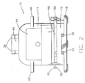
- FIG. 2 is a side elevation view of an HVR according to the invention;
- FIG. 3 is a top view of an HVR according to the invention;
- FIG. 4 is a perspective view of the hardened memory subassembly with the beacon bracket removed;
- FIG. 5 is a perspective view of the mounting base subassembly;
- FIG. 6 is a side elevation view of the hardened memory subassembly with the beacon bracket removed;
- FIG. 7 is a sectional view taken along line A-A in FIG. 6;
- FIG. 8 is a sectional detail of the encircled area of FIG. 2;
- FIG. 9 is a side elevation view of the mounting base subassembly;
- FIG. 10 is a sectional view taken along line B-B of FIG. 9;
- FIG. 11 is a plan view of the mounting base subassembly;
- FIG. 11a is a perspective view of a stacked memory boards including memory interface converter chips;
- FIG. 12 is a sample "screen shot" of the HVR "home page";
- FIG. 13 is a sample screen shot of the HVR login page;
- FIG. 14 is a sample screen shot of the HVR network setup page; and
- FIG. 15 is a sample screen shot of the HVR device update page.
-
- Turning now to Figures 1-3, the Hardened Voyage Recorder (HVR) 10 according to the invention includes two separable subassemblies. The
first subassembly 12 is a mounting base subassembly designed to be directly fastened to the ship and provide a watertight cable entry for power and data connections. Thesecond subassembly 14 is a removable hardened memory subassembly which is attached to the mounting base with a quick releasing clamp. - Referring now to the mechanical features of the
subassembly 12, as shown in Figures 1-3, the mountingbase subassembly 12 has alower flange 16 defining three mountingholes cable connectors subassembly 12 is also provided with anlower flange 28 which is used to provide a sealing engagement with the removablehardened memory subassembly 14. As seen best in Figure 8, theupper flange 28 is provided with twoconcentric grooves gasket 34 and o-ring 36. 36 is preferably a rubber o-ring for moisture protection. 34 is preferably a wire mesh for EMI protection. - The mechanical features of the
hardened memory subassembly 14 include abracket 38 for an externally mountedunderwater location beacon 40. The beacon is preferably provided with dual activation moisture sensors to avoid inadvertent activation due to spray, rain, or hosing off. Thesubassembly 14 also has two lifting handles 42, 44 and anupper flange 46 which is used to provide a sealing engagement with thesubassembly 12 as seen best in Figures 2 and 8. - As shown in Figure 1, the HVR also includes a V-
band 48 having two quick release clamps 50, 52. As mentioned above, the HVR is preferably painted a highly visible florescent orange with white reflective labels,e.g. label 54 shown in Figures 1 and 2. The reflective labels contain the required (by IEC 61996) text: VOYAGE DATA RECORDER, DO NOT OPEN, REPORT TO AUTHORITIES. A strip of reflective tape, 19, is shown in FIG. 1, further satisfying the requirements of IEC 61996. - The presently preferred embodiment of the
HVR 10 is approximately thirteen inches high and has a diameter of approximately eight inches. Thelower flange 16 of thesubassembly 12 is substantially triangular and is approximately ten inches per side. The total weight of the HVR is approximately forty one pounds with the base 12 weighing approximately thirteen pounds and thememory subassembly 14 weighing approximately twenty eight pounds. - Before turning to the electronic and software specifications of the
subassembly 12, it should be noted that thesubassembly 14 includesmemory 56 which is protected in a "boiler" 58 such as that disclosed in previously incorporated application serial number --/---,---. - According to the presently preferred embodiment, electronic access to the
memory 56 is provided by aribbon cable 60 having a (preferably J10)connector 62. The memory is preferably a stacked memory such as that disclosed in previously incorporated application serial number --/---,--- or in U.S. Patent Number 5,969,953, the complete disclosure of which is incorporated by reference herein. More particularly, the memory is preferably of the type utilizing "BGA" packaging (ball grid array packages) as memory components. - Referring now to Figures 5 and 9-11, the mounting
base subassembly 12 includes electronics (partially shown as 64 and 66 in Figures 9 and 10) for receiving data and writing data to the memory in thehardened memory subassembly 14. - According to the presently preferred embodiment, the power connection is provided by a
terminal strip 68 which accepts either 110/220 VAC or 24 VDC or both. The data connection is an ETHERNET connection which is provided by either an RJ-45connector 70 or an optionalETHERNET terminal block 72. The AC and DC power connections may both be active at the same time. The AC connection is preferably used during normal conditions and the DC connection is preferably coupled to the ship's UPS (uninterrupted power supply). The maximum power consumption is preferably fifteen watts. - According to the presently preferred embodiment, the stepped down and bridge rectified AC feeds the same storage capacitor that is fed through a diode by the DC, so the higher voltage at the anodes will provide the operating current. IEC 61996 paragraph 4.5.3 requires a two hour reserve uninterrupted power source (UPS).
- When connecting the ship's UPS system to the HVR, either the AC or DC input may be used. Clearly the negative terminal of the capacitor and the primary side of the switching power supply are grounded to the DC return. If AC is the only power wired, a 1K Ohm resistor ties this input ground to the AC safety ground. The primaries of the AC input transformer can be strapped in parallel for 115 Vrms or in series for 230 Vrms by means of jumpers on the terminal board (not shown).
- The memory is operated by the DC power from the secondary of the switching transformer, and is isolated from the AC and DC power lines. A secondary ground, which is connected to the case and the ETHERNET shield, must be tied to the hull to prevent voltage difference that could induce corrosion. As shown in FIG. 11, according to a preferred embodiment of the invention, a
ground pad 74 is used for grounding. Anotch 76 in theupper flange 28 of thesubassembly 12 is used to prevent pressure differential in a deep sea pressure environment. - Those skilled in the art will appreciate that the ETHERNET cabling should be shielded to protect it from the expected intense RF fields generated by other shipboard equipment such as radar. The foil shield should end as close as possible to the case after it has passed through the sealing
connector 26. The shield's drain wire connects to theground pad 74 which is located about one inch from theconnector 26. Keeping the shield as short as possible inside the case prevents it from re-radiating externally induced signals by using the case as a voltage node. The drain wire at the other end of the ETHERNET cable (at the DMU) should also be grounded to the ship's hull. - As mentioned above, according to the presently preferred embodiment, the memory used in the
subassembly 14 is BGA memory. Accordingly, the circuits in thesubassembly 14 include one or more MICs (memory interface converter chips) needed to interface (convert between) parallel communications which BGA chips employ and the serial communications path with processor. The MICs need to be able to drive the large number of BGA chips distributed in the preferred stacked memory. The MICs may be located on thecircuit board 1101 shown in Figure 11a (MIC chips 1102 and 1103) and/or may be distributed among the memory circuit boards shown in Figure 11a. The processor communicates with the MICs to address memory and the MICs determine which board or stack contains the addressed memory. - Further, as mentioned above, according to the presently preferred embodiment, the HVR receives data via TCP/IP (terminal connection protocol/internet protocol) over ETHERNET. The HVR is therefore assigned an IP address and is configurable via a "web browser". This also enables the formation of a network of multiple HVRs all coupled to numerous sensors via the ETHERNET network.
- Figures 12-15 illustrate a sample interface to the HVR accessible with any web browser coupled to the ETHERNET network to which the HVR is coupled. Those skilled in the art will appreciate that the ship's ETHERNET network could be connected to the Internet via a satellite link, thus making the HVR available from anywhere in the world.
- Figure 12 shows a sample HVR homepage. The default URL of the homepage is 192.168.0.2 which is preset at the factory but which can be changed as shown in Figure 14. The homepage Main Menu, provides the main entry point to HVR system configuration setup via a web browser and provides the links for the configuration options. In addition links are available that describe the HVR Interface Details, HVR System Maintenance, and HVR System Information.
- The "Network Setup" link shown in Figure 12 links to the web page shown in Figure 14 providing a network hostname and IP address setup data entry form.
- The "Flash Setup" link shown in Figure 12 links to a web page shown in Figure 15 providing a memory partition setup data entry form.
- The "Sys Maintenance" link shown in Figure 12 links to a web page (not shown) listing the existing Flash Memory Setup.
- The "Sys Information" link shown in Figure 12 links to a web page (not shown) providing specific HVR software and IP address information.
- The "Set Password" link shown in Figure 12 links to a web page (not shown) providing a password setup data entry form.
- The "HVR Interface" link shown in Figure 12 links to a web page (not shown) providing HVR system interface information.
- The main menu shown in Figure 12 can be accessed without entering a password, but in order to change any HVR system configurations, a password is required to be entered via the password entry page shown in Figure 13. In particular, a password is required to access the Network Setup, Flash Setup, and Set Password pages. Access to any of these pages times out when idle for 300 seconds (which is configurable as shown in Figure 14) and a password must be re-entered to continue with HVR setup modifications.
- The Login Screen of Figure 13 will appear no matter which system configuration button is selected first.
- The HVR is shipped from the factory with the following default IP settings:
- IP address: 192.168.0.2
- Subnet Mask: 255.255.255.0
- Default Gateway IP: 192.168.0.1
-
- Those skilled in the art will appreciate that these are the default settings commonly used with "web-accessible" devices. The "192.168.x.x" IP address scheme is part of a "reserved" block of addresses intended strictly for networks that are not connected to the Internet. When using addresses of this type, the host computer must be configured to an address in this range in order to "see" the HVR and access the HVR's Web pages.
- By selecting the Network Setup link in Figure 12, the user is taken to the page shown in Figure 13 requiring a password entry. The default password for the HVR is "L3HVR". Upon entering the correct password, the user will be taken to the page shown in Figure 14 where the network parameters can be set as required. Changes made will not take effect until the HVR is powered down and back up. Once the settings have been made, the HVR can be connected to the VDR network where it should respond at the configured IP address.
- Using the page shown in Figure 15, the user can modify or set up the memory areas used for data storage on the HVR. Each of these areas or partitions require that two parameters be specified: the partition size and the partition name. This page shows the number of currently available memory devices as well as the per device size in Kilobytes. The user partitions and allocates the HVR memory data storage from the available device pool. The configuration of the memory areas requires that the user specify the size of each memory partition in device units, expressed as the number of devices to be allocated to that memory area. The partition size is thus the device size multiplied by the number of devices.
- The HVR system internally allocates devices from its internal free pool of devices in order to fill the request. The partition configuration request is processed starting with partition 0 (ZERO) and proceeding to partition 9 (NINE). The partition allocations cannot exceed the number of available devices. Partition allocations are processed until all available devices have been allocated.
- The partition name is required during the actual recording of data into a partition. The partition/stream name is to be used by the client application wishing to establish a data connection to the HVR for the storage of data to a particular partition. The connection set up for a data stream requires the partition name. The VDR must use the same partition (stream) name established during the HVR memory configuration in order to establish communication with that partition (stream).
- Once the HVR has been configured, it appears to the outside world as a smart interface to a "pool" of nonvolatile memory. Application programs running on one or more data acquisition systems coupled to the ship's network can utilize the pre-allocated memory partitions for storage and retrieval purposes. Each stream partition is treated as a virtual storage loop in which new data continuously overwrites the oldest data in the partition. The HVR processor keeps track of the current write location in the virtual loop for each partition and preserves this through power cycles in nonvolatile storage.
- In order to store data in a previously allocated partition, or retrieve data from such a partition, software on the client acquisition system must "open" a TCP/IP Socket Connection to the Data Acquisition Server in the HVR. This Server accepts Socket Connections at Port 5000 of the IP Address assigned to the HVR. Once a connection has been made to the HVR Data Acquisition Server, the acquisition software sends a command which identifies the target partition and the requested operation. The partition is identified by using the name that was specified for the stream during the configuration of the memory pool.
- The partition stream can be opened for read or write access, or to request "write status" information. Once the socket connection has been established, and the appropriate command issued, data is sent or received over the Socket Connection. The HVR Data Acquisition Server will accept simultaneous socket connections from multiple client processes as well as multiple socket connections from a single client process. This automatically results from the Client-Server model of the "Berkely Software Distribution" socket interface that is used by the HVR. There are, however, some limitations imposed by the HVR software itself.
- Specifically, there can be only one active "Write" client connection associated with a particular Stream Partition. The HVR does, however, support simultaneous reading from Partitions while writing. The "status query" is supported on a Stream regardless of whether or not there is an active "Read" or "Write" connection on that partition.
- The application layer above TCP/IP is the functional interface between a client data acquisition subsystem and the HVR. It is assumed that the lower protocol layers ensure error-free and timely delivery of messages in both directions. Furthermore, an ETHERNET HVR interface with TCP/IP layers does not rule out multiple concurrent Users of the HVR. Bandwidth of the storage media and communications channels are, of course, issues which must be considered at the system level.
- All messages sent to the HVR begin with a single byte message length value. This represents the number of bytes (characters) in the remainder of the message. For example, the message for opening a partition named "VDR_Radar" for writing would consist of a byte value of 0x0B (11 characters in the remainder of the message), followed by the ASCII characters: WVDR_Radar, followed by a Null terminator (byte value 0x00). Note that the Partition Name, "VDR_Radar" is a 9--character ASCII sequence which is to be followed by a Null terminator character. Along with the 'W' character (for writing) that precedes the Partition Name, the total length of the message is 11 characters. There should be no additional spaces within the message. The "count" byte can be thought of as a specification of exactly how many more characters will be following in order to complete the message. Since the "count" specification is a single byte, the maximum message length is 255 characters.
- Certain HVR messages can include one or more optional arguments. In all cases the optional arguments follow the Null terminator of the base message string. Each argument is, itself, a Null--terminated ASCII string. Numerical values contained in optional arguments are ASCII decimal strings. An example of an optional argument which includes a decimal value would be one which limits the amount of data to be sent by the HVR in response to the "Read from Stream" command.
- In this case, the added argument might be the string "X25". The 'X' character indicates that this is the "Xfer Count" (transfer count) argument, and the "25" is a two--character ASCII--decimal value which represents 25 Mbytes. The "X25" string represents four additional bytes of the complete command (there must be a Null terminator), and would be so reflected in the message length byte that precedes the base message string. It is essential that the base message string, and each optional argument string be followed by a Null terminator byte. There are some optional arguments that consist of a single ASCII character, and these too must be followed by the Null terminator byte.
- Since the message length byte that precedes a request message tells the HVR exactly how many additional bytes must be consumed from the Socket stream in order to obtain the request, that byte must reflect all of the strings and their associated Null terminators. Otherwise the HVR will not "consume" the entire message before attempting to interpret it.
- The "Write to Stream" command is sent by the acquisition system as the first data on a successfully opened TCP/IP Socket Connection. This command consists of an upper or lower--case 'w', followed by the Stream Name that was specified when the stream partition was allocated, followed by a zero value to terminate the Stream Name string. Note that the command must be preceded by the "count byte" as described above.
- If the HVR processor finds this to be a valid Stream Name, it will reply with a single character response of 'G'. If there is a problem with the attempt to establish the "write" connection, one of several error responses will be sent. Once the acquisition client has received a 'G' response, it can begin to send data on the open socket connection stream.
- Optional arguments for the "Write to Stream" command are: "N", for "No Wrap" mode, and "R" for "Reset Write Indices". Neither option takes any additional parameters.
- The "No Wrap" option causes the HVR to first reset the Write location to the start of the Partition before beginning to store any data, and also to stop writing to the specified Stream when the end of the Partition is reached. This is primarily useful in testing the integrity of a Partition.
- The "Reset Indices" option causes the Write location to be reset to the start of the Partition before beginning to store any data. This does, however, allow writing to "Wrap" when the end of the Partition is reached. This is also intended as a "test" feature.
- The "Read from Stream" command is sent by the acquisition system as the first data on a successfully opened TCP/IP Socket Connection. This command consists of an upper or lower case 'r', followed by the Stream Name that was specified when the stream partition was allocated, followed by a zero value to terminate the Stream Name string. Note that the command must be preceded by the "count byte" as described above.
- If the HVR processor finds this to be a valid Stream Name, it will reply with a single character response of 'G'. If there is a problem with the attempt to establish the "read" connection, one of several error responses will be sent. Once the acquisition client has received a 'G' response, it can begin to read data from the open socket connection stream.
- Optional arguments for the "Read from Stream" command are: "N", for "No Wrap" mode, "O" for specifying an "Offset" in Mbytes at which the Reading should begin, and "X" for specifying the total number of Mbytes to be sent by the HVR.
- The "N" option is the counterpart of the "No Wrap" option that is available on the "Write to Stream" command. This option causes the HVR to begin reading at the top of the Partition, and stop reading when the end of the Partition is reached. This is typically used to verify the content of a partition that was filled, for test purposes, using the "N" option on the "Write to Stream" operation.
- The "O"" and "X" options are similar in that they are both followed by an ASCII-decimal value that represents a number in Mbytes. The "O" option represents a backwards offset, relative to the current Write location, at which the reading of data from the Partition is to begin. This is a positive value expressed in Mbytes.
- For example, an argument of "015" would back up by 15 Mbytes from the current Write location. That is, it would set the Read pointer back at the data that was stored 15 Mbytes ago. There are some constraints associated with this option. For example, if a value is specified which is larger than the Partition storage area, then the Read location remains at the current Write location. Also, if the Partition has not been "filled" since the last time the Write location was reset, then the offset will not be adjusted backwards beyond the top of the Partition. This is because data which "follows" the current Write location is meaningless.
- The "Status Query on Stream" command is sent by the acquisition system as the first data on a successfully opened TCP/IP Socket Connection. This command consists of an upper or lower case 's', followed by the Stream Name that was specified when the stream partition was allocated, followed by a zero value to terminate the Stream Name string. Note that the command must be preceded by the "count byte" as described above.
- If the HVR processor finds this to be a valid Stream Name, it will reply with a single character response of 'G'. If there is a problem with the attempt to establish the "status query" connection, one of several error responses will be sent. If the 'G' response is received, it will be followed by a "Status Response" message which conforms to the message format described for commands to the HVR. That is, the remainder of the response will consist of a "count byte" followed by a Null terminated string. The string will be of the form: ''L:n T:n".
- Note that the quotes are NOT part of the response, but are shown to emphasize that the entire response is an ASCII, Null terminated string. The letter 'n' indicates an ASCII decimal representation of the appropriate error count. The first 'n' value is the "Loop Error Count" and represents the number of write errors that occurred on the current pass through the Stream Partition.
- This value is cleared automatically at the start of each pass through the Partition's memory loop. The second 'n' represents the "Total Error Count", and is the accumulated number of errors since the counters were last cleared (manually or as a result of setting up the Partition Map).
- The response to the 'W', 'R', or 'S' commands is a single ASCII character. There is no "count byte" or Null terminator.
- If the Partition Name is valid and access has been established, the response is a 'G' character. If the Partition Name is not recognized, the response is an 'S' character. If the Partition has no devices allocated to it, the response is an 'E' character. If the Partition is busy (another client is already writing in the Partition), the response is a 'B' character. If the Partition is Out of Service for some other reason (failed devices, etc.), the response is an 'O' character.
- Note that the response to the 'S' command is somewhat unique in that it follows the "single ASCII character" form, but if a valid request was made, continues with a "full message" type of response.
- The HVR allows only one Client to be writing to a particular Partition at a time. That is, only one 'W' connection will be allowed for each in-service Partition. The HVR will also accept one or more 'R' connections for a Partition, even if there is currently an active 'W' connection. Issues related to the effects of multiple connections on performance (system throughput) must be carefully considered.
- The response to a 'W' command, for a Partition that already has an active 'W' connection, is the 'B' message (busy).
- The current implementation of the HVR subsystem is capable of data transfer to or from the protected memory store at a rate of around 1.5 Mbits per second (using 10-Base T ETHERNET). That is, a data acquisition host or hosts can send data to the protected memory store, or retrieve data from the store, at approximately this rate, when all other conditions are optimal.
- When sending data to the HVR, the maximum rate can only be achieved if at least three partitions are being written to concurrently. This is a consequence of the architecture of the memory devices being used in the protected memory store and the HVR software that manages the devices. That is, the maximum write rate relies on the HVR software being able to continuously manage concurrent writes in multiple devices.
- There are essentially two buffers used to process the data. The first is the receipt of data packets into an incoming queue, the throughput of this process is approximately 1.5 Mbits per second. The second is in the processing of those data packets from the incoming queue to the flash devices, the throughput of this process is dependent on how the flash chips are managed/mapped. A write to a flash device is slow, relatively speaking, and the software must wait for a write to complete on a given chip before another write can begin. Therefore, if there is only one partition, the writes are all sequential and the throughput will slow to the rate of the chip write function (which can be chip and temperature dependent).
- If however, there are multiple partitions, concurrent writes can occur because the software will be writing to different chips. This effectively increases the throughput by n times, where n is defined by the number of partitions. Since the throughput of the process to receive incoming data packets is approximately 1.5 Mbits per second, the goal of the host computer is to partition the flash devices so that this rate can be achieved. Experimentation has shown at least three to four partitions are required.
- The maximum read rate is also around 1.5 Mbits per second, assuming that there is no simultaneous writing. The rate of a chip read function is much faster than the write so even if there is only one read occurring (sequential access to a chip) it can keep up with the rate of the process to receive incoming data packets.
- When reading and writing are performed together, the available bandwidth of the HVR will be distributed between the operations in a manner that will vary depending on system dynamics.
- There have been described and illustrated herein a hardened voyage data recorder and an example of software for using the recorder over an ETHERNET network. While particular embodiments of the invention have been described, it is not intended that the invention be limited thereto, as it is intended that the invention be as broad in scope as the art will allow and that the specification be read likewise. In particular, the specific arrangement of web pages and the specific communications protocol described herein represent a presently preferred embodiment, but the invention is not limited thereto.
- It will therefore be appreciated by those skilled in the art that yet other modifications could be made to the provided invention without deviating from its spirit and scope as so claimed.
Claims (21)
- A hardened voyage data recorder, comprising:(a) a mounting base subsystem; and(b) a removable memory subsystem removably coupled to said mounting base subsystem.
- A hardened voyage data recorder according to claim 1 further comprising electronic circuits for electronically accessing said memory subsystem, wherein said electronic circuits provide an ETHERNET access port for coupling said hardened voyage recorder to an ETHERNET network.
- A hardened voyage data recorder according to claim 2 wherein said electronic circuits include firmware which provides TCP/IP access over ETHERNET to said circuits.
- A hardened voyage data recorder according to claim 3 wherein said firmware includes web pages for configuring said hardened voyage data recorder.
- A hardened voyage data recorder according to claim 2 wherein said electronic circuits are located in said mounting base subsystem.
- A hardened voyage data recorder according to claim 2 wherein said mounting base subsystem includes at least one watertight cable connector.
- A hardened voyage data recorder according to claim 2 wherein said mounting base subsystem includes a first watertight cable connector for coupling with a power supply and a second cable connector for coupling with an ETHERNET network.
- A hardened voyage data recorder according to claim 2 wherein said electronic circuits accept both 110/220 VAC and 24 VDC power supplies.
- A hardened voyage data recorder according to claim 1 further comprising a quick release V-clamp, wherein said removable memory subsystem has a lower flange, said mounting base subsystem has an upper flange, and said quick release V-claim engages said upper flange and said lower flange whereby said memory subsystem and said base subsystem are removably coupled to each other.
- A hardened voyage data recorder according to claim 9 wherein said quick release V-clamp has two quick release levers.
- A hardened voyage data recorder according to claim 1 wherein said removable memory subsystem includes non-volatile memory enclosed within a boiler.
- A hardened voyage data recorder according to claim 11 wherein said mounting base subsystem includes at least one watertight cable connector.
- A hardened voyage data recorder according to claim 12, wherein said mounting base subsystem includes a first watertight cable connector for coupling with a power supply and a second cable connector for coupling with a data source.
- A hardened voyage data recorder according to claim 9 wherein one of said upper flange and said lower flange has a groove adapted to receive an O-ring.
- A hardened voyage data recorder according to claim 9 wherein said upper flange has two concentric grooves, each adapted to receive an O-ring.
- A hardened voyage data recorder according to claim 15 further comprising one O-ring and one mesh gasket, one disposed in one of said two concentric grooves and the other disposed in the other of said two concentric grooves.
- A hardened voyage data recorder according to claim 1 wherein said mounting base subsystem includes non-volatile memory enclosed within a boiler.
- A hardened voyage data recorder according to claim 17 wherein said mounting bases subsystem includes a first watertight cable connector for coupling with a power supply and a second cable connector for coupling with a data source.
- A hardened voyage data recorder according to claim 1 further comprising at least one memory interface converter chip coupled to said removable memory subsystem.
- A hardened voyage data recorder according to claim 1 wherein said removable memory subsystem includes a stacked memory and a plurality of memory interface chips arranged for communication with a processor such that a large number of memory chips may be driven.
- A hardened voyage data recorder according to claim 20 wherein said mounting base subsystem includes a first watertight cable connector for coupling with a power supply and a second cable connector for coupling with a data source.
Priority Applications (1)
| Application Number | Priority Date | Filing Date | Title |
|---|---|---|---|
| CY20101100394T CY1110018T1 (en) | 2001-03-19 | 2010-05-06 | ENHANCED TRAVEL DATA RECORDING DEVICE |
Applications Claiming Priority (4)
| Application Number | Priority Date | Filing Date | Title |
|---|---|---|---|
| US27702901P | 2001-03-19 | 2001-03-19 | |
| US277029P | 2001-03-19 | ||
| US09/899,647 US6706966B2 (en) | 2001-03-19 | 2001-07-06 | Hardened voyage data recorder |
| US899647 | 2001-07-06 |
Publications (3)
| Publication Number | Publication Date |
|---|---|
| EP1244067A2 true EP1244067A2 (en) | 2002-09-25 |
| EP1244067A3 EP1244067A3 (en) | 2004-12-15 |
| EP1244067B1 EP1244067B1 (en) | 2010-03-24 |
Family
ID=26958272
Family Applications (1)
| Application Number | Title | Priority Date | Filing Date |
|---|---|---|---|
| EP01310321A Revoked EP1244067B1 (en) | 2001-03-19 | 2001-12-11 | Hardened voyage data recorder |
Country Status (11)
| Country | Link |
|---|---|
| US (2) | US6706966B2 (en) |
| EP (1) | EP1244067B1 (en) |
| JP (2) | JP3989746B2 (en) |
| KR (2) | KR20020074388A (en) |
| CN (1) | CN1221433C (en) |
| AT (1) | ATE462172T1 (en) |
| CY (1) | CY1110018T1 (en) |
| DE (1) | DE60141624D1 (en) |
| DK (1) | DK1244067T3 (en) |
| ES (1) | ES2342654T3 (en) |
| PT (1) | PT1244067E (en) |
Cited By (3)
| Publication number | Priority date | Publication date | Assignee | Title |
|---|---|---|---|---|
| EP1748394A2 (en) * | 2005-07-28 | 2007-01-31 | The Boeing Company | Automated integration of fault reporting |
| WO2009056238A1 (en) * | 2007-10-30 | 2009-05-07 | Novega Produktonssysteme Gmbh | Location beacon |
| WO2009068255A1 (en) * | 2007-11-26 | 2009-06-04 | Danelec Electronics A/S | A voyage data recorder |
Families Citing this family (38)
| Publication number | Priority date | Publication date | Assignee | Title |
|---|---|---|---|---|
| US6706966B2 (en) * | 2001-03-19 | 2004-03-16 | L-3 Communications Corporation | Hardened voyage data recorder |
| DE102004013874A1 (en) * | 2004-03-20 | 2005-10-06 | Intergraph (Deutschland) Gmbh | Device for generating an electro-magnetically shielded connection |
| US7105741B2 (en) * | 2004-07-16 | 2006-09-12 | Spx Corporation | Vehicle diagnostic device housing assembly and method positioned and retained in vehicle cup holder |
| US7805228B2 (en) * | 2004-08-19 | 2010-09-28 | Spx Corporation | Vehicle diagnostic device |
| US7885739B2 (en) * | 2004-08-19 | 2011-02-08 | Spx Corporation | Open-ended vehicle diagnostic device interface |
| US7430465B2 (en) | 2004-11-17 | 2008-09-30 | Spx Corporation | Open-ended PC host interface for vehicle data recorder |
| US20060184295A1 (en) * | 2005-02-17 | 2006-08-17 | Steve Hawkins | On-board datalogger apparatus and service methods for use with vehicles |
| KR101005864B1 (en) | 2005-09-01 | 2011-01-05 | 현대중공업 주식회사 | PlayBack method and display mode for the navigation data of the voyage data recorder |
| US7847200B2 (en) * | 2006-09-07 | 2010-12-07 | Siemens Industry, Inc. | Devices, systems, and/or methods for electrically coupling a high voltage electric motor |
| US8016022B2 (en) * | 2006-11-27 | 2011-09-13 | Honeywell International Inc. | Systems and methods for passive thermal management using phase change material |
| US9531581B1 (en) * | 2007-12-18 | 2016-12-27 | Amazon Technologies, Inc. | Method and system for identifying and automatically registering domain names |
| FR2926064B1 (en) * | 2008-01-08 | 2010-03-19 | Faiveley Transp Tours | METHOD OF MAKING A PROTECTION OF OBJECTS AND CAISSON OBTAINED BY ITS IMPLEMENTATION |
| US8340855B2 (en) | 2008-04-22 | 2012-12-25 | Spx Corporation | USB isolation for vehicle communication interface |
| US8121752B2 (en) * | 2008-05-08 | 2012-02-21 | L-3 Communications Coporation | Crash survivable memory unit |
| US8165730B2 (en) * | 2008-06-19 | 2012-04-24 | L-3 Communications Corporation | Flight recorder having integral reserve power supply within form factor of enclosure and method therefor |
| US20100063654A1 (en) * | 2008-09-08 | 2010-03-11 | L-3 Communications Corporation | Locator Beacon Disposed Internal to an Enclosure of a Flight Data Recorder and Method Therefor |
| US20100250058A1 (en) * | 2009-03-31 | 2010-09-30 | Joseph Bernard Steffler | Systems and method for protected memory |
| US8493715B1 (en) * | 2009-09-11 | 2013-07-23 | Lockheed Martin Corporation | Automatically ejecting flight data recorder |
| FR2952747B1 (en) * | 2009-11-13 | 2012-01-20 | Architecture Et Conception De Systemes Avances | METHOD AND DEVICE FOR REMOTELY COLLECTING AIRCRAFT OR SHIP RECORDER DATA |
| US8493720B2 (en) * | 2010-03-04 | 2013-07-23 | Jamal Benbrahim | Quick mounting system and media with compatibility and access control |
| US8213164B2 (en) * | 2010-03-04 | 2012-07-03 | Jamal Benbrahim | Quick mounting system and media for video recording |
| US8670879B1 (en) * | 2010-04-21 | 2014-03-11 | Lockheed Martin Corporation | Automatically ejecting flight data recorder |
| KR101210287B1 (en) | 2010-06-21 | 2012-12-10 | 국방과학연구소 | Telemetry data recording unit with a shock resistant double waterproof structure and data storing/restoring method |
| US8747148B2 (en) | 2010-08-03 | 2014-06-10 | Bosch Automotive Service Solutions Llc | Diagnostic tool with recessed connector |
| EP2630330A2 (en) * | 2010-10-22 | 2013-08-28 | National Oilwell Varco, L.P. | Hardened data recording system for drilling rigs and other drilling equipment |
| CN102095445B (en) * | 2010-12-30 | 2012-08-29 | 中国海洋石油总公司 | Seal shell for acquisition and wireless transmission of deepwater information |
| US8618928B2 (en) | 2011-02-04 | 2013-12-31 | L-3 Communications Corporation | System and methods for wireless health monitoring of a locator beacon which aids the detection and location of a vehicle and/or people |
| US8467420B2 (en) | 2011-07-06 | 2013-06-18 | L-3 Communications Corporation | Systems and methods for synchronizing various types of data on a single packet |
| FR3000267B1 (en) * | 2012-12-20 | 2021-04-16 | Airbus Operations Sas | AIRCRAFT FLIGHT DATA RECORDER |
| CN103093515B (en) * | 2012-12-24 | 2015-11-18 | 江苏海兰船舶电气系统科技有限公司 | Release device of marine data unit |
| CN103035045B (en) * | 2012-12-24 | 2015-11-18 | 江苏海兰船舶电气系统科技有限公司 | data protection unit for ship |
| US9596020B2 (en) * | 2014-08-18 | 2017-03-14 | Sunlight Photonics Inc. | Methods for providing distributed airborne wireless communications |
| CN104960629A (en) * | 2015-06-06 | 2015-10-07 | 陈爱华 | Data protecting device |
| CN105573361B (en) * | 2015-12-30 | 2019-01-18 | 浙江海洋学院 | A kind of programmable device peculiar to vessel |
| JP1579511S (en) * | 2016-07-25 | 2017-06-19 | ||
| CN108961469B (en) * | 2018-07-06 | 2020-12-29 | 深圳市仕联达汽车电子有限公司 | Data storage vehicle event data recorder based on thing networking |
| WO2020062204A1 (en) * | 2018-09-30 | 2020-04-02 | 苏州新阳升科技股份有限公司 | Fixed data storage device of onboard data recorder |
| WO2022134389A1 (en) * | 2020-12-25 | 2022-06-30 | 迟丽艳 | Marine vessel emergency navigation position indicating search and rescue and environment monitoring anti-pollution integrated smart platform |
Citations (8)
| Publication number | Priority date | Publication date | Assignee | Title |
|---|---|---|---|---|
| DE3744421A1 (en) * | 1987-12-29 | 1989-07-13 | Artur Hethey | New means of fastening individual components of a pump to give a pump unit |
| US4944401A (en) * | 1989-09-28 | 1990-07-31 | Sundstrand Data Control, Inc. | Crash survivable enclosure for flight recorder |
| GB2242304A (en) * | 1990-03-24 | 1991-09-25 | Broadgate Ltd | Heat-proof casings for electrical equipment |
| FR2736456A1 (en) * | 1995-07-03 | 1997-01-10 | Loukakos Nicolas | Vehicle data capturing, transmitting and storing system - uses specially programmed computer, high density diskette reader and recorder and cassette video reader and recorder |
| EP0790760A1 (en) * | 1996-02-15 | 1997-08-20 | LORAL, Inc. | Stacked memory for flight recorders |
| US6092008A (en) * | 1997-06-13 | 2000-07-18 | Bateman; Wesley H. | Flight event record system |
| US6153720A (en) * | 1998-04-02 | 2000-11-28 | Alliedsignal Inc. | Data and cockpit voice recorder enclosure |
| US6167238A (en) * | 1999-06-25 | 2000-12-26 | Harris Corporation | Wireless-based aircraft data communication system with automatic frequency control |
Family Cites Families (90)
| Publication number | Priority date | Publication date | Assignee | Title |
|---|---|---|---|---|
| US2389786A (en) | 1942-10-06 | 1945-11-27 | Arthur F Hubbard | Method of and apparatus for signaling |
| US2792274A (en) | 1952-10-28 | 1957-05-14 | Charles K Ruddock | Self-charting compass and automatic navigational instrument |
| US2838360A (en) | 1955-02-16 | 1958-06-10 | John V Foster | Simplified crash data recorder |
| US3268907A (en) | 1956-10-09 | 1966-08-23 | Autoplot Ltd | Position plotting apparatus for use in conjunction with radar |
| US3253810A (en) | 1963-11-21 | 1966-05-31 | Penn Charles James | Portable ejectable help-summoning device |
| US3422418A (en) | 1964-09-17 | 1969-01-14 | Gen Dynamics Corp | Non-linear quickened monitor and controller |
| GB1157961A (en) | 1965-07-28 | 1969-07-09 | Epsylon Res & Dev Co Ltd | Magnetic Recording System for Aircraft |
| US3341871A (en) | 1965-10-04 | 1967-09-19 | Universal Oil Prod Co | Flotation gear for the recovery of a submerged craft |
| GB1207330A (en) | 1967-02-03 | 1970-09-30 | Japan Radio Company Ltd | Radar signal recording and reproducing system |
| US3898650A (en) | 1969-04-02 | 1975-08-05 | Us Navy | Tape recording system for radar |
| US3634887A (en) | 1969-07-25 | 1972-01-11 | Us Navy | Radar video recorder system |
| US3685009A (en) | 1970-06-19 | 1972-08-15 | Sperry Rand Corp | Lookout assist device |
| US3662388A (en) | 1970-07-27 | 1972-05-09 | Us Navy | Method and apparatus for recording high range resolution radar data |
| US3717873A (en) | 1970-11-05 | 1973-02-20 | Sperry Rand Corp | Ship's maneuver assessment system |
| US3697987A (en) | 1970-11-12 | 1972-10-10 | Sperry Rand Corp | Collision avoidance system |
| US3725918A (en) | 1970-11-18 | 1973-04-03 | Sperry Rand Corp | Collision avoidance display apparatus for maneuverable craft |
| US3710313A (en) | 1971-01-13 | 1973-01-09 | P Kimball | Emergency warning systems |
| US3725912A (en) | 1971-05-17 | 1973-04-03 | Us Navy | Radar video recording system |
| US3772692A (en) | 1972-01-05 | 1973-11-13 | Sperry Rand Corp | Marine radar-beacon transponder navigation and collision avoidance system |
| US3833934A (en) | 1972-05-09 | 1974-09-03 | Bkr Inc | Radar data recording and replay system |
| GB1430389A (en) | 1972-06-21 | 1976-03-31 | Solartron Electronic Group | Computing apparatus for tracking movinb objects |
| US3889293A (en) | 1973-03-05 | 1975-06-10 | Us Navy | Radar recording and reproducing system with pulse modulation and time division multiplexing |
| US3840874A (en) | 1973-03-16 | 1974-10-08 | G Dawson | Radar recorder & playback system |
| US3930118A (en) | 1973-04-24 | 1975-12-30 | Gen Time Corp | Radar recorder system |
| US3971018A (en) | 1974-06-24 | 1976-07-20 | Sperry Rand Corporation | Marine traffic conflict assessment system |
| US3906370A (en) | 1974-08-28 | 1975-09-16 | Itt | Radio beacon enclosure |
| US4012784A (en) | 1975-11-28 | 1977-03-15 | Minnesota Mining & Manufacturing Company | Voice logging recorder including decks dedicated for both logging and recall operations |
| US4071898A (en) | 1976-06-14 | 1978-01-31 | Sun Shipbuilding & Dry Dock Company | Ship performance analyzer |
| US4081802A (en) | 1977-01-06 | 1978-03-28 | The United States Of America As Represented By The Secretary Of The Navy | Radar and navigation chart overlay video display system |
| US4232391A (en) | 1978-01-19 | 1980-11-04 | Zanutti Hugo A | Vessel location system |
| US4345462A (en) | 1978-01-19 | 1982-08-24 | Zanutti Hugo A | Vessel location system |
| US4313115A (en) | 1978-05-10 | 1982-01-26 | Sperry Limited | Collision avoidance apparatus |
| US4159644A (en) | 1978-05-15 | 1979-07-03 | Svala Carl G | Ship's log and speedometer |
| US4334425A (en) | 1980-04-18 | 1982-06-15 | Crane Harold E | Ship efficiency analyzer |
| US4428052A (en) | 1981-06-09 | 1984-01-24 | Texas Instruments Incorporated | Navigational aid autopilot |
| US4547778A (en) | 1981-06-09 | 1985-10-15 | Texas Instruments Incorporated | Method and apparatus for automatic distress call signal transmission |
| US4446628A (en) | 1982-09-16 | 1984-05-08 | David Shkolnik | Device for determining angle of inclination of ship |
| US4843575A (en) | 1982-10-21 | 1989-06-27 | Crane Harold E | Interactive dynamic real-time management system |
| US4684949A (en) | 1983-01-17 | 1987-08-04 | The United States Of America As Represented By The Secretary Of Transportation | VHF/radar transponder collision avoidance aid |
| US4694119A (en) | 1983-09-07 | 1987-09-15 | Sundstrand Data Control, Inc. | Heat shielded memory unit for an aircraft flight data recorder |
| AU551038B2 (en) | 1983-09-07 | 1986-04-17 | Sundstrand Data Control, Inc. | Heat shielded flight data memory unit |
| JPS6069511A (en) * | 1983-09-08 | 1985-04-20 | Furuno Electric Co Ltd | Track recorder |
| US4646241A (en) | 1984-06-21 | 1987-02-24 | United Technologies Corporation | Solid-state flight data recording system |
| US4682292A (en) | 1984-07-23 | 1987-07-21 | United Technologies Corporation | Fault tolerant flight data recorder |
| US4839656A (en) | 1984-08-16 | 1989-06-13 | Geostar Corporation | Position determination and message transfer system employing satellites and stored terrain map |
| US4729102A (en) | 1984-10-24 | 1988-03-01 | Sundstrand Data Control, Inc. | Aircraft data acquisition and recording system |
| DE3610372A1 (en) | 1985-03-29 | 1986-11-06 | Gerd 3000 Hannover Ihlenfeld | Protection container |
| US5106520A (en) | 1985-11-22 | 1992-04-21 | The University Of Dayton | Dry powder mixes comprising phase change materials |
| JPS62180168A (en) * | 1986-01-31 | 1987-08-07 | Mitsubishi Heavy Ind Ltd | Sealing mechanism for vacuum vessel |
| US4835537A (en) | 1986-07-16 | 1989-05-30 | Manion James H | Telemetry burst collision avoidance system |
| JPS6364595A (en) | 1986-09-04 | 1988-03-23 | Fanuc Ltd | Motor driving circuit using igbt element |
| JPH0347037Y2 (en) * | 1986-10-17 | 1991-10-04 | ||
| JPH01288225A (en) * | 1988-05-16 | 1989-11-20 | Tokyo Electric Co Ltd | Vacuum cleaner |
| US5193046A (en) | 1988-10-17 | 1993-03-09 | Conner Peripherals, Nc. | Information recording apparatus with a liquid bearing |
| JP2515635Y2 (en) * | 1989-07-12 | 1996-10-30 | エヌオーケー株式会社 | Water purifier |
| US4991000A (en) | 1989-08-31 | 1991-02-05 | Bone Robert L | Vertically interconnected integrated circuit chip system |
| US5032896A (en) | 1989-08-31 | 1991-07-16 | Hughes Aircraft Company | 3-D integrated circuit assembly employing discrete chips |
| JPH0810417Y2 (en) * | 1989-09-13 | 1996-03-29 | 株式会社メイスイ | Water purifier |
| US5370814A (en) | 1990-01-09 | 1994-12-06 | The University Of Dayton | Dry powder mixes comprising phase change materials |
| GB2242330B (en) | 1990-03-24 | 1994-06-01 | Broadgate Ltd | Ship's emergency event monitoring systems |
| US5317463A (en) | 1990-09-25 | 1994-05-31 | Conner Peripherals, Inc. | Information recording apparatus with a liquid bearing |
| FR2673065B1 (en) | 1991-02-20 | 1993-05-14 | Telemecanique | METHOD AND DEVICE FOR THERMALLY PROTECTING ELECTRONIC MEANS AND ELECTRONIC LABEL USING THE SAME. |
| JP3106172B2 (en) * | 1991-02-26 | 2000-11-06 | 東京エレクトロン株式会社 | Sealing structure of heat treatment equipment |
| US5150279A (en) | 1991-03-18 | 1992-09-22 | International Business Machines Corporation | High performance computer system with platters and unidirectional storage modules therebetween |
| JPH04320509A (en) | 1991-04-19 | 1992-11-11 | Gurafuiko:Kk | Parallel processor |
| US5123538A (en) | 1991-04-26 | 1992-06-23 | Sundstrand Corporation | Crash protection enclosure for solid state memory devices |
| JPH05139388A (en) * | 1991-11-20 | 1993-06-08 | Mitsubishi Heavy Ind Ltd | Flight recorder emitting device |
| FR2685644B1 (en) | 1991-12-31 | 1994-04-01 | Fabrication Instruments Mesure | MECHANICAL AND THERMAL PROTECTION DEVICE, PARTICULARLY FOR THE PROTECTION OF DATA RECORDERS INSTALLED ON BOARD AIRCRAFT. |
| JP3178484B2 (en) * | 1992-06-17 | 2001-06-18 | 富士ゼロックス株式会社 | Hydroxygallium phthalocyanine crystal for photoelectric conversion material, method for producing the same, and electrophotographic photoreceptor using the same |
| US5285559A (en) * | 1992-09-10 | 1994-02-15 | Sundstrand Corporation | Method and apparatus for isolating electronic boards from shock and thermal environments |
| JP2603175Y2 (en) * | 1993-07-20 | 2000-02-28 | バブコック日立株式会社 | Double seal structure |
| US5390083A (en) | 1993-09-30 | 1995-02-14 | Honeywell Inc. | Apparatus and method for stiffening circuit card assemblies |
| US5667420A (en) * | 1994-01-25 | 1997-09-16 | Tyco Industries, Inc. | Rotating vehicle toy |
| US5452685A (en) | 1994-03-18 | 1995-09-26 | Thomas; Peggy | Dog booties |
| US5499164A (en) | 1994-06-22 | 1996-03-12 | Northrop Grumman Corporation | High impact digital crash data recorder |
| US5750925A (en) | 1994-10-05 | 1998-05-12 | Loral Fairchild Corp. | Flight crash survivable storage unit with boiler for flight recorder memory |
| US5756934A (en) | 1994-10-11 | 1998-05-26 | Loral Fairchild Corp. | Flight crash survivable storage unit with aquarium container for flight recorder memory |
| FR2734405B1 (en) | 1995-05-18 | 1997-07-18 | Aerospatiale | ELECTRONIC DEVICE PROTECTED AGAINST SHOCK BY CAPSULATION |
| GB2302994B (en) | 1995-07-01 | 1999-06-09 | British Aerospace | Thermal and shock resistant data recorder assembly |
| US5676585A (en) * | 1995-07-12 | 1997-10-14 | The Smalltime Toy Company, Inc. | Toy vehicle having a hinged chassis |
| US5586924A (en) * | 1996-01-25 | 1996-12-24 | Wen Ho Tsai | Toy car structure |
| JPH10259875A (en) * | 1997-03-21 | 1998-09-29 | Hitachi Zosen Corp | Double seal gasket |
| AU7359398A (en) | 1997-04-17 | 1998-11-11 | Stage Iii Technologies, L.C. | Vehicle crash data recorder, locator and communicator |
| JP3251528B2 (en) * | 1997-04-22 | 2002-01-28 | アロン化成株式会社 | Plastic container with lid clamp device |
| DE1077076T1 (en) * | 1998-04-23 | 2001-07-19 | Nikko Kk | TRAVEL TOYS |
| EP1017188A3 (en) | 1998-12-30 | 2001-12-12 | Lucent Technologies Inc. | Method and system for high speed data access from remote locations |
| KR20000065443A (en) * | 1999-04-03 | 2000-11-15 | 조용범 | Black-box for vehicle and interpretation system thereof |
| KR20010002160A (en) * | 1999-06-11 | 2001-01-05 | 오재철 | Device For Shielding Of Memory System In Vehicles And Method For Thereof |
| CN2377522Y (en) | 1999-07-16 | 2000-05-10 | 黄种苇 | Ship's navigation data recorder |
| US6706966B2 (en) * | 2001-03-19 | 2004-03-16 | L-3 Communications Corporation | Hardened voyage data recorder |
-
2001
- 2001-07-06 US US09/899,647 patent/US6706966B2/en not_active Expired - Lifetime
- 2001-12-11 PT PT01310321T patent/PT1244067E/en unknown
- 2001-12-11 DE DE60141624T patent/DE60141624D1/en not_active Expired - Lifetime
- 2001-12-11 ES ES01310321T patent/ES2342654T3/en not_active Expired - Lifetime
- 2001-12-11 DK DK01310321.3T patent/DK1244067T3/en active
- 2001-12-11 AT AT01310321T patent/ATE462172T1/en not_active IP Right Cessation
- 2001-12-11 EP EP01310321A patent/EP1244067B1/en not_active Revoked
-
2002
- 2002-02-07 JP JP2002031519A patent/JP3989746B2/en not_active Expired - Lifetime
- 2002-02-28 KR KR1020020011061A patent/KR20020074388A/en not_active Application Discontinuation
- 2002-03-08 CN CNB021069360A patent/CN1221433C/en not_active Expired - Fee Related
-
2003
- 2003-09-24 US US10/669,385 patent/US7208685B2/en not_active Expired - Lifetime
-
2006
- 2006-02-01 JP JP2006024990A patent/JP4523920B2/en not_active Expired - Lifetime
-
2008
- 2008-09-24 KR KR1020080093896A patent/KR100901200B1/en active IP Right Grant
-
2010
- 2010-05-06 CY CY20101100394T patent/CY1110018T1/en unknown
Patent Citations (8)
| Publication number | Priority date | Publication date | Assignee | Title |
|---|---|---|---|---|
| DE3744421A1 (en) * | 1987-12-29 | 1989-07-13 | Artur Hethey | New means of fastening individual components of a pump to give a pump unit |
| US4944401A (en) * | 1989-09-28 | 1990-07-31 | Sundstrand Data Control, Inc. | Crash survivable enclosure for flight recorder |
| GB2242304A (en) * | 1990-03-24 | 1991-09-25 | Broadgate Ltd | Heat-proof casings for electrical equipment |
| FR2736456A1 (en) * | 1995-07-03 | 1997-01-10 | Loukakos Nicolas | Vehicle data capturing, transmitting and storing system - uses specially programmed computer, high density diskette reader and recorder and cassette video reader and recorder |
| EP0790760A1 (en) * | 1996-02-15 | 1997-08-20 | LORAL, Inc. | Stacked memory for flight recorders |
| US6092008A (en) * | 1997-06-13 | 2000-07-18 | Bateman; Wesley H. | Flight event record system |
| US6153720A (en) * | 1998-04-02 | 2000-11-28 | Alliedsignal Inc. | Data and cockpit voice recorder enclosure |
| US6167238A (en) * | 1999-06-25 | 2000-12-26 | Harris Corporation | Wireless-based aircraft data communication system with automatic frequency control |
Cited By (4)
| Publication number | Priority date | Publication date | Assignee | Title |
|---|---|---|---|---|
| EP1748394A2 (en) * | 2005-07-28 | 2007-01-31 | The Boeing Company | Automated integration of fault reporting |
| EP1748394A3 (en) * | 2005-07-28 | 2007-06-27 | The Boeing Company | Automated integration of fault reporting |
| WO2009056238A1 (en) * | 2007-10-30 | 2009-05-07 | Novega Produktonssysteme Gmbh | Location beacon |
| WO2009068255A1 (en) * | 2007-11-26 | 2009-06-04 | Danelec Electronics A/S | A voyage data recorder |
Also Published As
| Publication number | Publication date |
|---|---|
| US6706966B2 (en) | 2004-03-16 |
| JP4523920B2 (en) | 2010-08-11 |
| CY1110018T1 (en) | 2015-01-14 |
| CN1400137A (en) | 2003-03-05 |
| KR20020074388A (en) | 2002-09-30 |
| KR100901200B1 (en) | 2009-06-08 |
| KR20080093950A (en) | 2008-10-22 |
| ATE462172T1 (en) | 2010-04-15 |
| EP1244067B1 (en) | 2010-03-24 |
| JP2006151385A (en) | 2006-06-15 |
| ES2342654T3 (en) | 2010-07-12 |
| JP3989746B2 (en) | 2007-10-10 |
| US20020129956A1 (en) | 2002-09-19 |
| DE60141624D1 (en) | 2010-05-06 |
| US20040065461A1 (en) | 2004-04-08 |
| JP2002293290A (en) | 2002-10-09 |
| PT1244067E (en) | 2010-05-21 |
| CN1221433C (en) | 2005-10-05 |
| US7208685B2 (en) | 2007-04-24 |
| DK1244067T3 (en) | 2010-06-07 |
| EP1244067A3 (en) | 2004-12-15 |
Similar Documents
| Publication | Publication Date | Title |
|---|---|---|
| US7208685B2 (en) | Hardened voyage data recorder | |
| US5948025A (en) | Vehicle communication control apparatus | |
| US6397128B1 (en) | Flight data recorder system | |
| JP2001145279A5 (en) | ||
| CA2361796C (en) | Hardened voyage data recorder | |
| US6697763B1 (en) | Measurement module and system for monitoring the status of armored vehicle electronic components | |
| CN113436055A (en) | Miniaturized onboard high-speed image storage and processing system | |
| US20230195671A1 (en) | Storage enclosure and system including the storage enclosure | |
| US7032035B2 (en) | Method and apparatus for improving transmission performance by caching frequently-used packet headers | |
| KR101489759B1 (en) | Method for controlling file transfer protocol using storage apparatus | |
| CN111611181A (en) | HID and CDROM composite USB simulation equipment based on wide area network without BIOS and IPMI support | |
| CN210515154U (en) | Embedded AIS device for small-size boats and ships | |
| US6885897B2 (en) | Module for controlling a drive and method of using the module | |
| KR102569600B1 (en) | Method and apparatus for detecting network intrusion of vessel | |
| CA1243116A (en) | Configuration module for avionics signal processing units | |
| KR100293929B1 (en) | Method for handling cache memory in a exchange system | |
| US4437170A (en) | Method and circuit arrangement for the acceptance and temporary storage of data signals in a switching system | |
| GB2298940A (en) | Data backup/restore devices | |
| JPS6432573A (en) | Facsimile equipment | |
| CN116028997A (en) | Storage controller and control system with same | |
| US20050153577A1 (en) | Electronic system for expandably connecting backplanes of hard disks | |
| CN117354193A (en) | Circuit board and data monitoring system | |
| CN115359637A (en) | Station alarm system | |
| JPS61208989A (en) | Catv terminal equipment | |
| JPH1020967A (en) | Information processing system and its initial setting method |
Legal Events
| Date | Code | Title | Description |
|---|---|---|---|
| PUAI | Public reference made under article 153(3) epc to a published international application that has entered the european phase |
Free format text: ORIGINAL CODE: 0009012 |
|
| AK | Designated contracting states |
Kind code of ref document: A2 Designated state(s): AT BE CH CY DE DK ES FI FR GB GR IE IT LI LU MC NL PT SE TR |
|
| AX | Request for extension of the european patent |
Free format text: AL;LT;LV;MK;RO;SI |
|
| PUAL | Search report despatched |
Free format text: ORIGINAL CODE: 0009013 |
|
| AK | Designated contracting states |
Kind code of ref document: A3 Designated state(s): AT BE CH CY DE DK ES FI FR GB GR IE IT LI LU MC NL PT SE TR |
|
| AX | Request for extension of the european patent |
Extension state: AL LT LV MK RO SI |
|
| 17P | Request for examination filed |
Effective date: 20050615 |
|
| AKX | Designation fees paid |
Designated state(s): AT BE CH CY DE DK ES FI FR GB GR IE IT LI LU MC NL PT SE TR |
|
| 17Q | First examination report despatched |
Effective date: 20060405 |
|
| GRAP | Despatch of communication of intention to grant a patent |
Free format text: ORIGINAL CODE: EPIDOSNIGR1 |
|
| GRAS | Grant fee paid |
Free format text: ORIGINAL CODE: EPIDOSNIGR3 |
|
| GRAA | (expected) grant |
Free format text: ORIGINAL CODE: 0009210 |
|
| AK | Designated contracting states |
Kind code of ref document: B1 Designated state(s): AT BE CH CY DE DK ES FI FR GB GR IE IT LI LU MC NL PT SE TR |
|
| REG | Reference to a national code |
Ref country code: GB Ref legal event code: FG4D |
|
| REG | Reference to a national code |
Ref country code: CH Ref legal event code: EP |
|
| REG | Reference to a national code |
Ref country code: IE Ref legal event code: FG4D |
|
| REF | Corresponds to: |
Ref document number: 60141624 Country of ref document: DE Date of ref document: 20100506 Kind code of ref document: P |
|
| REG | Reference to a national code |
Ref country code: PT Ref legal event code: SC4A Free format text: AVAILABILITY OF NATIONAL TRANSLATION Effective date: 20100512 |
|
| REG | Reference to a national code |
Ref country code: DK Ref legal event code: T3 |
|
| REG | Reference to a national code |
Ref country code: GR Ref legal event code: EP Ref document number: 20100401197 Country of ref document: GR |
|
| REG | Reference to a national code |
Ref country code: NL Ref legal event code: T3 |
|
| REG | Reference to a national code |
Ref country code: ES Ref legal event code: FG2A Ref document number: 2342654 Country of ref document: ES Kind code of ref document: T3 |
|
| REG | Reference to a national code |
Ref country code: SE Ref legal event code: TRGR |
|
| PG25 | Lapsed in a contracting state [announced via postgrant information from national office to epo] |
Ref country code: AT Free format text: LAPSE BECAUSE OF FAILURE TO SUBMIT A TRANSLATION OF THE DESCRIPTION OR TO PAY THE FEE WITHIN THE PRESCRIBED TIME-LIMIT Effective date: 20100324 |
|
| PLBI | Opposition filed |
Free format text: ORIGINAL CODE: 0009260 |
|
| 26 | Opposition filed |
Opponent name: NETWAVE SYSTEMS B.V. Effective date: 20101224 |
|
| PLAX | Notice of opposition and request to file observation + time limit sent |
Free format text: ORIGINAL CODE: EPIDOSNOBS2 |
|
| PLBB | Reply of patent proprietor to notice(s) of opposition received |
Free format text: ORIGINAL CODE: EPIDOSNOBS3 |
|
| REG | Reference to a national code |
Ref country code: CH Ref legal event code: PL |
|
| PG25 | Lapsed in a contracting state [announced via postgrant information from national office to epo] |
Ref country code: CY Free format text: LAPSE BECAUSE OF NON-PAYMENT OF DUE FEES Effective date: 20101211 |
|
| PG25 | Lapsed in a contracting state [announced via postgrant information from national office to epo] |
Ref country code: LI Free format text: LAPSE BECAUSE OF NON-PAYMENT OF DUE FEES Effective date: 20101231 Ref country code: CH Free format text: LAPSE BECAUSE OF NON-PAYMENT OF DUE FEES Effective date: 20101231 |
|
| PG25 | Lapsed in a contracting state [announced via postgrant information from national office to epo] |
Ref country code: LU Free format text: LAPSE BECAUSE OF NON-PAYMENT OF DUE FEES Effective date: 20101211 |
|
| PGFP | Annual fee paid to national office [announced via postgrant information from national office to epo] |
Ref country code: DK Payment date: 20121228 Year of fee payment: 12 Ref country code: IE Payment date: 20121226 Year of fee payment: 12 Ref country code: MC Payment date: 20121120 Year of fee payment: 12 Ref country code: FI Payment date: 20121231 Year of fee payment: 12 |
|
| PGFP | Annual fee paid to national office [announced via postgrant information from national office to epo] |
Ref country code: TR Payment date: 20121127 Year of fee payment: 12 Ref country code: PT Payment date: 20121122 Year of fee payment: 12 Ref country code: IT Payment date: 20121219 Year of fee payment: 12 Ref country code: GR Payment date: 20121228 Year of fee payment: 12 Ref country code: GB Payment date: 20121227 Year of fee payment: 12 |
|
| PGFP | Annual fee paid to national office [announced via postgrant information from national office to epo] |
Ref country code: FR Payment date: 20130110 Year of fee payment: 12 |
|
| PGFP | Annual fee paid to national office [announced via postgrant information from national office to epo] |
Ref country code: ES Payment date: 20121226 Year of fee payment: 12 Ref country code: BE Payment date: 20121227 Year of fee payment: 12 Ref country code: DE Payment date: 20121231 Year of fee payment: 12 Ref country code: SE Payment date: 20130102 Year of fee payment: 12 |
|
| PGFP | Annual fee paid to national office [announced via postgrant information from national office to epo] |
Ref country code: NL Payment date: 20121225 Year of fee payment: 12 Ref country code: CY Payment date: 20121203 Year of fee payment: 12 |
|
| RDAF | Communication despatched that patent is revoked |
Free format text: ORIGINAL CODE: EPIDOSNREV1 |
|
| REG | Reference to a national code |
Ref country code: DE Ref legal event code: R103 Ref document number: 60141624 Country of ref document: DE Ref country code: DE Ref legal event code: R064 Ref document number: 60141624 Country of ref document: DE |
|
| RDAG | Patent revoked |
Free format text: ORIGINAL CODE: 0009271 |
|
| STAA | Information on the status of an ep patent application or granted ep patent |
Free format text: STATUS: PATENT REVOKED |
|
| 27W | Patent revoked |
Effective date: 20130711 |
|
| GBPR | Gb: patent revoked under art. 102 of the ep convention designating the uk as contracting state |
Effective date: 20130711 |
|
| REG | Reference to a national code |
Ref country code: PT Ref legal event code: MP4A Effective date: 20140122 |
|
| REG | Reference to a national code |
Ref country code: DE Ref legal event code: R107 Ref document number: 60141624 Country of ref document: DE Effective date: 20140313 |
|
| REG | Reference to a national code |
Ref country code: SE Ref legal event code: ECNC |