EP1243707A2 - Hand shower - Google Patents
Hand shower Download PDFInfo
- Publication number
- EP1243707A2 EP1243707A2 EP02001781A EP02001781A EP1243707A2 EP 1243707 A2 EP1243707 A2 EP 1243707A2 EP 02001781 A EP02001781 A EP 02001781A EP 02001781 A EP02001781 A EP 02001781A EP 1243707 A2 EP1243707 A2 EP 1243707A2
- Authority
- EP
- European Patent Office
- Prior art keywords
- shower
- water jet
- jet nozzles
- hand shower
- hand
- Prior art date
- Legal status (The legal status is an assumption and is not a legal conclusion. Google has not performed a legal analysis and makes no representation as to the accuracy of the status listed.)
- Granted
Links
Images

Classifications
-
- E—FIXED CONSTRUCTIONS
- E03—WATER SUPPLY; SEWERAGE
- E03C—DOMESTIC PLUMBING INSTALLATIONS FOR FRESH WATER OR WASTE WATER; SINKS
- E03C1/00—Domestic plumbing installations for fresh water or waste water; Sinks
- E03C1/02—Plumbing installations for fresh water
- E03C1/04—Water-basin installations specially adapted to wash-basins or baths
- E03C1/0404—Constructional or functional features of the spout
-
- B—PERFORMING OPERATIONS; TRANSPORTING
- B05—SPRAYING OR ATOMISING IN GENERAL; APPLYING FLUENT MATERIALS TO SURFACES, IN GENERAL
- B05B—SPRAYING APPARATUS; ATOMISING APPARATUS; NOZZLES
- B05B1/00—Nozzles, spray heads or other outlets, with or without auxiliary devices such as valves, heating means
- B05B1/14—Nozzles, spray heads or other outlets, with or without auxiliary devices such as valves, heating means with multiple outlet openings; with strainers in or outside the outlet opening
- B05B1/18—Roses; Shower heads
- B05B1/185—Roses; Shower heads characterised by their outlet element; Mounting arrangements therefor
-
- B—PERFORMING OPERATIONS; TRANSPORTING
- B05—SPRAYING OR ATOMISING IN GENERAL; APPLYING FLUENT MATERIALS TO SURFACES, IN GENERAL
- B05B—SPRAYING APPARATUS; ATOMISING APPARATUS; NOZZLES
- B05B15/00—Details of spraying plant or spraying apparatus not otherwise provided for; Accessories
- B05B15/50—Arrangements for cleaning; Arrangements for preventing deposits, drying-out or blockage; Arrangements for detecting improper discharge caused by the presence of foreign matter
- B05B15/52—Arrangements for cleaning; Arrangements for preventing deposits, drying-out or blockage; Arrangements for detecting improper discharge caused by the presence of foreign matter for removal of clogging particles
- B05B15/528—Arrangements for cleaning; Arrangements for preventing deposits, drying-out or blockage; Arrangements for detecting improper discharge caused by the presence of foreign matter for removal of clogging particles by resilient deformation of the nozzle
-
- B—PERFORMING OPERATIONS; TRANSPORTING
- B05—SPRAYING OR ATOMISING IN GENERAL; APPLYING FLUENT MATERIALS TO SURFACES, IN GENERAL
- B05B—SPRAYING APPARATUS; ATOMISING APPARATUS; NOZZLES
- B05B1/00—Nozzles, spray heads or other outlets, with or without auxiliary devices such as valves, heating means
- B05B1/14—Nozzles, spray heads or other outlets, with or without auxiliary devices such as valves, heating means with multiple outlet openings; with strainers in or outside the outlet opening
- B05B1/20—Arrangements of several outlets along elongated bodies, e.g. perforated pipes or troughs, e.g. spray booms; Outlet elements therefor
Definitions
- the invention relates to a hand shower with a water jet nozzle having tubular shower head, in its cylindrical outer jacket the water jet nozzles open.
- a wide variety of hand showers are known, their shower head Has water jet nozzles.
- the shower head consists of several complicated ones molded parts and requires complex assembly.
- the object of the invention is a hand shower of the type mentioned above to improve that they have little with simple construction and easy assembly Has parts and has a high tightness.
- the outer jacket a larger area is formed by an outer tube made of inflexible material is that has a window-shaped longitudinal recess, of which the shower base made of soft plastic or with water jet nozzles Rubber is filled.
- An inner pipe section with a thickening thus forms the shower base and takes over the water flow and the sealing as an integrated component.
- the thickened shower base is strong enough to bend largely prevented by the water pressure.
- the simple construction requires few parts and is easy to assemble. There is also a high one Tightness and the exterior of the hand shower, especially the shower head particularly elegant.
- the shower base is from one Pipe section is formed from soft plastic or rubber, which in particular lies coaxially within the outer tube and in particular with a thickened Wall area as shower base in the window-shaped longitudinal recess of the Outer tube lies.
- a particularly long guidance of the water within the water jet nozzles and thus well-shaped water jets are achieved when the Water jet nozzles are formed from the material of the shower base and that the outer end portions of the water jet nozzles from bulges of the shower base are formed over the outer surface of the shower base protrude. It is also possible to do this by walking the shower base limescale deposits within the nozzles are removed by hand.
- window-shaped longitudinal recess in each case at least one preliminary and / or Return is on a correspondingly shaped return and / or Projection in the side edge of the shower base fits positively. On the one hand, this ensures a secure hold of the shower base in the shower head created and a deflection of the shower base due to the Water pressure prevented.
- a particularly handy and elegant hand shower is formed when on attached a tubular handle to the outer tube of the shower head is molded in particular, which has the same diameter as that of Has shower head.
- the axis of the handle with the axis of the shower head form an obtuse angle of 120 to 175 degrees.
- the outer tube pass through at the outer end a cap is closed.
- the cap can by an axial pin be held, the other end of a water-carrying inner tube of the Handle is tight.
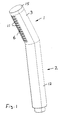
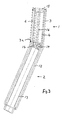
- the hand shower has a shower head 1, at the lower end of which Handle 2 is attached.
- the shower head 1 has an outer tube 3 with a window-shaped rectangular longitudinal recess 3a, which extends over almost the extends the entire length of the tubular shower head 1, the Longitudinal direction is parallel to the axis of the outer tube 3.
- the Outer tube preferably made of a rigid or not soft / flexible Plastic.
- the shower base 6 thus consists of the same soft plastic as that Pipe section 4, the thickness of the wall of the pipe section 4 in the region of shower base is two to three times larger than in the rest of the area.
- the two mutually parallel longitudinal edges 7 of the longitudinal recess 3a have projections 8 which form-fit in recesses 9 of the side walls 10 engage the shower base, so that the shower base 6 and Pipe section 4 are held securely in the outer jacket 5.
- the shower base 6 there are water jet nozzles 11 in rows parallel to the longitudinal axis of the shower head, so that the inside of the pipe section 4 led water can escape from these nozzles to the outside.
- the axes of a series of water jet nozzles lying in one plane the is perpendicular to the pipe axis, oblique to each other and intersect in one Point that lies outside the outer tube 3.
- the water jet nozzles 11 are formed from the material of the shower base 6.
- the outer end portions of the Water jet nozzles 11 are formed by bulges of the shower base 6 protrude beyond the outer surface of the shower base 6.
- an outer tube 12 of the handle is made of molded hard plastic, the axes of both outer tubes 3, 12th with each other an obtuse angle of 120 to 175 degrees, in particular 160 Form degrees.
- the outer and inner diameters of both outer tubes same size.
- a water-carrying inner tube 13 coaxially, on the one a shower hose can be connected at the lower end.
- the top of the Inner tube 13 is closed by a bottom 14 which is a water for Has shower head through bore 17.
- the handle 2 can have a wide variety of shapes and on shower head 1 or on outer tube 3 may also be screwed on.
Abstract
Description
Die Erfindung betrifft eine Handbrause mit einem Wasserstrahldüsen aufweisenden rohrförmigen Brausekopf, in dessen zylindrischen Außenmantel die Wasserstrahldüsen münden.The invention relates to a hand shower with a water jet nozzle having tubular shower head, in its cylindrical outer jacket the water jet nozzles open.
Es sind die verschiedensten Handbrausen bekannt, deren Brausekopf Wasserstrahldüsen aufweist. Der Brausekopf besteht aus mehreren kompliziert geformten Teilen und bedarf einer aufwendigen Montage.A wide variety of hand showers are known, their shower head Has water jet nozzles. The shower head consists of several complicated ones molded parts and requires complex assembly.
Aufgabe der Erfindung ist es, eine Handbrause der eingangs genannten Art so zu verbessern, dass sie bei einfacher Konstruktion und leichter Montage wenig Teile aufweist und eine hohe Dichtigkeit besitzt.The object of the invention is a hand shower of the type mentioned above to improve that they have little with simple construction and easy assembly Has parts and has a high tightness.
Diese Aufgabe wird erfindungsgemäß dadurch gelöst, dass der Außenmantel zu einem größeren Bereich von einem Außenrohr aus unflexiblem Material gebildet ist, das eine fensterförmige Längsausnehmung aufweist, die von dem die Wasserstrahldüsen aufweisenden Brauseboden aus Weichkunststoff oder Gummi ausgefüllt ist. This object is achieved in that the outer jacket a larger area is formed by an outer tube made of inflexible material is that has a window-shaped longitudinal recess, of which the Shower base made of soft plastic or with water jet nozzles Rubber is filled.
Damit bildet ein innerer Rohrabschnitt mit einer Verdickung den Brauseboden und übernimmt als integriertes Bauteil die Wasserführung und die Abdichtung. Hierbei ist der verdickte Brauseboden genügend kräftig, um sein Durchbiegen durch den Wasserdruck weitgehend zu verhindern. Die einfache Konstruktion benötigt wenig Teile und ist leicht zu montieren. Auch besteht eine hohe Dichtigkeit und das Äußere der Handbrause insbesondere des Brausekopfes ist besonders formschön.An inner pipe section with a thickening thus forms the shower base and takes over the water flow and the sealing as an integrated component. The thickened shower base is strong enough to bend largely prevented by the water pressure. The simple construction requires few parts and is easy to assemble. There is also a high one Tightness and the exterior of the hand shower, especially the shower head particularly elegant.
Besonders vorteilhaft ist hierbei, wenn der Brauseboden von einem Rohrabschnitt aus Weichkunststoff oder Gummi gebildet ist, der insbesondere koaxial innerhalb des Außenrohrs liegt und insbesondere mit einem verdickten Wandbereich als Brauseboden in der fensterförmigen Längsausnehmung des Außenrohrs einliegt. Auch kann die Außenfläche des gewölbten Brausebodens, in der die Wasserstrahldüsen münden, teilzylinderförmig sein.It is particularly advantageous here if the shower base is from one Pipe section is formed from soft plastic or rubber, which in particular lies coaxially within the outer tube and in particular with a thickened Wall area as shower base in the window-shaped longitudinal recess of the Outer tube lies. The outer surface of the curved shower base, in which the water jet nozzles open, be partially cylindrical.
Eine besonders lange Führung des Wassers innerhalb der Wasserstrahldüsen und damit gut geformte Wasserstrahlen werden dann erreicht, wenn die Wasserstrahldüsen vom Material des Brausebodens gebildet sind und dass die äußeren Endabschnitte der Wasserstrahldüsen von Aufwölbungen des Brausebodens gebildet sind, die über die Außenfläche des Brausebodens vorstehen. Hierbei ist es auch möglich, dass durch Walken des Brausebodens von Hand Kalkablagerungen innerhalb der Düsen entfernt werden.A particularly long guidance of the water within the water jet nozzles and thus well-shaped water jets are achieved when the Water jet nozzles are formed from the material of the shower base and that the outer end portions of the water jet nozzles from bulges of the Shower base are formed over the outer surface of the shower base protrude. It is also possible to do this by walking the shower base limescale deposits within the nozzles are removed by hand.
Vorzugsweise wird vorgeschlagen, dass in den beiden Längsrändern der fensterförmigen Längsausnehmung jeweils mindestens ein Vor- und/oder Rücksprung ist, der an einem entsprechend geformten Rück- und/oder Vorsprung in dem Seitenrand des Brausebodens formschlüssig anliegt. Hierdurch wird zum einen ein sicherer Halt des Brausebodens im Brausekopf geschaffen und eine Durchbiegung des Brausebodens aufgrund des Wasserdrucks verhindert. It is preferably proposed that in the two longitudinal edges window-shaped longitudinal recess in each case at least one preliminary and / or Return is on a correspondingly shaped return and / or Projection in the side edge of the shower base fits positively. On the one hand, this ensures a secure hold of the shower base in the shower head created and a deflection of the shower base due to the Water pressure prevented.
Besonders vorteilhaft ist es, wenn die Flächen der beiden Längsränder der fensterförmigen Längsausnehmung zueinander parallel sind. Auch ist von Vorteil, wenn die Achsen einer Reihe von Wasserstrahldüsen, die in einer Ebene liegen, zu der die Rohrachse lotrecht ist, in einem Punkt sich schneiden, der außerhalb des Außenrohrs liegt.It when the surfaces of the two longitudinal edges of the window-shaped longitudinal recess are parallel to each other. It is also an advantage if the axes of a series of water jet nozzles lying in one plane to which the pipe axis is perpendicular, intersect at a point that is outside of the outer tube.
Eine besonders handliche und formschöne Handbrause wird gebildet, wenn an dem Außenrohr des Brausekopfes ein rohrförmiger Handgriff befestigt insbesondere angeformt ist, der den selben Durchmesser wie der des Brausekopfes aufweist. Hierbei kann die Achse des Handgriffs mit der Achse des Brausekopfes einen stumpfen Winkel von 120 bis 175 Grad bilden.A particularly handy and elegant hand shower is formed when on attached a tubular handle to the outer tube of the shower head is molded in particular, which has the same diameter as that of Has shower head. Here, the axis of the handle with the axis of the Shower head form an obtuse angle of 120 to 175 degrees.
Vorzugsweise wird vorgeschlagen, dass das Außenrohr am äußeren Ende durch eine Kappe verschlossen ist. Hierbei kann die Kappe durch einen axialen Stift gehalten sein, dessen anderes Ende an einem wasserführenden Innenrohr des Handgriffs fest ist.It is preferably proposed that the outer tube pass through at the outer end a cap is closed. Here, the cap can by an axial pin be held, the other end of a water-carrying inner tube of the Handle is tight.
Ein Ausführungsbeispiel der Erfindung ist in den Zeichnungen dargestellt und wird im folgenden näher beschrieben. Es zeigen
- Fig. 1
- eine isometrische Ansicht der Handbrause,
- Fig. 2
- einen Querschnitt durch den Brausekopf und
- Fig. 3
- einen Längsschnitt durch die Handbrause.
- Fig. 1
- an isometric view of the hand shower,
- Fig. 2
- a cross section through the shower head and
- Fig. 3
- a longitudinal section through the hand shower.
Die Handbrause weist einen Brausekopf 1 auf, an dessen unterem Ende ein
Handgriff 2 befestigt ist. Der Brausekopf 1 besitzt ein Außenrohr 3 mit einer
fensterförmigen rechteckigen Längsausnehmung 3a, die sich über fast die
gesamte Länge des rohrförmigen Brausekopfes 1 erstreckt, wobei deren
Längsrichtung parallel zur Achse des Außenrohrs 3 ist. Hierbei besteht das
Außenrohr vorzugsweise aus einem starren bzw. nicht weichem/flexiblen
Kunststoff.The hand shower has a shower head 1, at the lower end of which
Innerhalb des Außenrohrs 3 liegt ein Rohrabschnitt 4 aus weichem flexiblen
Kunststoff koaxial ein, wobei die Wand des Rohrabschnitts 4 einen verdickten
Bereich aufweist, der die Längsausnehmung 4 ausfüllt und den Außenmantel 5
des Rohres 3 schließt, um den gewölbten Brauseboden 6 zu bilden. Der
Brauseboden 6 besteht somit aus dem selben Weichkunststoff wie der
Rohrabschnitt 4, wobei die Dicke der Wand des Rohrabschnitts 4 im Bereich des
Brausebodens zwei- bis dreimal größer ist als im übrigen Bereich.Inside the
Die beiden zueinander parallelen Längsränder 7 der Längsausnehmung 3a
weisen Vorsprünge 8 auf, die formschlüssig in Rücksprünge 9 der Seitenwände
10 des Brausebodens eingreifen, so dass der Brauseboden 6 und der
Rohrabschnitt 4 sicher im Außenmantel 5 gehalten sind.The two mutually parallel longitudinal edges 7 of the longitudinal recess 3a
have projections 8 which form-fit in
Im Brauseboden 6 sind Wasserstrahldüsen 11 in Reihen parallel zur Längsachse
des Brausekopfes angeordnet, so dass das im Inneren des Rohrabschnitts 4
geführte Wasser aus diesen Düsen nach außen austreten kann. Hierbei stehen
die Achsen einer Reihe von Wasserstrahldüsen, die in einer Ebene liegen, die
rechtwinklig zur Rohrachse ist, zueinander schräg und schneiden sich in einem
Punkt, der außerhalb des Außenrohrs 3 liegt. Die Wasserstrahldüsen 11 sind
vom Material des Brausebodens 6 gebildet. Die äußeren Endabschnitte der
Wasserstrahldüsen 11 sind von Aufwölbungen des Brausebodens 6 gebildet, die
über die Außenfläche des Brausebodens 6 vorstehen.In the
An der Unterseite des Außenrohrs 3 ist ein Außenrohr 12 des Handgriffs aus
hartem Kunststoff angeformt, wobei die Achsen beider Außenrohre 3, 12
miteinander einen stumpfen Winkel von 120 bis 175 Grad insbesondere von 160
Grad bilden. Hierbei sind die Außen- und Innendurchmesser beider Außenrohre
gleich groß. On the underside of the
Im Außenrohr 12 liegt ein wasserführendes Innenrohr 13 koaxial ein, an dessen
unterem Ende ein Brauseschlauch anschließbar ist. Das obere Ende des
Innenrohrs 13 ist durch einen Boden 14 verschlossen, der eine Wasser zum
Brausekopf durchlassende Bohrung 17 aufweist.In the
Das obere Ende des Außenrohrs 3 und des Rohrabschnitts 4 ist durch eine
runde Kappe 15 verschlossen, die in den Rohrabschnitt 4 hineinreicht. Kappe 15
und Boden 14 sind durch einen Stift 16 miteinander verbunden, der den
Rohrabschnitt 4 koaxial durchläuft.The upper end of the
Der Handgriff 2 kann die unterschiedlichsten Formen aufweisen und am
Brausekopf 1 bzw. am Außenrohr 3 auch angeschraubt sein.The
Claims (13)
Applications Claiming Priority (2)
| Application Number | Priority Date | Filing Date | Title |
|---|---|---|---|
| DE10113922A DE10113922A1 (en) | 2001-03-21 | 2001-03-21 | Handheld shower |
| DE10113922 | 2001-03-21 |
Publications (3)
| Publication Number | Publication Date |
|---|---|
| EP1243707A2 true EP1243707A2 (en) | 2002-09-25 |
| EP1243707A3 EP1243707A3 (en) | 2002-12-11 |
| EP1243707B1 EP1243707B1 (en) | 2005-03-16 |
Family
ID=7678495
Family Applications (1)
| Application Number | Title | Priority Date | Filing Date |
|---|---|---|---|
| EP02001781A Expired - Lifetime EP1243707B1 (en) | 2001-03-21 | 2002-01-25 | Hand shower |
Country Status (3)
| Country | Link |
|---|---|
| EP (1) | EP1243707B1 (en) |
| AT (1) | ATE291128T1 (en) |
| DE (2) | DE10113922A1 (en) |
Cited By (2)
| Publication number | Priority date | Publication date | Assignee | Title |
|---|---|---|---|---|
| EP2093333A2 (en) * | 2005-03-04 | 2009-08-26 | Neoperl Gmbh | Sanitary water-outlet fitting with jet regulator for deflecting the exiting water jet |
| CN114433373A (en) * | 2022-03-22 | 2022-05-06 | 珠海格力电器股份有限公司 | Spray pipe structure, range hood and cleaning method |
Families Citing this family (2)
| Publication number | Priority date | Publication date | Assignee | Title |
|---|---|---|---|---|
| US7578453B1 (en) | 2008-02-15 | 2009-08-25 | Kohler Co. | Handshower assembly |
| USD694366S1 (en) | 2011-01-14 | 2013-11-26 | Kohler Co. | Faucet |
Citations (5)
| Publication number | Priority date | Publication date | Assignee | Title |
|---|---|---|---|---|
| DE2901013A1 (en) * | 1979-01-12 | 1980-07-17 | Grohe Kg Hans | Hand held spray head for shower bath - has resilient spray disc clamped inside, forced into curved shape by water pressure |
| DE3044310A1 (en) * | 1980-11-25 | 1982-06-03 | Friedrich Grohe Armaturenfabrik Gmbh & Co, 5870 Hemer | Shower unit for bathrooms - has jets in flexible hose sections, with direction adjusting sleeves |
| GB2279031A (en) * | 1993-06-10 | 1994-12-21 | Stoves Ltd | Manufacture of shower head |
| US5730361A (en) * | 1992-11-04 | 1998-03-24 | Ideal-Standard Gmbh | Shower head with decalcification by deflecting elastic nozzles |
| DE19859315A1 (en) * | 1998-12-22 | 2000-06-29 | Hansgrohe Ag | Shower combination |
Family Cites Families (1)
| Publication number | Priority date | Publication date | Assignee | Title |
|---|---|---|---|---|
| DE2248065C3 (en) * | 1972-09-30 | 1978-03-02 | Kupex Ag, Glarus (Schweiz) | Irrigation device and process for their manufacture |
-
2001
- 2001-03-21 DE DE10113922A patent/DE10113922A1/en not_active Ceased
-
2002
- 2002-01-25 DE DE50202455T patent/DE50202455D1/en not_active Expired - Lifetime
- 2002-01-25 EP EP02001781A patent/EP1243707B1/en not_active Expired - Lifetime
- 2002-01-25 AT AT02001781T patent/ATE291128T1/en not_active IP Right Cessation
Patent Citations (5)
| Publication number | Priority date | Publication date | Assignee | Title |
|---|---|---|---|---|
| DE2901013A1 (en) * | 1979-01-12 | 1980-07-17 | Grohe Kg Hans | Hand held spray head for shower bath - has resilient spray disc clamped inside, forced into curved shape by water pressure |
| DE3044310A1 (en) * | 1980-11-25 | 1982-06-03 | Friedrich Grohe Armaturenfabrik Gmbh & Co, 5870 Hemer | Shower unit for bathrooms - has jets in flexible hose sections, with direction adjusting sleeves |
| US5730361A (en) * | 1992-11-04 | 1998-03-24 | Ideal-Standard Gmbh | Shower head with decalcification by deflecting elastic nozzles |
| GB2279031A (en) * | 1993-06-10 | 1994-12-21 | Stoves Ltd | Manufacture of shower head |
| DE19859315A1 (en) * | 1998-12-22 | 2000-06-29 | Hansgrohe Ag | Shower combination |
Cited By (3)
| Publication number | Priority date | Publication date | Assignee | Title |
|---|---|---|---|---|
| EP2093333A2 (en) * | 2005-03-04 | 2009-08-26 | Neoperl Gmbh | Sanitary water-outlet fitting with jet regulator for deflecting the exiting water jet |
| EP2093333A3 (en) * | 2005-03-04 | 2013-02-20 | Neoperl GmbH | Sanitary water-outlet fitting with jet regulator for deflecting the exiting water jet |
| CN114433373A (en) * | 2022-03-22 | 2022-05-06 | 珠海格力电器股份有限公司 | Spray pipe structure, range hood and cleaning method |
Also Published As
| Publication number | Publication date |
|---|---|
| EP1243707A3 (en) | 2002-12-11 |
| DE10113922A1 (en) | 2002-09-26 |
| EP1243707B1 (en) | 2005-03-16 |
| ATE291128T1 (en) | 2005-04-15 |
| DE50202455D1 (en) | 2005-04-21 |
Similar Documents
| Publication | Publication Date | Title |
|---|---|---|
| DE20118707U1 (en) | Wrench holder | |
| DE3007702A1 (en) | INSPECTION CHAMBER FOR A DRAINAGE SYSTEM | |
| DE4133208A1 (en) | CLEANING DEVICE FOR A TUBE | |
| DE20307538U1 (en) | Wasserzuflußsteuervorrichtung | |
| DE1775077B2 (en) | SINGLE MIXING VALVE | |
| DE102004031415A1 (en) | Flexible suction brush for a vacuum cleaner | |
| EP1243707A2 (en) | Hand shower | |
| DE2819623A1 (en) | SHOWER DEVICE | |
| DE202004016374U1 (en) | connecting element | |
| DE1475566A1 (en) | Line coupling for liquid or gaseous media | |
| DE1921769A1 (en) | Ball joint for connecting linkage parts | |
| EP0449194A1 (en) | Latching device with continuous adjustment for telescopically guided tubes | |
| DE2203511A1 (en) | Fluid syringe with a pressurizable fluid container | |
| EP0643177B1 (en) | Urinal | |
| DE102006004797B3 (en) | Lock supports with outer sleeve made up of upper and lower sections and connected with a lock section | |
| EP1217130A1 (en) | Fixing device for parts of sanitary fittings | |
| AT402682B (en) | Nozzle for vacuum cleaner with removable floor nozzle | |
| DE102018133028B4 (en) | cleaning device | |
| DE3546715C2 (en) | Hand shower | |
| DE19857686A1 (en) | Toilet cleaning appliance has movable head fixed to handle by link | |
| WO2020182372A1 (en) | Travel shower | |
| DE3001688C2 (en) | Hand operated liquid sprayer | |
| DE102018104618B4 (en) | Ball joint | |
| DE202021102411U1 (en) | Quick dismantling structure for sprinkler water spray tubes | |
| DE102016120782A1 (en) | Sleeve connection construction for outlet nozzles |
Legal Events
| Date | Code | Title | Description |
|---|---|---|---|
| PUAI | Public reference made under article 153(3) epc to a published international application that has entered the european phase |
Free format text: ORIGINAL CODE: 0009012 |
|
| AK | Designated contracting states |
Kind code of ref document: A2 Designated state(s): AT BE CH CY DE DK ES FI FR GB GR IE IT LI LU MC NL PT SE TR |
|
| AX | Request for extension of the european patent |
Free format text: AL;LT;LV;MK;RO;SI |
|
| PUAL | Search report despatched |
Free format text: ORIGINAL CODE: 0009013 |
|
| AK | Designated contracting states |
Kind code of ref document: A3 Designated state(s): AT BE CH CY DE DK ES FI FR GB GR IE IT LI LU MC NL PT SE TR |
|
| AX | Request for extension of the european patent |
Free format text: AL;LT;LV;MK;RO;SI |
|
| 17P | Request for examination filed |
Effective date: 20030514 |
|
| 17Q | First examination report despatched |
Effective date: 20030701 |
|
| AKX | Designation fees paid |
Designated state(s): AT DE FR GB IT |
|
| GRAP | Despatch of communication of intention to grant a patent |
Free format text: ORIGINAL CODE: EPIDOSNIGR1 |
|
| GRAS | Grant fee paid |
Free format text: ORIGINAL CODE: EPIDOSNIGR3 |
|
| GRAA | (expected) grant |
Free format text: ORIGINAL CODE: 0009210 |
|
| AK | Designated contracting states |
Kind code of ref document: B1 Designated state(s): AT DE FR GB IT |
|
| REG | Reference to a national code |
Ref country code: GB Ref legal event code: FG4D Free format text: NOT ENGLISH |
|
| REG | Reference to a national code |
Ref country code: IE Ref legal event code: FG4D Free format text: GERMAN |
|
| REF | Corresponds to: |
Ref document number: 50202455 Country of ref document: DE Date of ref document: 20050421 Kind code of ref document: P |
|
| GBT | Gb: translation of ep patent filed (gb section 77(6)(a)/1977) |
Effective date: 20050405 |
|
| PLBE | No opposition filed within time limit |
Free format text: ORIGINAL CODE: 0009261 |
|
| STAA | Information on the status of an ep patent application or granted ep patent |
Free format text: STATUS: NO OPPOSITION FILED WITHIN TIME LIMIT |
|
| PG25 | Lapsed in a contracting state [announced via postgrant information from national office to epo] |
Ref country code: AT Free format text: LAPSE BECAUSE OF NON-PAYMENT OF DUE FEES Effective date: 20060125 |
|
| PG25 | Lapsed in a contracting state [announced via postgrant information from national office to epo] |
Ref country code: FR Free format text: LAPSE BECAUSE OF NON-PAYMENT OF DUE FEES Effective date: 20060131 |
|
| ET | Fr: translation filed | ||
| 26N | No opposition filed |
Effective date: 20051219 |
|
| REG | Reference to a national code |
Ref country code: FR Ref legal event code: ST Effective date: 20060929 |
|
| PGFP | Annual fee paid to national office [announced via postgrant information from national office to epo] |
Ref country code: GB Payment date: 20080123 Year of fee payment: 7 |
|
| GBPC | Gb: european patent ceased through non-payment of renewal fee |
Effective date: 20090125 |
|
| PG25 | Lapsed in a contracting state [announced via postgrant information from national office to epo] |
Ref country code: GB Free format text: LAPSE BECAUSE OF NON-PAYMENT OF DUE FEES Effective date: 20090125 |
|
| PGFP | Annual fee paid to national office [announced via postgrant information from national office to epo] |
Ref country code: IT Payment date: 20150129 Year of fee payment: 14 Ref country code: DE Payment date: 20150121 Year of fee payment: 14 |
|
| REG | Reference to a national code |
Ref country code: DE Ref legal event code: R082 Ref document number: 50202455 Country of ref document: DE Representative=s name: TARVENKORN & WICKORD PATENTANWAELTE PARTG MBB, DE |
|
| REG | Reference to a national code |
Ref country code: DE Ref legal event code: R119 Ref document number: 50202455 Country of ref document: DE |
|
| PG25 | Lapsed in a contracting state [announced via postgrant information from national office to epo] |
Ref country code: DE Free format text: LAPSE BECAUSE OF NON-PAYMENT OF DUE FEES Effective date: 20160802 |
|
| PG25 | Lapsed in a contracting state [announced via postgrant information from national office to epo] |
Ref country code: IT Free format text: LAPSE BECAUSE OF NON-PAYMENT OF DUE FEES Effective date: 20160125 |