EP1243551A2 - Reactor for generating moisture - Google Patents
Reactor for generating moisture Download PDFInfo
- Publication number
- EP1243551A2 EP1243551A2 EP02250896A EP02250896A EP1243551A2 EP 1243551 A2 EP1243551 A2 EP 1243551A2 EP 02250896 A EP02250896 A EP 02250896A EP 02250896 A EP02250896 A EP 02250896A EP 1243551 A2 EP1243551 A2 EP 1243551A2
- Authority
- EP
- European Patent Office
- Prior art keywords
- reactor
- moisture
- structural component
- reflector
- gas
- Prior art date
- Legal status (The legal status is an assumption and is not a legal conclusion. Google has not performed a legal analysis and makes no representation as to the accuracy of the status listed.)
- Granted
Links
Images



Classifications
-
- C—CHEMISTRY; METALLURGY
- C01—INORGANIC CHEMISTRY
- C01B—NON-METALLIC ELEMENTS; COMPOUNDS THEREOF; METALLOIDS OR COMPOUNDS THEREOF NOT COVERED BY SUBCLASS C01C
- C01B5/00—Water
-
- H—ELECTRICITY
- H10—SEMICONDUCTOR DEVICES; ELECTRIC SOLID-STATE DEVICES NOT OTHERWISE PROVIDED FOR
- H10P—GENERIC PROCESSES OR APPARATUS FOR THE MANUFACTURE OR TREATMENT OF DEVICES COVERED BY CLASS H10
- H10P14/00—Formation of materials, e.g. in the shape of layers or pillars
- H10P14/20—Formation of materials, e.g. in the shape of layers or pillars of semiconductor materials
-
- B—PERFORMING OPERATIONS; TRANSPORTING
- B01—PHYSICAL OR CHEMICAL PROCESSES OR APPARATUS IN GENERAL
- B01J—CHEMICAL OR PHYSICAL PROCESSES, e.g. CATALYSIS OR COLLOID CHEMISTRY; THEIR RELEVANT APPARATUS
- B01J12/00—Chemical processes in general for reacting gaseous media with gaseous media; Apparatus specially adapted therefor
- B01J12/007—Chemical processes in general for reacting gaseous media with gaseous media; Apparatus specially adapted therefor in the presence of catalytically active bodies, e.g. porous plates
Definitions
- the present invention relates to improvements in and relating to apparatus for generating moisture for use mainly in semiconductor manufacturing units. More specifically, the invention relates to a reactor for generating moisture that can minimize the quantity of unreacted gases in the generated moisture gas by forcibly mixing hydrogen and oxygen, thus increasing the reaction efficiency, and that can be used in a process in which a relatively small quantity of moisture is required.
- the manufacture of semiconductors typically requires a wide range of flow rates of high purity moisture, from tens of sccm to thousands of sccm.
- the flow rate of moisture required differs according to the actual steps in any given manufacturing process.
- the unit "sccm” as used herein means cm 3 /min. in a standard state.
- the inventors conducted intense research into the development of a reactor for generating moisture of a high flow rate type, producing no less than 1,000 sccm, and disclosed the reactor shown in FIG. 6 in unexamined Japanese patent application, published under No. 2000-169110, and the reactor shown in FIG. 7 in unexamined Japanese patent application, published under No. 2000-297907.
- FIG. 6 is a vertical, sectional view of a first example of a high flow rate type reactor for generating moisture.
- the numeral 91 indicates a structural component on an inlet side; 91a, an inner wall of the structural component on the inlet side; 91b, a material gas feed port; 92, a reactor structural component on an outlet side; 92a, an inner wall of the reactor structural component on the outlet side; 92b, a moisture gas take-out port; 93, a reactor shell; 94, an interior space on the inlet side; 95, a reflector; 95a, the periphery of the reflector; 96, a micro-gap formed between the reflector 95 and the reactor structural component 92 on the outlet side.
- a barrier coat C is formed on the inner wall 91a of the structural component on the inlet side, and a platinum coated catalyst layer D is formed on the inner wall 92a of the reactor structural component on the outlet side.
- Said platinum coated catalyst layer D is made by laminating a platinum coating film on a barrier film of TiN or the like, and the platinum coating film is exposed in the space 96.
- Hydrogen gas and oxygen gas are fed in the direction of the arrow G, and these starting material gases proceed from starting material gas feed port 91b into the interior space 94 on the inlet side. Then, the starting material gases flow in the direction of the arrow H, which forms a stream line, and reach the narrow gap 96 behind the reflector 95.
- the temperature of the whole reactor is adjusted to 350 to 400°C by a heater (not shown) and is set to a temperature for promoting the moisture generating reaction.
- the starting material hydrogen gas and oxygen gas come into contact with the platinum coated catalyst layer D formed on the inner wall 92a of the reactor structural component 92 on the outlet side and are radicalised.
- the radicalised hydrogen and oxygen are in a state of high reactivity and instantly combine with each other at a temperature lower than the ignition point to produce water vapour without combustion at a high temperature.
- FIG. 7 is a vertical, sectional view of a second prior art example of a reactor for generating moisture of the high flow rate type.
- the numerals 91 to 96, G, C, D, I are the same as in FIG. 6.
- Said reactor for generating moisture of the high flow rate type has a construction such that the reactor of fig. 7 comprises a reflector 99 on the inlet side and a filter 100.
- Reflector 99 on the inlet side is formed of casing 99a, reflector 99b on the inlet side and through-hole 99c.
- the filter 100 is made in the form of a stainless steel net which allows fluid to pass through, and is effective in homogenizing the starting material gases diffusing in the interior space 94 on the inlet side and in stabilizing the gases at the same time.
- the starting material gases, homogenized and stabilized after passing through filter 100 therefore proceed into the narrow gap 96 formed behind the reflector 95 and produce moisture gas through the radicalising reaction.
- a disk-like reflector 95 is provided in the interior space, and the starting material gases flow into a narrow gap 96 from the periphery 95a of the reflector. With the radius of reflector 95 as r, the starting material gases are allowed to enter the narrow gap 96 from the entire circumference, represented by 2pr, of the periphery 95a of the reflector. The starting material gases can thus be caused to flow at a high rate into the narrow gap 96, radicalised and then the moisture gas at a high flow rate is fed into a subsequent process.
- the starting material gases form a stream line moderately curved in the direction of the arrow H outside the periphery 95a of the reflector, and the starting material gases therefore proceed substantially in the form of a laminar flow into the narrow gap 96.
- the interaction between gas molecules is relatively weak, Reynold's number reduces, and the flow tends to be in the form of laminar flow.
- the probability of hydrogen and oxygen gas molecule colliding is decreased, and it is thought that the probability of moisture generation will be lower than in the case of turbulent flow.
- the quantity of unreacted gas is therefore constantly monitored, and, if the concentration of unreacted gases exceeds a predetermined level, emergency measures, such as suspension of supply of the starting material gases, are taken.
- the inventors have taken various measures to improve the reaction rate in the prior art reactor. For example, the inventors have improved the platinum coated catalyst layer, made the interior temperature even and uniform throughout the whole reactor and adjusted the ratio between hydrogen gas and oxygen gas in the starting material gases. However, such measures had only a limited effect in improving the reaction ratio. Furthermore, the prior art reactors are reactors for generating moisture at a high flow rate, and the whole volume of the reactor is large. It is some time before moisture gas can be generated and hence the reactor cannot respond promptly when moisture is needed immediately. Another problem is that when moisture gas is no longer needed, it is difficult to replace quickly the moisture gas with inert gas.
- the inventors have come up with a quite different idea to improve the efficiency of the moisture generation reaction.
- the idea is to stir forcibly the starting material gases into a turbulent state in the reactor. Stirring the starting material gases into a turbulent state would sharply increase the collision probability of hydrogen gas and oxygen gas, and, as a result, moisture generation will be more efficient. If the forced turbulence method were to be adopted in a reactor for generating moisture of a low flow rate type that tends to produce laminar flow, then the moisture generation ratio should especially improve.
- the invention as claimed in claim 1 is a reactor for generating moisture which comprises a reactor structural component on an inlet side which supplies starting material gases to an interior space on said inlet side from a starting material gas feed port, a reactor structural component on an outlet side which transfers generated moisture gas to a moisture gas take-out port from a moisture gas feed passage, a reflector tightly clamped air-tight is between the reactor structural component on the inlet side and the reactor structural component on the outlet side and which has a plurality of blowing holes at predetermined locations for communicating with said interior space on the inlet side, a reactor chamber formed with a narrow gap provided between the reflector and the reactor structural component on the outlet side, a nozzle hole formed in the reactor structural component on the outlet side so that said reaction chamber communicates with the moisture gas feed passage in the reactor structural component on the outlet side and a coating catalyst layer formed on a wall surface of the reaction chamber facing the reflector, wherein when hydrogen and oxygen fed from the starting material gas feed port flow into the reaction chamber through the blowing holes in the reflector, hydrogen and
- the invention as claimed in claim 2 is the reactor for generating moisture as claimed in claim 1 wherein a flange on an inlet side is formed on the end face of the reactor structural component on the inlet side, and a flange on the outlet side is formed on an end face of the reactor structural component on the outlet side, with the periphery of the reflector tightly clamped between the flange on the inlet side and the flange on the outlet side.
- the invention as claimed in claim 3 is the reactor for generating moisture according to claim 1, wherein the reactor structural component on the inlet side and the reactor structural component on the outlet side are made of a reactor structural tube on the inlet side and a reactor structural tube on the outlet side, and the reflector is made of a reflection plate.
- the invention as claimed in claim 4 is the reactor for generating moisture as claimed in claim 1 wherein the coating catalyst layer is formed on a surface of the reflector facing the reaction chamber and/or the surface of the nozzle hole.
- the invention as claimed in claim 5 is the reactor for generating moisture as claimed in claim 1 wherein the coating catalyst layer comprises a coating film laminated and fixed on a barrier film.
- the invention as claimed in claim 6 is the reactor for generating moisture as claimed in claim 5 wherein said coating film is made of platinum, and said barrier film is formed of any one of TiN, TiC, TiCN, TiAIN, Al 2 O 3 , Cr 2 O 3 , SiO 2 , and CrN.
- the invention as claimed in claim 7 is a reactor for generating moisture as claimed in claim 2 or claim 3 wherein the periphery of the reflector is tightly clamped between the flange on the inlet side and the flange on the outlet side by a screw engaging a nut or coupling provided on an outer circumferential surface of the reactor structural component on the inlet side, with a coupling or nut provided on the outer circumferential surface of the reactor structural component on the outlet side.
- the invention as claimed in claim 8 is a reactor for generating moisture as claimed in claim 7, with a bearing placed between the nut and a back-side of the flange on which the nut is provided to facilitate turning of the coupling and the screwed nut.
- FIGS. 1, 2 and 3 show a reactor for generating moisture according to the present invention.
- FIG. 1 is a sectional view of the reactor for generating moisture.
- FIG. 2 is a perspective view of the reflector while FIG. 3 is a sectional view of the essential part explaining the operation.
- the numeral 2 indicates a reactor for moisture generation
- 4 is a reactor structural component on an inlet side; 6, a starting material gas feed pipe; 6a, a starting material gas feed port; 8, an interior space on the inlet side; 10, a flange on the inlet side; 12, a reflector; 12a, a inner end face of the reflector; 12b, an outer end face of the reflector; 14, a periphery; 16, a blowing hole; 18, a reaction chamber; 20, a reactor structural component on the outlet side; 20a, an end surface of the reactor structural component on the outlet side; 21, a coating catalyst layer; 21a, a barrier film; 21b, a coating film; 22, a flange on the outlet side; 22a, a flange inner circumferential surface on the outlet side; 24, a nozzle hole; 26, a diffusion section; 28, a moisture gas feed passage; 30, a moisture gas take-out pipe; 30a, a moisture gas take-out port; 32, a coupling;
- a flange 22 on an outlet side is formed on the periphery of an end surface 20a of a large diameter reactor structural component 20 on the outlet side.
- a nozzle hole 24 is formed in the centre of the end surface 20a of the reactor structural component 20 on the outlet side.
- Said nozzle hole 24 is connected to moisture gas feed passage 28 via a diffusion section 26 of frustoconical shape which flares outwardly towards the passage 28.
- said moisture gas feed passage 28 is connected to a moisture gas take-out port 30a of a moisture gas take-out pipe 30, so that the generated moisture gas can be supplied to a process downstream.
- a reflector 12 is provided between the flange 10 on the inlet side and the flange 22 on the outlet side, and its periphery 14 is held and clamped between the two flanges 10, 22. Clamping the reflector 12 between flanges 10, 22 seals the circumferential region of the reflector 12 and keeps that region air-tight.
- the reflector 12 is disk-shaped, and a plurality of small blowing holes 16 are bored on the inner side of the periphery 14 at specific intervals circumferentially. The blowing holes 16 communicate with the interior space 8 on the inlet side.
- the positions of the blowing holes 16 are not limited to circumferential positions. What is important is merely that gases jetted into the blowing holes 16 undergo a moisture generation reaction before the gases reach the nozzle hole 24.
- the blowing holes 16 may thus be zigzagged in the circumferential direction or arranged in the radial direction. Increasing the length of the passage between the blowing holes 16 and the nozzle hole 24 effectively increases the chances of the reaction occurring. In this embodiment, therefore, the blowing holes 16 are provided at positions close to the circumference.
- a coupling 32 is fitted around an outer circumferential surface of the reactor structure component 20, on the outlet side, such that said coupling 32 comes into contact with the flange 22 on the outlet side.
- a bearing 26 is fitted to the outer circumferential surface of the reactor structural component 4 on the inlet side, such that the bearing 36 comes into contact with said flange 10 on the inlet side.
- Said outer surface also carries a nut 34.
- Said nut 34 and said coupling 32 are screwed to each other to provide a reactor for moisture generation 2 of the low flow rate type which is firmly assembled as a single unit.
- the reflector 12 and said, two flanges 10, 22 are firmly united by mating said nut 34 and said coupling 32, thus guaranteeing the durability of the reactor for moisture generation 2 of the present invention.
- the reactor structural component 4 on the inlet side and the reactor structural component 20 on the outlet side are made of pipe, then the reactor structural pipe on the inlet side and the reactor structural pipe on the outlet side can be assembled to form the reactor for moisture generation 2 by merely turning and tightening said nut 34 and said coupling 32.
- the nut 34 is provided on the outer circumferential surface of the reactor structural component 4 on the inlet side, and coupling 32 is disposed around the outer circumferential surface of the reactor structural component 20 on the outlet side.
- Nut 34 and coupling 32 may be interchanged, with the coupling 32 being provided on the outer circumferential surface of the reactor structural component 4 on the inlet side and the nut 34 being disposed on the outer circumferential surface of the reactor structural component 20 on the outlet side.
- an inner end face 12a of the reflector 12 and the end surface 20a of the reactor structural component on the outlet side of the reactor structural component 20 on the outlet side are spaced by narrow gap d, and oppose one another, forming said reaction chamber 18. That is, the periphery of the inlet side of the reaction chamber 18 communicates with the inlet side of the interior space 8 via the plurality of blowing holes 16, and a central region of the outlet side of reaction chamber 18 communicates with the moisture gas feed passage 28 through the nozzle hole 24.
- the reflector 12 shown in FIG. 2 (A) is used.
- This reflector 12 is provided with eight circumferentially equispaced blowing holes 16.
- the reflector 12 shown in FIG. 2(B) is another example in which four circumferentially equispaced blowing holes 16 are formed. As illustrated, the actual number of holes 16 can be selected.
- the only feed ports are the blowing holes 16, and the feed quantity can be adjusted by selecting the number of blowing holes 16 and the hole diameter.
- the diameter of the blowing hole 16 and the nozzle hole 24 can be freely adjusted. To achieve precise control over the low flow rate of the moisture gas, the diameter should be 0.1 mm to 3 mm, preferably 0.5 mm to 2 mm. If the diameter is set within this range, it is easy to mix the starting material gases uniformly.
- the reactor for moisture generation 2 is made of stainless steel, which has excellent durability, corrosion resistance and heat resistance.
- the reactor structural component 4 on the inlet side, the reactor structural component 20 on the outlet side, the reflector 12, the coupling 32 and the nut 34 are made of stainless steel JIS designation SUS316L.
- a coating catalyst layer 21 is formed on a face of the end surface 20a of the reactor structural component 20 on the outlet side. Also, an inner circumferential surface 22a of the flange 22 on the outlet side is coated with a coating catalyst layer 21. Furthermore, the inner end face 12a of the reflector 12 and the surface of the nozzle hole 24 may be coated with a coating catalyst layer 21 depending on the circumstances. However, the coating catalyst layer 21 on the inner end face 12a of the reflector and on the surface of nozzle hole 24 are not always necessary. As described, the coating catalyst layer 21 is formed on the walls of the reaction chamber 18 to increase the water-generating capacity of the reaction chamber 18.
- Said coating catalyst layers 21 are formed as follows. After a barrier film 21a is formed on the stainless steel, a coating film 21b is formed on the barrier film 21a. Said coating film 21b is formed as the top layer in order to activate the starting material gases.
- the barrier film 21a protects the underlying stainless steel materials from oxidation by the flowing gas and stops diffusion of the oxidizing agents, and resists the peeling of the coating film 21b.
- the coating film 21b has a catalytic action in enhancing the reaction of the starting material gases to generate moisture gas.
- the noble metals Ir, Ru, Rh, Pd, Ag, Pt, Au
- platinum (Pt) as a catalytic metal has excellent in heat resistance, stability and efficiency.
- a platinum coating film is therefore often used as the coating film 21b.
- the coating catalyst layer 21 is called a platinum coating catalytic layer.
- the thickness of the coating film 21b is preferably 0.1 ⁇ m to 3 ⁇ m.
- a coating film 21b with a thickness of about 1 ⁇ m is used.
- the thickness of barrier film 21a is preferably 0.1 ⁇ m to 5 ⁇ m.
- a barrier film 21a of TiN with a thickness of about 2 ⁇ m is used.
- barrier film 21a In forming the barrier film 21a, specific surface areas such as the reactor structural component 4 on the inlet side, reactor structural component 20 on the outlet side and reflector 12 are surface treated to remove any oxide or passive state film naturally formed of various metals on the stainless steel surface. Then, the barrier film 21a of TiN is formed. In the present embodiment, a TiN barrier film 21a about 2 ⁇ m is formed by an ion plating process.
- the barrier film can be used in forming the barrier film.
- the examples include TiC, TiCN, TiAIN, Al 2 O 3 , Cr 2 O 3 , SiO 2 , and CrN. These are non catalytic and are highly resistant to oxidation and reduction.
- the thickness of the barrier film is preferably 0.1 ⁇ m to 5 ⁇ m as mentioned above. If the thickness is not greater than 0.1 ⁇ m, then the barrier is not sufficiently effective. If the thickness exceeds 5 ⁇ m, then it takes a long time to form the barrier film. Furthermore, there a risk that the barrier film will peel when heated owing to a difference in expansion coefficients.
- the coating film 21b is formed thereon.
- a coating film 21b about 1 ⁇ m thick is formed by an ion plating method.
- the coating thickness is preferably 0.1 ⁇ m to 3 ⁇ m. If the thickness is not greater than 0.1 ⁇ m, then the catalytic activity of the film may not last very long. If the thickness is greater than 3 ⁇ m, then the cost of the coating film will be too great. Furthermore, a thickness of greater than 3 ⁇ m would make little difference in catalytic activity and retention period. Furthermore, there is a risk of the film peeling when heated owing to a difference in expansion coefficients.
- the coating film 21b can be formed by an ion plating method, and also by such methods as ion spattering, vacuum vapour deposition, chemical vapour deposition and hot pressing.
- the barrier film 21a is formed of an electric conductive material like TiN, then it is possible to use the electrolytic plating.
- the electrode-less plating methods can be used irrespective of the electrical conductivity of the barrier film 21a.
- the starting material gases or a mixture of hydrogen gas and oxygen gas at a predetermined ratio is fed from the starting material gas feed port 6a.
- the starting material gases flow (in the direction of the arrow a) into the interior space 8 on the inlet side and impinge on an outer end face 12b of the reflector 12.
- the starting material gases diffuse and flow in the direction of the arrow b into the reaction chamber 18 through the blowing holes 16.
- the starting material gases violently collide against the end surface 20a and are stirred forcibly into a turbulent state in reaction chamber 18.
- the turbulent motion is further enhanced, whereby the starting material gases are well mixed.
- reaction chamber 18 Since the wall surfaces (end surface 20a, inner circumferential surface 22a) of reaction chamber 18 comprise the coating catalyst layers 21, the mixed gases in a turbulent state violently contact the coating catalyst layer 21 several times. As a result, hydrogen and oxygen molecules are rapidly radicalised into an activated state. Further, the radicalised hydrogen and oxygen radicals repeatedly hit against each other in a turbulent state and associate upon collision to form water molecules.
- a principle aspect of the present invention consists in forcing the starting material gases into a turbulent state in the reaction chamber 18, thereby increasing the efficiency and speed of the radical reaction between hydrogen and oxygen and the generation of moisture.
- the reaction chamber 18 is provided with a narrow gap d.
- Said narrow gap d has a width of 0.1 mm to 5 mm, preferably 0.5 mm to 3 mm. The width of the gap depends on the quantity of moisture required.
- the concentration of starting material gases remaining unreacted in the moisture gas is minimized. That is, the amounts of hydrogen gas and oxygen gas that are discharged unreacted are minimized, and that greatly improves the safety of moisture gas to be sent to a downstream process.
- the amounts of unreacted gases are constantly monitored for safety, if the amounts of unreacted gas are minimized, then there is no possibility that the supply of starting material gases need be suspended.
- the coating catalyst layer 21 may be formed on the inner end face 12a of the reflector 12 to enhance the radicalising and moisture generation reactions in the reaction chamber 18. Also, the inner surface of the nozzle hole 24, where the gas flow path is narrowed may be provided with a coating catalyst layer 21.
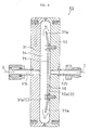
- FIG. 4 is a sectional view of a gas concentration detector 40 of the diaphragm type which is connected to a reactor for generating moisture of the low flow rate type.
- 100% of the starting material gases are reacted to generate moisture gas, with no remaining unreacted gases.
- unreacted gases are always contained in the gases that are discharged.
- the gas concentration detector 40 is used to detect hydrogen gas.
- Said gas concentration detector 40 is designed so that if it is found that the concentration of residual hydrogen gas reaches a specific level, emergency measures such as suspension of the supply of starting material gases will be taken.
- Said gas concentration detector 40 comprises a moisture gas inlet pipe 42, a sensor body 44 comprising a measurement space 46, a supporter 45 and a tightening flange body 52 to clamp tightly the diaphragm detector 50, a tightening bolt 54 and a moisture gas lead pipe 48.
- Generated moisture gas flows from the moisture gas inlet pipe 42 into the measurement space 46 in the direction of arrow e. After the residual hydrogen concentration has been detected by the diaphragm detector 50, the gas is supplied to the a subsequent process in the direction of arrow f, through the moisture gas lead pipe 48.
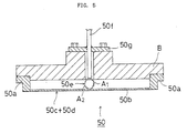
- FIG. 5 is a sectional view of the diaphragm detector 50.
- a thin plate-formed diaphragm 50b surrounded by a diaphragm base 50a is provided and said diaphragm base 50a is fixed to a thermocouple supporter B.
- a through-hole is made in the centre of thermocouple supporter B.
- a sheath body 50f in which a thermocouple 50e is mounted is inserted.
- Said sheath body 50f is fixed to the thermocouple supporter B by means of a collar body 50g.
- thermocouple 50e is made of two kinds of thermocouple metal A1, A2. Among such metals are chromel-alumel, copper-constantan, iron-constantan. One contact point of said thermocouple metals for A1, A2 is fused and spot-welded onto the reverse side of the diaphragm 50b, and another contact point arranged so as to measure the room temperature. In detecting temperature, compensation is made for room temperature.
- a coating catalytic layer is formed on the surface of the diaphragm 50b that contacts the moisture gas, which coating catalyst layer comprises a base, or underlying barrier film 50c and an exposed coating film 50d. If moisture gas impinges on the coating catalytic layer, then small quantities of hydrogen gas and oxygen gas in the moisture gas are radicalised causing a moisture generating reaction. If moisture is generated, then the diaphragm 50b is heated by heat generated by the reaction and temperature rises. This temperature rise is detected by the thermocouple 50e as a measure of the concentration of unreacted gases in moisture gas.
- concentration of hydrogen gas remaining in moisture gas is found to be higher than a predetermined level, an alarm is sounded, and the supply of starting material gases is suspended. If a correction is made to bring down the concentration of unreacted gas to below the predetermined level, then the moisture generation reaction is re-started and generated gas is supplied to the subsequent process.
- the present invention can exhibit the aforesaid effects well if it is applied to reactor for generating moisture of the low flow rate type. However, if the number of blowing holes 16 is increased, then the reactor for generating moisture can be of a high flow rate type. In that case, too, the gas turbulence and mixing are effected sufficiently, and the efficiency of moisture generation can be improved.
- starting material gases are blown into a small gap reaction chamber 18 through a plurality of blowing holes 16 provided at predetermined locations on reflector 12, and therefore the starting material gases are in a turbulent state and evenly mixed, which accelerates the formation of radicals at the coating catalyst layer 21 and enhances the moisture generation reaction at the same time.
- starting material gases are supplied at a low flow rate, moisture can be generated with a high efficiency, whereby residual unreacted gases can be reduced to a minimum. The same results can be obtained with the high flow rate.
- the periphery of the reflector 12 is tightly clamped between the flange 10 on the inlet side and the flange 22 on the outlet side, and therefore reactor structural component 4 on the inlet side and the reactor structural component 20 on the outlet side can be assembled securely and air-tightly, and thus the durability of the whole reactor can be improved.
- the reactor comprises a reactor structural tube on the inlet side and a reactor structural tube on the outlet side such that clamping of the reflector 12 and assembly of the reactor can be achieved by engaging and tightening the coupling 32 and the nut 34 alone.
- the coating catalyst layer 21 is formed on an inner end face 12a of the reflector 12, facing the reaction chamber, and/or the surface of nozzle hole 24, and the radicalising reaction and moisture generation reaction can therefore be carried out with high efficiency, and the concentrations of residual unreacted gases can be reduced to a minimum.
- coating catalyst layer 21 is formed by laminating and fixing a coating film 21b onto a barrier film 21a, and there is therefore no possibility of the coating film 21b peeling off .
- the barrier film 21a also protects the underlying metal from oxidation and there is no diffusion of the base metal into the platinum. Thus, a durable reactor for generating moisture is provided.
- the barrier film 21a comprises any one of TiN, TiC, TiCN, TiAIN, Al 2 O 3 , Cr 2 O 3 , SiO 2 , CrN. These materials improve durability of coating film 21b, and prevent the base metal oxidizing and diffusing. Hence, a reactor for generating moisture with a long-life can be provided.
- the reactor for generating moisture can be assembled by screwing nut 34 and coupling 32 alone, which makes it possible to reduce the costs of manufacturing the reactor for generating moisture.
Landscapes
- Chemical & Material Sciences (AREA)
- Organic Chemistry (AREA)
- Inorganic Chemistry (AREA)
- Chemical Kinetics & Catalysis (AREA)
- Physical Or Chemical Processes And Apparatus (AREA)
- Hydrogen, Water And Hydrids (AREA)
Abstract
Description
Claims (8)
- A reactor (2) for generating moisture comprising:a first inlet-side reactor structural component (4) and a second outlet-side reactor structural component (20), which first and second structural components (4,20) are adapted to be assembled to define an interior space;a starting material gas feed port (6a) in said first structural component, which gas feed port is adapted to supply starting material gases to an inlet side (8) of said interior space;a moisture gas feed passage (28) in said second structural component, adapted to remove generated gas to a moisture gas take-out port (30a); a reflector (12) clamped air-tightly between the first and second reactor structural components (4,20), which reflector defines a plurality of blowing holes (16) at predetermined locations in communication with said inlet-side (8) interior space;a reactor chamber (18) comprising a narrow gap intermediate said reflector (12) and said second reactor structural component (20);a nozzle hole (24) formed in the second reactor structural component (20) such that said reaction chamber communicates with said moisture gas feed passage (28) in the second reactor structural component;and a coating catalyst layer (21) formed on a wall surface of said reaction chamber facing the reflector, wherein when hydrogen and oxygen fed from the starting material gas feed port flow into the reaction chamber through the blowing holes in the reactor, hydrogen and oxygen react and generate moisture gas in a non-combustion state through catalytic effect of the coating catalyst layer.
- A reactor for generating moisture as claimed in claim 1, wherein a first inlet-side flange (10) is formed on an end of the first structural component (4), and a second outlet-side flange (22) is formed on an end the second structural component (20), and the periphery of the reflector (12) is tightly clamped between the first and second flanges (10,22).
- A reactor for generating moisture as claimed in claim 1 or claim 2, wherein the first structural component (4) and the second structural component (20) each comprise a structural tube, and said reflector (12) comprises a reflection plate.
- A reactor for generating moisture as claimed in claim 1, claim 2 or claim 3, wherein a coating catalyst layer (21) is formed on a surface of the reflector (12) facing said reaction chamber (18) and/or an interior surface of the nozzle hole (24).
- A reactor for generating moisture as claimed in any preceding claim, wherein said coating catalyst layer (21) comprises a coating film (21b) laminated and fixed onto a barrier film (21a).
- A reactor for generating moisture as claimed in claim 5, wherein said coating film (21b) comprises platinum, and said barrier film (21a) comprises of any one of TiN, TiC, TiCN, TiAIN, Al2O3, Cr2O3, SiO2, CrN.
- A reactor for generating moisture as claimed in claim 2 or claim 3, wherein the periphery of the reflector (12) is tightly clamped between the first and second flanges (10,22) by means of a screw-threaded nut member (34) provided on the outer circumferential surface of one of the first and second structural components (4,20) and a correspondingly screw-threaded coupling member (32) provided on the outer circumferential surface of the other structural component (20,4), wherein said nut member is adapted to engage said coupling member.
- A reactor for generating moisture as claimed in claim 7, wherein a bearing (36) is interposed between said nut member(34) and a reverse side of the flange (10,22) on which said nut is provided, thereby to facilitate turning of the coupling (32) and the nut (34).
Applications Claiming Priority (2)
| Application Number | Priority Date | Filing Date | Title |
|---|---|---|---|
| JP2001084507A JP2002274812A (en) | 2001-03-23 | 2001-03-23 | Reactor for moisture generation |
| JP2001084507 | 2001-03-23 |
Publications (3)
| Publication Number | Publication Date |
|---|---|
| EP1243551A2 true EP1243551A2 (en) | 2002-09-25 |
| EP1243551A3 EP1243551A3 (en) | 2003-07-02 |
| EP1243551B1 EP1243551B1 (en) | 2004-05-26 |
Family
ID=18940166
Family Applications (1)
| Application Number | Title | Priority Date | Filing Date |
|---|---|---|---|
| EP02250896A Expired - Lifetime EP1243551B1 (en) | 2001-03-23 | 2002-02-08 | Reactor for generating moisture |
Country Status (9)
| Country | Link |
|---|---|
| US (1) | US20020136676A1 (en) |
| EP (1) | EP1243551B1 (en) |
| JP (1) | JP2002274812A (en) |
| KR (1) | KR20020075202A (en) |
| CN (1) | CN1376632A (en) |
| DE (1) | DE60200524T2 (en) |
| IL (1) | IL148236A0 (en) |
| SG (1) | SG102028A1 (en) |
| TW (1) | TW520346B (en) |
Cited By (1)
| Publication number | Priority date | Publication date | Assignee | Title |
|---|---|---|---|---|
| RU2403085C1 (en) * | 2009-04-23 | 2010-11-10 | Государственное образовательное учреждение высшего профессионального образования "Алтайский государственный технический университет им. И.И. Ползунова" (АлтГТУ) | Unltrasound flow reactor |
Families Citing this family (3)
| Publication number | Priority date | Publication date | Assignee | Title |
|---|---|---|---|---|
| WO2001010774A1 (en) * | 1999-08-06 | 2001-02-15 | Fujikin Incorporated | Moisture generating/supplying device and moisture generating reactor |
| ES2952997T3 (en) * | 2018-06-22 | 2023-11-07 | Molecular Plasma Group Sa | Improved method and apparatus for atmospheric pressure plasma jet coating deposition on a substrate |
| KR102454649B1 (en) * | 2018-09-25 | 2022-10-17 | 가부시키가이샤 후지킨 | concentration measuring device |
Family Cites Families (9)
| Publication number | Priority date | Publication date | Assignee | Title |
|---|---|---|---|---|
| EP1911722A2 (en) * | 1996-01-29 | 2008-04-16 | FUJIKIN Inc. | Method for generating moisture, reactor for generating moisture, method for controlling temperature of reactor for generating moisture, and method for forming platinum-coated catalyst layer |
| JP3644790B2 (en) * | 1997-04-28 | 2005-05-11 | 忠弘 大見 | Water generation reactor |
| JP3808975B2 (en) * | 1997-06-17 | 2006-08-16 | 忠弘 大見 | Moisture generation method for semiconductor manufacturing |
| JP3644810B2 (en) * | 1997-12-10 | 2005-05-11 | 株式会社フジキン | Low flow rate water supply method |
| JP3639440B2 (en) * | 1998-09-02 | 2005-04-20 | 忠弘 大見 | Water generation reactor |
| JP3679636B2 (en) * | 1998-12-04 | 2005-08-03 | 株式会社フジキン | Water generation reactor |
| JP3686761B2 (en) * | 1998-12-04 | 2005-08-24 | 株式会社フジキン | Water generation reactor |
| WO2001010774A1 (en) * | 1999-08-06 | 2001-02-15 | Fujikin Incorporated | Moisture generating/supplying device and moisture generating reactor |
| IL144024A0 (en) * | 2000-06-05 | 2002-04-21 | Fujikin Kk | Reactor for generating moisture |
-
2001
- 2001-03-23 JP JP2001084507A patent/JP2002274812A/en active Pending
- 2001-11-22 TW TW090128934A patent/TW520346B/en not_active IP Right Cessation
- 2001-12-26 KR KR1020010085138A patent/KR20020075202A/en not_active Ceased
-
2002
- 2002-02-01 SG SG200200439A patent/SG102028A1/en unknown
- 2002-02-08 DE DE60200524T patent/DE60200524T2/en not_active Expired - Fee Related
- 2002-02-08 EP EP02250896A patent/EP1243551B1/en not_active Expired - Lifetime
- 2002-02-19 IL IL14823602A patent/IL148236A0/en not_active IP Right Cessation
- 2002-03-12 US US10/096,247 patent/US20020136676A1/en not_active Abandoned
- 2002-03-25 CN CN02107862A patent/CN1376632A/en active Pending
Cited By (1)
| Publication number | Priority date | Publication date | Assignee | Title |
|---|---|---|---|---|
| RU2403085C1 (en) * | 2009-04-23 | 2010-11-10 | Государственное образовательное учреждение высшего профессионального образования "Алтайский государственный технический университет им. И.И. Ползунова" (АлтГТУ) | Unltrasound flow reactor |
Also Published As
| Publication number | Publication date |
|---|---|
| EP1243551A3 (en) | 2003-07-02 |
| KR20020075202A (en) | 2002-10-04 |
| EP1243551B1 (en) | 2004-05-26 |
| IL148236A0 (en) | 2002-09-12 |
| SG102028A1 (en) | 2004-02-27 |
| JP2002274812A (en) | 2002-09-25 |
| US20020136676A1 (en) | 2002-09-26 |
| TW520346B (en) | 2003-02-11 |
| CN1376632A (en) | 2002-10-30 |
| DE60200524T2 (en) | 2005-06-23 |
| DE60200524D1 (en) | 2004-07-01 |
Similar Documents
| Publication | Publication Date | Title |
|---|---|---|
| CA2244688C (en) | Method for generating moisture, reactor for generating moisture, method for controlling temperature of reactor for generating moisture, and method for forming platinum-coated catalyst layer | |
| EP1243551B1 (en) | Reactor for generating moisture | |
| US20070231225A1 (en) | Apparatus and reactor for generating and feeding high purity moisture | |
| EP0922667B1 (en) | Method for generating water for semiconductor production | |
| EP0987217B1 (en) | Reactor for generation of moisture | |
| US6919056B2 (en) | Reactor for generating moisture | |
| TW536525B (en) | Unreacted gas detector and unreacted gas sensor | |
| JP2000072405A (en) | Reaction furnace for generating water | |
| JPH10183352A (en) | Evaporator and chemical vapor deposition system | |
| JP3686761B2 (en) | Water generation reactor | |
| JP3679636B2 (en) | Water generation reactor | |
| CN119571293B (en) | Plasma jet nozzle and plasma enhanced chemical vapor deposition equipment | |
| US20240269643A1 (en) | A catalytic reactor and a method for providing a catalytic reaction | |
| TW466213B (en) | Reaction furnace for generating water | |
| IL141729A (en) | Method for generating water for semiconductor production |
Legal Events
| Date | Code | Title | Description |
|---|---|---|---|
| PUAI | Public reference made under article 153(3) epc to a published international application that has entered the european phase |
Free format text: ORIGINAL CODE: 0009012 |
|
| 17P | Request for examination filed |
Effective date: 20020305 |
|
| AK | Designated contracting states |
Kind code of ref document: A2 Designated state(s): AT BE CH CY DE DK ES FI FR GB GR IE IT LI LU MC NL PT SE TR |
|
| AX | Request for extension of the european patent |
Free format text: AL;LT;LV;MK;RO;SI |
|
| PUAL | Search report despatched |
Free format text: ORIGINAL CODE: 0009013 |
|
| AK | Designated contracting states |
Designated state(s): AT BE CH CY DE DK ES FI FR GB GR IE IT LI LU MC NL PT SE TR |
|
| AX | Request for extension of the european patent |
Extension state: AL LT LV MK RO SI |
|
| GRAP | Despatch of communication of intention to grant a patent |
Free format text: ORIGINAL CODE: EPIDOSNIGR1 |
|
| GRAS | Grant fee paid |
Free format text: ORIGINAL CODE: EPIDOSNIGR3 |
|
| AKX | Designation fees paid |
Designated state(s): CH DE FR GB IT LI NL |
|
| GRAA | (expected) grant |
Free format text: ORIGINAL CODE: 0009210 |
|
| AK | Designated contracting states |
Kind code of ref document: B1 Designated state(s): CH DE FR GB IT LI NL |
|
| REG | Reference to a national code |
Ref country code: GB Ref legal event code: FG4D |
|
| REG | Reference to a national code |
Ref country code: CH Ref legal event code: EP |
|
| REG | Reference to a national code |
Ref country code: CH Ref legal event code: NV Representative=s name: E. BLUM & CO. PATENTANWAELTE |
|
| REG | Reference to a national code |
Ref country code: IE Ref legal event code: FG4D |
|
| REF | Corresponds to: |
Ref document number: 60200524 Country of ref document: DE Date of ref document: 20040701 Kind code of ref document: P |
|
| PGFP | Annual fee paid to national office [announced via postgrant information from national office to epo] |
Ref country code: FR Payment date: 20041118 Year of fee payment: 4 |
|
| ET | Fr: translation filed | ||
| PGFP | Annual fee paid to national office [announced via postgrant information from national office to epo] |
Ref country code: DE Payment date: 20050331 Year of fee payment: 4 |
|
| PLBE | No opposition filed within time limit |
Free format text: ORIGINAL CODE: 0009261 |
|
| STAA | Information on the status of an ep patent application or granted ep patent |
Free format text: STATUS: NO OPPOSITION FILED WITHIN TIME LIMIT |
|
| 26N | No opposition filed |
Effective date: 20050301 |
|
| PG25 | Lapsed in a contracting state [announced via postgrant information from national office to epo] |
Ref country code: GB Free format text: LAPSE BECAUSE OF NON-PAYMENT OF DUE FEES Effective date: 20060208 |
|
| PG25 | Lapsed in a contracting state [announced via postgrant information from national office to epo] |
Ref country code: LI Free format text: LAPSE BECAUSE OF NON-PAYMENT OF DUE FEES Effective date: 20060228 Ref country code: CH Free format text: LAPSE BECAUSE OF NON-PAYMENT OF DUE FEES Effective date: 20060228 |
|
| PGFP | Annual fee paid to national office [announced via postgrant information from national office to epo] |
Ref country code: IT Payment date: 20060228 Year of fee payment: 5 |
|
| PG25 | Lapsed in a contracting state [announced via postgrant information from national office to epo] |
Ref country code: NL Free format text: LAPSE BECAUSE OF NON-PAYMENT OF DUE FEES Effective date: 20060901 Ref country code: DE Free format text: LAPSE BECAUSE OF NON-PAYMENT OF DUE FEES Effective date: 20060901 |
|
| REG | Reference to a national code |
Ref country code: CH Ref legal event code: PL |
|
| GBPC | Gb: european patent ceased through non-payment of renewal fee |
Effective date: 20060208 |
|
| NLV4 | Nl: lapsed or anulled due to non-payment of the annual fee |
Effective date: 20060901 |
|
| REG | Reference to a national code |
Ref country code: FR Ref legal event code: ST Effective date: 20061031 |
|
| PG25 | Lapsed in a contracting state [announced via postgrant information from national office to epo] |
Ref country code: FR Free format text: LAPSE BECAUSE OF NON-PAYMENT OF DUE FEES Effective date: 20060228 |
|
| PG25 | Lapsed in a contracting state [announced via postgrant information from national office to epo] |
Ref country code: IT Free format text: LAPSE BECAUSE OF NON-PAYMENT OF DUE FEES Effective date: 20070208 |