EP1243457A2 - Tracking of a target vehicle using adaptive cruise control - Google Patents
Tracking of a target vehicle using adaptive cruise control Download PDFInfo
- Publication number
- EP1243457A2 EP1243457A2 EP02005751A EP02005751A EP1243457A2 EP 1243457 A2 EP1243457 A2 EP 1243457A2 EP 02005751 A EP02005751 A EP 02005751A EP 02005751 A EP02005751 A EP 02005751A EP 1243457 A2 EP1243457 A2 EP 1243457A2
- Authority
- EP
- European Patent Office
- Prior art keywords
- vehicle
- cruise control
- adaptive cruise
- control system
- acc
- Prior art date
- Legal status (The legal status is an assumption and is not a legal conclusion. Google has not performed a legal analysis and makes no representation as to the accuracy of the status listed.)
- Withdrawn
Links
- 230000003044 adaptive effect Effects 0.000 title claims abstract description 24
- 238000012360 testing method Methods 0.000 claims abstract description 35
- 238000012544 monitoring process Methods 0.000 claims abstract description 6
- 230000007423 decrease Effects 0.000 claims description 15
- 208000020990 adrenal cortex carcinoma Diseases 0.000 description 120
- 238000000034 method Methods 0.000 description 3
- 239000013598 vector Substances 0.000 description 3
- 230000003247 decreasing effect Effects 0.000 description 2
- 238000010276 construction Methods 0.000 description 1
- 238000010586 diagram Methods 0.000 description 1
- 238000006073 displacement reaction Methods 0.000 description 1
- 238000005259 measurement Methods 0.000 description 1
- 238000012986 modification Methods 0.000 description 1
- 230000004048 modification Effects 0.000 description 1
- 230000002123 temporal effect Effects 0.000 description 1
Images


Classifications
-
- B—PERFORMING OPERATIONS; TRANSPORTING
- B60—VEHICLES IN GENERAL
- B60W—CONJOINT CONTROL OF VEHICLE SUB-UNITS OF DIFFERENT TYPE OR DIFFERENT FUNCTION; CONTROL SYSTEMS SPECIALLY ADAPTED FOR HYBRID VEHICLES; ROAD VEHICLE DRIVE CONTROL SYSTEMS FOR PURPOSES NOT RELATED TO THE CONTROL OF A PARTICULAR SUB-UNIT
- B60W30/00—Purposes of road vehicle drive control systems not related to the control of a particular sub-unit, e.g. of systems using conjoint control of vehicle sub-units
- B60W30/14—Adaptive cruise control
- B60W30/16—Control of distance between vehicles, e.g. keeping a distance to preceding vehicle
-
- B—PERFORMING OPERATIONS; TRANSPORTING
- B60—VEHICLES IN GENERAL
- B60K—ARRANGEMENT OR MOUNTING OF PROPULSION UNITS OR OF TRANSMISSIONS IN VEHICLES; ARRANGEMENT OR MOUNTING OF PLURAL DIVERSE PRIME-MOVERS IN VEHICLES; AUXILIARY DRIVES FOR VEHICLES; INSTRUMENTATION OR DASHBOARDS FOR VEHICLES; ARRANGEMENTS IN CONNECTION WITH COOLING, AIR INTAKE, GAS EXHAUST OR FUEL SUPPLY OF PROPULSION UNITS IN VEHICLES
- B60K31/00—Vehicle fittings, acting on a single sub-unit only, for automatically controlling vehicle speed, i.e. preventing speed from exceeding an arbitrarily established velocity or maintaining speed at a particular velocity, as selected by the vehicle operator
- B60K31/0008—Vehicle fittings, acting on a single sub-unit only, for automatically controlling vehicle speed, i.e. preventing speed from exceeding an arbitrarily established velocity or maintaining speed at a particular velocity, as selected by the vehicle operator including means for detecting potential obstacles in vehicle path
-
- B—PERFORMING OPERATIONS; TRANSPORTING
- B60—VEHICLES IN GENERAL
- B60W—CONJOINT CONTROL OF VEHICLE SUB-UNITS OF DIFFERENT TYPE OR DIFFERENT FUNCTION; CONTROL SYSTEMS SPECIALLY ADAPTED FOR HYBRID VEHICLES; ROAD VEHICLE DRIVE CONTROL SYSTEMS FOR PURPOSES NOT RELATED TO THE CONTROL OF A PARTICULAR SUB-UNIT
- B60W2520/00—Input parameters relating to overall vehicle dynamics
- B60W2520/10—Longitudinal speed
-
- B—PERFORMING OPERATIONS; TRANSPORTING
- B60—VEHICLES IN GENERAL
- B60W—CONJOINT CONTROL OF VEHICLE SUB-UNITS OF DIFFERENT TYPE OR DIFFERENT FUNCTION; CONTROL SYSTEMS SPECIALLY ADAPTED FOR HYBRID VEHICLES; ROAD VEHICLE DRIVE CONTROL SYSTEMS FOR PURPOSES NOT RELATED TO THE CONTROL OF A PARTICULAR SUB-UNIT
- B60W2520/00—Input parameters relating to overall vehicle dynamics
- B60W2520/14—Yaw
-
- B—PERFORMING OPERATIONS; TRANSPORTING
- B60—VEHICLES IN GENERAL
- B60W—CONJOINT CONTROL OF VEHICLE SUB-UNITS OF DIFFERENT TYPE OR DIFFERENT FUNCTION; CONTROL SYSTEMS SPECIALLY ADAPTED FOR HYBRID VEHICLES; ROAD VEHICLE DRIVE CONTROL SYSTEMS FOR PURPOSES NOT RELATED TO THE CONTROL OF A PARTICULAR SUB-UNIT
- B60W2552/00—Input parameters relating to infrastructure
- B60W2552/20—Road profile, i.e. the change in elevation or curvature of a plurality of continuous road segments
-
- B—PERFORMING OPERATIONS; TRANSPORTING
- B60—VEHICLES IN GENERAL
- B60W—CONJOINT CONTROL OF VEHICLE SUB-UNITS OF DIFFERENT TYPE OR DIFFERENT FUNCTION; CONTROL SYSTEMS SPECIALLY ADAPTED FOR HYBRID VEHICLES; ROAD VEHICLE DRIVE CONTROL SYSTEMS FOR PURPOSES NOT RELATED TO THE CONTROL OF A PARTICULAR SUB-UNIT
- B60W2552/00—Input parameters relating to infrastructure
- B60W2552/30—Road curve radius
-
- B—PERFORMING OPERATIONS; TRANSPORTING
- B60—VEHICLES IN GENERAL
- B60W—CONJOINT CONTROL OF VEHICLE SUB-UNITS OF DIFFERENT TYPE OR DIFFERENT FUNCTION; CONTROL SYSTEMS SPECIALLY ADAPTED FOR HYBRID VEHICLES; ROAD VEHICLE DRIVE CONTROL SYSTEMS FOR PURPOSES NOT RELATED TO THE CONTROL OF A PARTICULAR SUB-UNIT
- B60W2554/00—Input parameters relating to objects
- B60W2554/40—Dynamic objects, e.g. animals, windblown objects
- B60W2554/404—Characteristics
- B60W2554/4041—Position
Definitions
- the present invention relates generally to automotive vehicles, and more particularly, to a cruise control system.
- Cruise control systems are well known in the automotive arts and generally make driving an automotive vehicle easier by automatically adjusting the speed of the vehicle without intervention by the driver.
- cruise control systems have been designed to maintain a constant speed that is preset by the driver.
- the driver accelerates the vehicle until the vehicle is travelling at the desired speed.
- the driver then initiates the cruise control by pushing the cruise control button on the steering column or dashboard.
- the cruise control continuously monitors the speed of the driver's vehicle and automatically adjusts the speed in order to maintain the preset speed.
- Adaptive cruise control (“ACC”) systems may eliminate these problems by allowing a driver to maintain the same speed as a target vehicle. Accordingly, a driver in a vehicle equipped with ACC (“the ACC vehicle”) typically maneuvers the ACC vehicle behind a lead vehicle (“the target vehicle”) and engages the ACC system. The ACC then tracks the target vehicle and automatically adjusts the speed of the ACC vehicle in order to maintain the distance between the ACC vehicle and the target vehicle.
- the ACC vehicle typically maneuvers the ACC vehicle behind a lead vehicle (“the target vehicle”) and engages the ACC system. The ACC then tracks the target vehicle and automatically adjusts the speed of the ACC vehicle in order to maintain the distance between the ACC vehicle and the target vehicle.
- ACC usually has trouble tracking the target vehicle along curves in the road.
- ACC systems are designed to travel at the preset speed when no target vehicle exists directly ahead of the ACC vehicle. This is often called CC mode (Conventional Cruise Control), while the tracking function is called ACC mode.
- An ACC will change from the ACC mode to the CC mode when the target vehicle changes lanes out of the lane of the ACC vehicle.
- the cruise control system typically selects a preset speed chosen either by the manufacturer or the driver and maintains the speed of the vehicle at the preset speed. Therefore, when the target vehicle changes lanes away from the ACC vehicle, the ACC disengages and the vehicle maintains a preset speed.
- the ACC desirably continues tracking the target vehicle and maintaining the same speed as the target vehicle.
- current ACCs determine that the preceding vehicle has changed lanes.
- the ACC determines that the preceding vehicle is a target. Namely, the mode of the ACC switches as follows: first ACC mode, next CC mode, then ACC mode. Desirably, however, the ACC vehicle should remain in the ACC mode during the entire curve travel.
- the embodiments described below include an ACC system for deciding whether a target vehicle is traveling along a curve or whether the target vehicle is changing lanes.
- the ACC measures an azimuth angle and a relative velocity between the ACC vehicle and the target vehicle. After the target vehicle enters the curve or starts the lane change, the relative velocity and the azimuth angle starts changing.
- the temporal locus is remarkably different between the two possibilities since the change in velocity and azimuth angle is different for each possibility.
- the ACC starts judging whether the preceding vehicle is entering a curve or changing lanes. The judgment can be made by comparing several locus patterns of the preceding vehicle during curve travel and lane changes.
- an adaptive cruise control (“ACC”) system that tracks a target vehicle through a curve, especially at its entrance and exit. Curve travel may generally be described in five different cases. Accordingly, the five cases are shown sequentially in Figures 1-5. Throughout the described examples except where noted, the speed of the target vehicle is 108 km/h, and the speed of the ACC vehicle is 108 km/h. The distance between the two vehicles is 120 m. Additionally, the curve extends 90° between the starting point and the ending point. The radius of the curve is 500 m.
- the described ACC can track the target vehicle in a variety of curves, speeds, distances and circumstances.
- Case A of the curve travel is shown.
- both the ACC vehicle (“ACC” in the figures) and the target vehicle (“T” in the figures) are traveling along a straight portion of the road before entering a curve.
- the velocity of the ACC vehicle is represented by the arrow labeled V A
- the velocity of the target vehicle is labeled V T .
- the velocity V A of the ACC vehicle and the velocity V T of the target vehicle have the same direction and speed. Therefore, the relative velocity V R between the target vehicle and the ACC vehicle is zero.
- the radial angle ⁇ and the azimuth angle ⁇ between the two vehicles are also 0.
- Case B is shown.
- the target vehicle has entered the curve.
- the ACC vehicle has not entered the curve and remains on the straight portion of the road before the curve. Since the target vehicle is now traveling along the curve while the ACC vehicle is traveling straight, the velocity direction of the two vehicles is different. Current ACC systems often misinterpret this situation as a lane change, thus disengaging the ACC. However, as described below, the present ACC is able to distinguish Case B from a lane change and continues to track the target vehicle despite the difference in travel direction.
- Case C the ACC vehicle has entered the curve along with the target vehicle.
- both vehicles are traveling along the same radius with the same yaw rates (i.e., lateral movement relative to each vehicle).
- the radial angle ⁇ between the ACC vehicle and the target vehicle is calculated to be about 14° ((360 * 120)/(2 * ⁇ * 500)).
- the velocity arrows V A and V T in Figure 3A demonstrate the difference in velocity direction between the ACC vehicle and the target vehicle.
- FIG. 3C shows another calculation of the relative velocity.
- the velocity V T of the target vehicle is divided into a horizontal component V TX and a vertical component V TY .
- the velocity V A of the ACC vehicle is also divided into a horizontal component V AX and a vertical component V AY .
- Figure 3D shows the azimuth angle ⁇ of the target vehicle.
- the azimuth angle is the angle of the target vehicle from the forward line of sight of the ACC vehicle.
- the relative velocity and azimuth angle may be calculated in a variety of ways, and the examples above are only intended to generally describe relative velocity and azimuth angle.
- Case D the target vehicle has exited the curve and is traveling along a straight portion of the road after the curve. However, the ACC vehicle remains in the curve and continues to travel along the curve. This case is similar to Case B described above. The similarity between Case B and Case D will also be further described below.
- Case E is shown.
- the ACC vehicle has exited the curve.
- both vehicles are traveling along the straight portion of the road after the curve. Therefore, the travel direction of both vehicles is the same.
- Case E is similar to Case A described above.
- FIG. 6-8 a trace of the curve is shown in Figure 6.
- the trace is drawn on an X-axis and a Y-axis and is generally representative of the curve in Figures 1-5.
- the change in azimuth angle is shown as the target vehicle and the ACC vehicle travel along the curve.
- the five cases described above are denoted on the chart. Accordingly, Case A is represented between 0 and about 5 seconds. The azimuth angle remains 0° throughout this case because both vehicles are traveling straight in the same direction. Case B is represented between about 5 and 9 seconds. In this case, the azimuth angle decreases sharply from 0° to about 7°. The azimuth angle is steadily changing throughout this case because the ACC vehicle is still traveling along the straight portion of the road.
- Case C is represented between about 9 seconds and about 31.5 seconds.
- the azimuth angle remains about 7° throughout this case because both vehicles are traveling along the constant curve.
- Case D is represented between about 31.5 seconds and 35.5 seconds.
- the azimuth angle increases sharply from about 7° to 0°.
- Case B the azimuth angle steadily changes throughout this case because the target vehicle is traveling along a straight portion of the road but the ACC vehicle is traveling along the curve.
- Case E is represented between about 35.5 seconds to 40 seconds.
- Case A the azimuth angle remains 0° throughout this case because both vehicles are traveling straight again in the same direction. Other times and azimuth angles may result from different speeds, curves and distances between vehicles.
- Figure 8 shows a phase chart for each of the five cases.
- Case A is a single point at the origin.
- Case B is a downward sloping curve that begins at the origin.
- the azimuth angle changes from 0° to about 7°, and the relative velocity increases from 0 km/h to about 26 km/h.
- Case C is a single point between the curves marked B and D.
- Case D is an upward sloping curve that begins at Case D and ends at the origin.
- Case D is generally an inverse of Case B, with the azimuth angle changing from about 7° to 0° and the relative velocity decreasing from about 26 km/h to 0 km/h.
- Case E is a single point at the origin like Case A.
- a phase chart like that shown in Figure 8 may be determined for many kinds of curves.
- a constant radius curve has been used herein to simplify the description.
- a changing radius curve would produce a similar phase chart.
- Case C may be a curve instead of a single point, but the general characteristics of the phase chart may be similar to that described above.
- a left-hand curve has been described, a right-hand curve produces similar results.
- Multiple linked curves may also be analyzed using the techniques described herein.
- both the target vehicle and the ACC vehicle are traveling at 108 km/h like the previous curve example. Initially both vehicles are traveling in the same, right-hand lane. The target vehicle then changes lanes from the right-hand lane to the left-hand lane.
- a trace of the lane change example is shown in Figure 10 along an X-axis and a Y-axis.
- the travel path of the target vehicle shifts to the left about 4 m after the lane change.
- the travel path of the ACC vehicle does not change and remains straight.
- Figure 11 shows the change in azimuth angle during the lane change. Initially, from 0 to about 5 seconds, both the target vehicle and the ACC vehicle are in the same lane. During this time, the azimuth angle remains 0°. The lane change then occurs between about 5 to about 8.5 seconds. The lane change is denoted with three segments F, G, H. Segment F shows a concave down portion of the change in azimuth angle. Segment G shows an inflection point between segments F and H. Segment H shows a concave up portion of the change in azimuth angle. After the lane change, the azimuth angle now remains constant at about 2°.
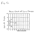
- Figure 12 shows a phase chart of the lane change.
- segment F the azimuth angle decreases, and the relative velocity increases.
- Segment G is an intersection point between segments F and H.
- segment H the azimuth angle continues to decrease, but the relative velocity also decreases in contrast to segment F.
- Figure 13 shows the phase chart of the curve example and the phase chart of the lane change example on a single chart. Only Case B of the curve example is shown on this chart. From the comparison of the two phase charts the characteristics of the two examples change after about 1°. Accordingly, in the example of the lane change, the relative velocity begins to decrease after the azimuth angle has changed by about 1°. In contrast, the relative velocity in the curve example continues to increase even after the azimuth angle has changed by 1°.
- FIG. 14 the target vehicle is exiting from the road onto an exit ramp.
- both vehicles are initially traveling at a speed of 108 km/h like the previous examples.
- the target vehicle slows about 20% before changing directions to exit.
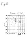
- Figure 15 shows a trace of the travel paths of the two vehicles along an X-axis and a Y-axis. Initially, the target vehicle and the ACC vehicle travel in the same lane and in the same direction. The target vehicle then shifts left as it exists, while the ACC vehicle stays in the right lane and continues traveling straight. The portion where the target vehicle is exiting is denoted as Segment J, and the remaining portion where the target vehicle is traveling straight again on the exit ramp is denoted Segment K.
- Figure 16 shows another trace of the two vehicles along the Y-axis versus velocity. The velocity of the target vehicle is shown decreasing from 108 km/h to about 87 km/h. This decrease in velocity is denoted Segment I.
- the target vehicle After the target vehicle slows to about 87 km/h, the target vehicle maintains a constant velocity of about 87 km/h, and the ACC vehicle maintains a faster velocity of 108 km/h.
- the target vehicle slows before changing direction (i.e., Segment I occurs before Segments J and K), but it should be recognized that other variations are also possible.
- Figure 17 shows a phase chart of the exit example.
- the relative velocity increases from 0 km/h to about 21 km/h, but the azimuth angle remains constant at 0°. This reflects the velocity reduction prior to the direction change while both vehicles are still in the same lane.
- the relative velocity increases slowly to about 23 km/h as the azimuth angle decreases to about 1.5°. The relative velocity then decreases back to about 21 km/h as the azimuth angle continues to decrease to about 3°.
- the relative velocity remains constant at about 21 km/h, and the azimuth angle continues to decrease.
- FIG 18 a flow chart is shown for testing whether a target vehicle is traveling along a curve or whether the target vehicle is changing lanes or exiting.
- the relative velocity and azimuth angle between the ACC vehicle and the target vehicle is measured 10.
- Other relative positional data may also be computed and used to define the changing spatial relationship between the target vehicle and the ACC vehicle.
- the velocity of the ACC vehicle called the ACC velocity
- the lane curvature of the ACC vehicle is estimated from the Yaw rate and/or steering angle.
- a locus is then calculated using the relative velocity and azimuth angle 14.
- the ACC then tests whether the ACC vehicle is traveling along a curve based on the time average of the estimated curvature 16. If the ACC vehicle is judged to be on a straight line, the ACC tests whether the target vehicle is approaching the edge of the lane 18. If the target vehicle is judged to be approaching the lane edge, the locus is compared with stored patterns for curve entering and lane changing possibilities 18a. If the nearest pattern corresponds to curve entering, the ACC continues tracking the target vehicle 18b. On the other hand, if the nearest pattern corresponds to lane changing, the ACC stops tracking the target vehicle 18b. Preferably the test is performed after the azimuth angle becomes greater than 1.5°, since this makes the change in the locus more evident between curve entering and lane changing possibilities. Furthermore, when the discrepancy between the measured locus and the pattern for curve entering is similar to the discrepancy between the measured locus and lane changing, the ACC preferably judges that the target vehicle is traveling along a curve.
- a test is performed to determine when the relative velocity and azimuth angle begin to decrease 20.
- the locus is then compared with stored patterns for curve exiting and lane changing possibilities 20a. If the nearest pattern corresponds to the curve exiting, the ACC continues tracking the target vehicle 20b. On the hand, if the nearest pattern corresponds to lane changing, the ACC stops tracking the target vehicle 20b.
- the ECU 38 tracks a target vehicle through a curve.
- the ACC ECU 38 receives inputs from a number of vehicle sensors including a radar sensor 30, a yaw rate sensor 32, a steering angle sensor 34 and a vehicle speed sensor 36.
- the ACC ECU 38 uses data obtained from these sensors to control the vehicle's speed by adjusting the throttle 40 or the brake 42.
- the ACC ECU 38 maintains a substantially constant distance between a target vehicle and the ACC vehicle through a curve by monitoring an increasing change between the travel direction of the target vehicle and the travel direction of the ACC vehicle or by monitoring the azimuth angle and relative velocity between the target and ACC vehicles.
- the ACC ECU 38 determines that the target vehicle is changing lanes if the change in direction between the two vehicles begins to decrease. Typically, the radar measurement is made every 0.1 second. Therefore, judgment based on the locus should be started every 0.1 second after the azimuth angle becomes larger than 1.5° for the possibilities of entering a curve or changing a lane. After determining that the target vehicle is changing lanes, the ACC vehicle changes from ACC mode to CC mode.
- the judgment is made on the basis of a pattern comparison.
- the locus between relative velocity and azimuth angle starts to return toward the original point.
- the target is determined to be changing lanes.
- the ACC vehicle starts the judgment at 1.5° of the azimuth angle and continues the judgment every 0.1° until 3.5° for curve entering or lane changing.
- the azimuth angle is about 3°. Therefore, the azimuth angle should be monitored for at least 3°.
- the judgment will usually be made before 3°. This test can be achieved by monitoring the slope of the azimuth angle, i.e., d ⁇ /dV R , where ⁇ and V R are azimuth angle and relative velocity of the target vehicle, respectively.
- the ACC ECU 38 disengages the ACC and adjusts the speed of the ACC vehicle to a preset speed. On the other hand, if a curve is detected, the ACC ECU 38 keeps the ACC engaged and adjusts the speed of the ACC vehicle to match the speed of the target vehicle. Other test intervals may also be used, such as between 1° and 2° or between 1.3° and 1.8°.
- the ACC ECU 38 monitors a change in azimuth angle between the ACC vehicle and the target vehicle.
- the ACC ECU 38 additionally or alternatively monitors relative velocity between the vehicles.
- the ACC ECU 38 constructs a phase chart from both the azimuth angle and the relative velocity. The ACC ECU 38 monitors the phase chart both when the target vehicle enters and exits the curve and also when both vehicles are traveling along the curve, thus improving tracking of the target vehicle.
Landscapes
- Engineering & Computer Science (AREA)
- Transportation (AREA)
- Mechanical Engineering (AREA)
- Chemical & Material Sciences (AREA)
- Combustion & Propulsion (AREA)
- Automation & Control Theory (AREA)
- Traffic Control Systems (AREA)
- Control Of Driving Devices And Active Controlling Of Vehicle (AREA)
Abstract
Description
- The present invention relates generally to automotive vehicles, and more particularly, to a cruise control system.
- Cruise control systems are well known in the automotive arts and generally make driving an automotive vehicle easier by automatically adjusting the speed of the vehicle without intervention by the driver. Traditionally, cruise control systems have been designed to maintain a constant speed that is preset by the driver. Thus, in traditional systems, the driver accelerates the vehicle until the vehicle is travelling at the desired speed. The driver then initiates the cruise control by pushing the cruise control button on the steering column or dashboard. Once engaged, the cruise control continuously monitors the speed of the driver's vehicle and automatically adjusts the speed in order to maintain the preset speed.
- While traditional cruise control systems have been widely accepted by automotive drivers, several disadvantages exist. Traditional cruise control systems are generally ineffective when a moderate amount of traffic exists on a roadway. In these situations, the speed of the surrounding vehicles fluctuates more often and with greater variation. Moderate traffic levels also provide less room for the driver to avoid slower and faster moving vehicles. In moderate traffic the driver must adjust the vehicle speed manually without using the cruise control since it is often difficult or impossible to maintain a constant speed.
- Another disadvantage arises when a driver wishes to maintain a certain distance with another vehicle. This often occurs when a group of people are travelling together in two or more vehicles. In this situation, the lead vehicle may use a cruise control system to maintain a constant speed. However, the other vehicles encounter difficulties attempting to use traditional cruise control systems to follow the lead vehicle. Traditional cruise control systems usually do not provide precise enough selection of the preset speed to allow one vehicle to match the speed of another vehicle. Another problem is that following drivers are usually unable to visually perceive the exact speed of the lead vehicle. Thus, when drivers try to use traditional cruise control systems to follow a lead vehicle, the following vehicle usually slowly encroaches upon or slowly falls further behind the lead vehicle. As a result, the driver is required to regularly adjust the preset speed of the cruise control system or may choose to manually control the vehicle speed. Following a lead vehicle can also be difficult when the lead vehicle is not using a cruise control system to maintain a constant speed.
- Adaptive cruise control ("ACC") systems may eliminate these problems by allowing a driver to maintain the same speed as a target vehicle. Accordingly, a driver in a vehicle equipped with ACC ("the ACC vehicle") typically maneuvers the ACC vehicle behind a lead vehicle ("the target vehicle") and engages the ACC system. The ACC then tracks the target vehicle and automatically adjusts the speed of the ACC vehicle in order to maintain the distance between the ACC vehicle and the target vehicle.
- One problem with current ACC systems is that the ACC usually has trouble tracking the target vehicle along curves in the road. Typically, ACC systems are designed to travel at the preset speed when no target vehicle exists directly ahead of the ACC vehicle. This is often called CC mode (Conventional Cruise Control), while the tracking function is called ACC mode. An ACC will change from the ACC mode to the CC mode when the target vehicle changes lanes out of the lane of the ACC vehicle. When the ACC disengages, the cruise control system typically selects a preset speed chosen either by the manufacturer or the driver and maintains the speed of the vehicle at the preset speed. Therefore, when the target vehicle changes lanes away from the ACC vehicle, the ACC disengages and the vehicle maintains a preset speed.
- When the target vehicle remains in the same lane as the ACC vehicle and instead enters a curve in the road, the ACC desirably continues tracking the target vehicle and maintaining the same speed as the target vehicle. However, there are no effective methods to distinguish between the cases of a lane change and curve travel by the target vehicle. Usually, current ACCs determine that the preceding vehicle has changed lanes. After the ACC vehicle enters the curve, the ACC then determines that the preceding vehicle is a target. Namely, the mode of the ACC switches as follows: first ACC mode, next CC mode, then ACC mode. Desirably, however, the ACC vehicle should remain in the ACC mode during the entire curve travel.
- The present invention is defined by the following claims, and nothing in this section should be taken as a limitation on those claims. By way of introduction, the embodiments described below include an ACC system for deciding whether a target vehicle is traveling along a curve or whether the target vehicle is changing lanes. The ACC measures an azimuth angle and a relative velocity between the ACC vehicle and the target vehicle. After the target vehicle enters the curve or starts the lane change, the relative velocity and the azimuth angle starts changing. The temporal locus is remarkably different between the two possibilities since the change in velocity and azimuth angle is different for each possibility. When the angle is getting larger than 1.5 degrees, the ACC starts judging whether the preceding vehicle is entering a curve or changing lanes. The judgment can be made by comparing several locus patterns of the preceding vehicle during curve travel and lane changes.
- The invention, including its construction and method of operation, is illustrated diagrammatically in the drawings, in which:
- Figure 1A is a plan view of an ACC vehicle tracking a target vehicle, showing both vehicles traveling on a straight portion of a road before a curve;
- Figure 1B is a view of the velocity vectors of the ACC vehicle and the target vehicle of Figure 1A showing zero relative velocity between the vehicles;
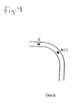
- Figure 2 is a plan view of the ACC vehicle and the target vehicle, showing the target vehicle traveling along the curve and the ACC vehicle traveling along the straight portion before the curve;
- Figure 3A is a plan view of the ACC vehicle and the target vehicle, showing both vehicles traveling along the curve.
- Figure 3B is a view of the velocity vectors of both vehicles of Figure 3A, showing the relative velocity between the vehicles;
- Figure 3C is another view of the velocity vectors of both vehicles of Figure 3A, showing an alternative way to calculate the relative velocity;
- Figure 3D is a plan view of the ACC vehicle and target vehicle, showing the azimuth angle between the vehicles;
- Figure 4 is a plan view of the ACC vehicle and the target vehicle, showing the target vehicle traveling along a straight portion after the curve and the ACC vehicle traveling along the curve;
- Figure 5 is a plan view of the ACC vehicle and the target vehicle, showing both vehicles traveling along the straight portion after the curve;
- Figure 6 is a trace of the curve from Figures 1-5 along an X-axis and a Y-axis;
- Figure 7 is a chart of the vehicle example from Figures 1-5, showing azimuth angle versus time;
- Figure 8 is a phase chart of the vehicle example from Figures 1-5, showing azimuth angle versus relative velocity;
- Figure 9 is a plan view of a target vehicle changing lanes away from an ACC vehicle;
- Figure 10 is a trace of the lane change from Figure 9 along an X-axis and a Y-axis;
- Figure 11 is a chart of the vehicle example from Figure 9, showing azimuth angle versus time;
- Figure 12 is a phase chart of the vehicle example from Figure 9, showing azimuth angle versus relative velocity;
- Figure 13 is a combined phase chart of the phase charts from Figures 8 and 12;
- Figure 14 is a plan view of a target vehicle exiting a road and an ACC vehicle staying on the road;
- Figure 15 is a trace of the exit from Figure 14 along an X-axis and a Y-axis;
- Figure 16 is a trace of the vehicle example from Figure 14 along the Y-axis versus velocity;
- Figure 17 is a phase chart of the vehicle example from Figure 14, showing azimuth angle versus relative velocity;
- Figure 18 is a flow chart of one embodiment showing a test for deciding whether a target vehicle is traveling along a curve or whether the target vehicle is changing lanes; and
- Figure 19 is a block diagram of one embodiment of an ACC system.
-
- Referring now to the figures, an adaptive cruise control ("ACC") system is provided that tracks a target vehicle through a curve, especially at its entrance and exit. Curve travel may generally be described in five different cases. Accordingly, the five cases are shown sequentially in Figures 1-5. Throughout the described examples except where noted, the speed of the target vehicle is 108 km/h, and the speed of the ACC vehicle is 108 km/h. The distance between the two vehicles is 120 m. Additionally, the curve extends 90° between the starting point and the ending point. The radius of the curve is 500 m. The described ACC can track the target vehicle in a variety of curves, speeds, distances and circumstances.
- In Figure 1A, Case A of the curve travel is shown. In Case A, both the ACC vehicle ("ACC" in the figures) and the target vehicle ("T" in the figures) are traveling along a straight portion of the road before entering a curve. The velocity of the ACC vehicle is represented by the arrow labeled VA, and the velocity of the target vehicle is labeled VT. In Figure 1B, the velocity VA of the ACC vehicle and the velocity VT of the target vehicle have the same direction and speed. Therefore, the relative velocity VR between the target vehicle and the ACC vehicle is zero. Likewise, the radial angle and the azimuth angle between the two vehicles are also 0.
- Turning now to Figure 2, Case B is shown. In Case B, the target vehicle has entered the curve. However, the ACC vehicle has not entered the curve and remains on the straight portion of the road before the curve. Since the target vehicle is now traveling along the curve while the ACC vehicle is traveling straight, the velocity direction of the two vehicles is different. Current ACC systems often misinterpret this situation as a lane change, thus disengaging the ACC. However, as described below, the present ACC is able to distinguish Case B from a lane change and continues to track the target vehicle despite the difference in travel direction.
- Turning now to Figure 3A, Case C is shown. In Case C, the ACC vehicle has entered the curve along with the target vehicle. Thus, in the present example where the radius of the curve is constant, both vehicles are traveling along the same radius with the same yaw rates (i.e., lateral movement relative to each vehicle). Accordingly, the radial angle between the ACC vehicle and the target vehicle is calculated to be about 14° ((360 * 120)/(2 * π * 500)). The velocity arrows VA and VT in Figure 3A demonstrate the difference in velocity direction between the ACC vehicle and the target vehicle.
- In Figure 3B, the velocity VA of the ACC vehicle and the velocity VT of the target vehicle are drawn to show the relative velocity VR between the two vehicles. Assuming that the magnitude of velocity VA (i.e., speed) of the ACC vehicle and the magnitude of velocity VT of the target vehicle are the same, the relative velocity is calculated to be about 26 km/h.
- Figure 3C shows another calculation of the relative velocity. The velocity VT of the target vehicle is divided into a horizontal component VTX and a vertical component VTY. The velocity VA of the ACC vehicle is also divided into a horizontal component VAX and a vertical component VAY. The relative velocity is calculated with the formula VR = SQRT [(VTX - VAX)2 + (VTY - VAY)2].
- Figure 3D shows the azimuth angle of the target vehicle. The azimuth angle is the angle of the target vehicle from the forward line of sight of the ACC vehicle. The azimuth angle is calculated by first determining the horizontal distance x and the vertical distance y of the target vehicle from the ACC vehicle. Accordingly, the horizontal distance is calculated as X = R * COS - R, and the vertical distance is calculated as Y = R SIN , where is the radial angle between the vehides. The azimuth angle is calculated as = ATAN (X/Y). In the present example, the azimuth angle is about 7°. Geometrically, the azimuth angle is one-half of the radial angle for constant radius curves.
- The relative velocity and azimuth angle may be calculated in a variety of ways, and the examples above are only intended to generally describe relative velocity and azimuth angle.
- Turning now to Figure 4, Case D is shown. In Case D, the target vehicle has exited the curve and is traveling along a straight portion of the road after the curve. However, the ACC vehicle remains in the curve and continues to travel along the curve. This case is similar to Case B described above. The similarity between Case B and Case D will also be further described below.
- Turning now to Figure 5, Case E is shown. In Case E, the ACC vehicle has exited the curve. Thus, both vehicles are traveling along the straight portion of the road after the curve. Therefore, the travel direction of both vehicles is the same. Case E is similar to Case A described above.
- Turning now to Figures 6-8, a trace of the curve is shown in Figure 6. The trace is drawn on an X-axis and a Y-axis and is generally representative of the curve in Figures 1-5. In Figure 7, the change in azimuth angle is shown as the target vehicle and the ACC vehicle travel along the curve. The five cases described above are denoted on the chart. Accordingly, Case A is represented between 0 and about 5 seconds. The azimuth angle remains 0° throughout this case because both vehicles are traveling straight in the same direction. Case B is represented between about 5 and 9 seconds. In this case, the azimuth angle decreases sharply from 0° to about 7°. The azimuth angle is steadily changing throughout this case because the ACC vehicle is still traveling along the straight portion of the road. However, the target vehicle is traveling along the curve and is steadily changing its direction of travel. Case C is represented between about 9 seconds and about 31.5 seconds. The azimuth angle remains about 7° throughout this case because both vehicles are traveling along the constant curve. Thus, the target vehicle is maintaining a constant difference in travel direction from the ACC vehicle. Case D is represented between about 31.5 seconds and 35.5 seconds. In this case, the azimuth angle increases sharply from about 7° to 0°. Like Case B, the azimuth angle steadily changes throughout this case because the target vehicle is traveling along a straight portion of the road but the ACC vehicle is traveling along the curve. Case E is represented between about 35.5 seconds to 40 seconds. Like Case A, the azimuth angle remains 0° throughout this case because both vehicles are traveling straight again in the same direction. Other times and azimuth angles may result from different speeds, curves and distances between vehicles.
- Figure 8 shows a phase chart for each of the five cases. In the chart, Case A is a single point at the origin. As previously described, the azimuth angle remains at 0° throughout this case, and the relative velocity also remains at 0 km/h. Case B is a downward sloping curve that begins at the origin. During this case, the azimuth angle changes from 0° to about 7°, and the relative velocity increases from 0 km/h to about 26 km/h. Case C is a single point between the curves marked B and D. As previously described, the azimuth angle and the relative velocity remain constant during this case. Case D is an upward sloping curve that begins at Case D and ends at the origin. Case D is generally an inverse of Case B, with the azimuth angle changing from about 7° to 0° and the relative velocity decreasing from about 26 km/h to 0 km/h. Case E is a single point at the origin like Case A.
- A phase chart like that shown in Figure 8 may be determined for many kinds of curves. A constant radius curve has been used herein to simplify the description. However, a changing radius curve would produce a similar phase chart. In a changing radius curve, Case C may be a curve instead of a single point, but the general characteristics of the phase chart may be similar to that described above. Moreover, although a left-hand curve has been described, a right-hand curve produces similar results. Multiple linked curves may also be analyzed using the techniques described herein.
- Turning now to Figure 9, an example of a lane change is shown. In this example, both the target vehicle and the ACC vehicle are traveling at 108 km/h like the previous curve example. Initially both vehicles are traveling in the same, right-hand lane. The target vehicle then changes lanes from the right-hand lane to the left-hand lane.
- A trace of the lane change example is shown in Figure 10 along an X-axis and a Y-axis. The travel path of the target vehicle shifts to the left about 4 m after the lane change. However, the travel path of the ACC vehicle does not change and remains straight.
- Figure 11 shows the change in azimuth angle during the lane change. Initially, from 0 to about 5 seconds, both the target vehicle and the ACC vehicle are in the same lane. During this time, the azimuth angle remains 0°. The lane change then occurs between about 5 to about 8.5 seconds. The lane change is denoted with three segments F, G, H. Segment F shows a concave down portion of the change in azimuth angle. Segment G shows an inflection point between segments F and H. Segment H shows a concave up portion of the change in azimuth angle. After the lane change, the azimuth angle now remains constant at about 2°.
- Figure 12 shows a phase chart of the lane change. During segment F, the azimuth angle decreases, and the relative velocity increases. Segment G is an intersection point between segments F and H. During segment H, the azimuth angle continues to decrease, but the relative velocity also decreases in contrast to segment F.
- Figure 13 shows the phase chart of the curve example and the phase chart of the lane change example on a single chart. Only Case B of the curve example is shown on this chart. From the comparison of the two phase charts the characteristics of the two examples change after about 1°. Accordingly, in the example of the lane change, the relative velocity begins to decrease after the azimuth angle has changed by about 1°. In contrast, the relative velocity in the curve example continues to increase even after the azimuth angle has changed by 1°.
- Turning now to Figures 14-17, another lane change example is shown. In Figure 14, the target vehicle is exiting from the road onto an exit ramp. In this example, both vehicles are initially traveling at a speed of 108 km/h like the previous examples. However, in this example, the target vehicle slows about 20% before changing directions to exit.
- Figure 15 shows a trace of the travel paths of the two vehicles along an X-axis and a Y-axis. Initially, the target vehicle and the ACC vehicle travel in the same lane and in the same direction. The target vehicle then shifts left as it exists, while the ACC vehicle stays in the right lane and continues traveling straight. The portion where the target vehicle is exiting is denoted as Segment J, and the remaining portion where the target vehicle is traveling straight again on the exit ramp is denoted Segment K. Figure 16 shows another trace of the two vehicles along the Y-axis versus velocity. The velocity of the target vehicle is shown decreasing from 108 km/h to about 87 km/h. This decrease in velocity is denoted Segment I. After the target vehicle slows to about 87 km/h, the target vehicle maintains a constant velocity of about 87 km/h, and the ACC vehicle maintains a faster velocity of 108 km/h. In this example, the target vehicle slows before changing direction (i.e., Segment I occurs before Segments J and K), but it should be recognized that other variations are also possible.
- Figure 17 shows a phase chart of the exit example. During Segment I, the relative velocity increases from 0 km/h to about 21 km/h, but the azimuth angle remains constant at 0°. This reflects the velocity reduction prior to the direction change while both vehicles are still in the same lane. During Segment J, the relative velocity increases slowly to about 23 km/h as the azimuth angle decreases to about 1.5°. The relative velocity then decreases back to about 21 km/h as the azimuth angle continues to decrease to about 3°. During Segment K, the relative velocity remains constant at about 21 km/h, and the azimuth angle continues to decrease.
- Turning now to Figure 18, a flow chart is shown for testing whether a target vehicle is traveling along a curve or whether the target vehicle is changing lanes or exiting. First, the relative velocity and azimuth angle between the ACC vehicle and the target vehicle is measured 10. Other relative positional data may also be computed and used to define the changing spatial relationship between the target vehicle and the ACC vehicle. Next, the velocity of the ACC vehicle, called the ACC velocity, is measured, and the lane curvature of the ACC vehicle is estimated from the Yaw rate and/or steering angle. A locus is then calculated using the relative velocity and azimuth angle 14.
- The ACC then tests whether the ACC vehicle is traveling along a curve based on the time average of the estimated
curvature 16. If the ACC vehicle is judged to be on a straight line, the ACC tests whether the target vehicle is approaching the edge of thelane 18. If the target vehicle is judged to be approaching the lane edge, the locus is compared with stored patterns for curve entering andlane changing possibilities 18a. If the nearest pattern corresponds to curve entering, the ACC continues tracking thetarget vehicle 18b. On the other hand, if the nearest pattern corresponds to lane changing, the ACC stops tracking thetarget vehicle 18b. Preferably the test is performed after the azimuth angle becomes greater than 1.5°, since this makes the change in the locus more evident between curve entering and lane changing possibilities. Furthermore, when the discrepancy between the measured locus and the pattern for curve entering is similar to the discrepancy between the measured locus and lane changing, the ACC preferably judges that the target vehicle is traveling along a curve. - When the ACC vehicle and target vehicle are both traveling along a curve, a test is performed to determine when the relative velocity and azimuth angle begin to decrease 20. The locus is then compared with stored patterns for curve exiting and
lane changing possibilities 20a. If the nearest pattern corresponds to the curve exiting, the ACC continues tracking thetarget vehicle 20b. On the hand, if the nearest pattern corresponds to lane changing, the ACC stops tracking thetarget vehicle 20b. - In Figure 18, the operation of the ACC for stationary conditions, in which the target vehicle and ACC vehicle are both traveling in a straight lane or along the same curve, is omitted since conventional ACC operations may be used for these conditions. Also, when measuring the velocity of the ACC vehicle, the Yaw rate and/or steering angle may be used since the relative velocity change and azimuth angle change is derived from the velocity of the ACC vehicle.
- Turning now to Figure 19, an ACC electronic control unit ("ECU") 38 is shown. The
ECU 38 tracks a target vehicle through a curve. TheACC ECU 38 receives inputs from a number of vehicle sensors including aradar sensor 30, ayaw rate sensor 32, asteering angle sensor 34 and avehicle speed sensor 36. TheACC ECU 38 uses data obtained from these sensors to control the vehicle's speed by adjusting thethrottle 40 or thebrake 42. TheACC ECU 38 maintains a substantially constant distance between a target vehicle and the ACC vehicle through a curve by monitoring an increasing change between the travel direction of the target vehicle and the travel direction of the ACC vehicle or by monitoring the azimuth angle and relative velocity between the target and ACC vehicles. After a test interval of about 1.5°, theACC ECU 38 determines that the target vehicle is changing lanes if the change in direction between the two vehicles begins to decrease. Typically, the radar measurement is made every 0.1 second. Therefore, judgment based on the locus should be started every 0.1 second after the azimuth angle becomes larger than 1.5° for the possibilities of entering a curve or changing a lane. After determining that the target vehicle is changing lanes, the ACC vehicle changes from ACC mode to CC mode. - In Figure 18, the judgment is made on the basis of a pattern comparison. However, as a simple judgment, the locus between relative velocity and azimuth angle starts to return toward the original point. Thus, the target is determined to be changing lanes. In this judgment, the ACC vehicle starts the judgment at 1.5° of the azimuth angle and continues the judgment every 0.1° until 3.5° for curve entering or lane changing. For example, when headway between the vehicles is 40 m and lateral displacement is 2 m, the azimuth angle is about 3°. Therefore, the azimuth angle should be monitored for at least 3°. However, the judgment will usually be made before 3°. This test can be achieved by monitoring the slope of the azimuth angle, i.e., d/dVR, where and VR are azimuth angle and relative velocity of the target vehicle, respectively.
- If a lane change is detected, the
ACC ECU 38 disengages the ACC and adjusts the speed of the ACC vehicle to a preset speed. On the other hand, if a curve is detected, theACC ECU 38 keeps the ACC engaged and adjusts the speed of the ACC vehicle to match the speed of the target vehicle. Other test intervals may also be used, such as between 1° and 2° or between 1.3° and 1.8°. In one embodiment, theACC ECU 38 monitors a change in azimuth angle between the ACC vehicle and the target vehicle. In another embodiment, theACC ECU 38 additionally or alternatively monitors relative velocity between the vehicles. In still another embodiment, theACC ECU 38 constructs a phase chart from both the azimuth angle and the relative velocity. TheACC ECU 38 monitors the phase chart both when the target vehicle enters and exits the curve and also when both vehicles are traveling along the curve, thus improving tracking of the target vehicle. - While preferred embodiments of the invention have been described, it should be understood that the invention is not so limited, and modifications may be made without departing from the invention. The scope of the invention is defined by the appended claims, and all devices that come within the meaning of the claims, either literally or by equivalence, are intended to be embraced therein.
Claims (18)
- An adaptive cruise control system comprising a sensor determining a travel direction of a first vehicle and a travel direction of a second vehicle; an electronic control unit operable to receive said determinations from said sensor and monitor an increasing change between said first vehicle travel direction and said second vehicle travel direction; wherein said electronic control unit controls a speed of said first vehicle as a function of said monitoring.
- The adaptive cruise control system according to Claim 1, wherein said electronic control unit determines whether said change in travel directions continues to increase or begins to decrease after a test interval.
- The adaptive cruise control system according to Claim 2, wherein said test interval is an angle between said first and second vehicles.
- The adaptive cruise control system according to Claim 3, wherein said test interval angle is an azimuth angle.
- The adaptive cruise control system according to Claim 4, wherein said test interval is about 1.5°.
- The adaptive cruise control system according to Claim 4, wherein said test interval is between 1° and 2°.
- The adaptive cruise control system according to Claim 6, wherein said change in travel directions is a function of a change in relative velocity, whereby said monitoring comprises analyzing a phase chart of azimuth angle versus relative velocity, said testing thereby deciding whether said second vehicle is traveling along a curve or whether said second vehicle is changing lanes, said lane change decision occurring when said relative velocity continues to increase after said azimuth angle test interval, said curve travel decision occurring when said relative velocity begins to decrease after said azimuth angle test interval.
- The adaptive cruise control system according to Claim 4, wherein said test interval is between 1.3° and 1.8°.
- The adaptive cruise control system according to Claim 1, wherein said electronic control unit determines whether said second vehicle is traveling along a curve or is changing a lane, said curve travel decision occurring when a segment of said change in travel directions continues to increase after a test interval, said lane change decision occurring when said segment decreases after said test interval, wherein said electronic control unit adjusts a throttle to maintain a constant distance between said first and second vehicles when said curve travel decision occurs and said electronic control unit adjusts said throttle to maintain a preset speed when said lane change decision occurs.
- The adaptive cruise control system according to Claim 9, wherein said electronic control unit tests said determination repetitively for overlapping test intervals.
- The adaptive cruise control system according to Claim 9, wherein said electronic control unit tests said determination for a single test interval when said change in travel direction begins to increase.
- The adaptive cruise control system according to Claim 9, wherein said change in travel direction is a relative velocity.
- The adaptive cruise control system according to Claim 12, wherein said test interval is an azimuth angle.
- The adaptive cruise control system according to Claim 13, wherein said test interval is about 1.5°.
- The adaptive cruise control system according to Claim 13, wherein said test interval is between 1° and 2°.
- The adaptive cruise control system according to Claim 15, wherein said electronic control unit tests said determination repetitively for overlapping test intervals.
- The adaptive cruise control system according to Claim 15, wherein said electronic control unit tests said determination for a single test interval when said change in travel direction begins to increase.
- The adaptive cruise control system according to Claim 13, wherein said test interval is between 1.3° and 1.8°.
Applications Claiming Priority (2)
| Application Number | Priority Date | Filing Date | Title |
|---|---|---|---|
| US09/815,187 US6795765B2 (en) | 2001-03-22 | 2001-03-22 | Tracking of a target vehicle using adaptive cruise control |
| US815187 | 2001-03-22 |
Publications (2)
| Publication Number | Publication Date |
|---|---|
| EP1243457A2 true EP1243457A2 (en) | 2002-09-25 |
| EP1243457A3 EP1243457A3 (en) | 2004-11-17 |
Family
ID=25217120
Family Applications (1)
| Application Number | Title | Priority Date | Filing Date |
|---|---|---|---|
| EP02005751A Withdrawn EP1243457A3 (en) | 2001-03-22 | 2002-03-13 | Tracking of a target vehicle using adaptive cruise control |
Country Status (2)
| Country | Link |
|---|---|
| US (1) | US6795765B2 (en) |
| EP (1) | EP1243457A3 (en) |
Cited By (5)
| Publication number | Priority date | Publication date | Assignee | Title |
|---|---|---|---|---|
| GB2390440A (en) * | 2002-05-21 | 2004-01-07 | Visteon Global Tech Inc | Target vehicle identification based on the theoretical relationship between the azimuth angle and relative velocity |
| GB2396339A (en) * | 2002-11-21 | 2004-06-23 | Visteon Global Tech Inc | Preceding vehicle lane change identification |
| CN109753056A (en) * | 2017-11-07 | 2019-05-14 | 北京图森未来科技有限公司 | A kind of the speed dynamic control method and device of automatic navigation of vehicle |
| CN113104034A (en) * | 2021-04-30 | 2021-07-13 | 东风汽车集团股份有限公司 | ACC self-adaptive cruise safety control method and device |
| US11753008B2 (en) | 2017-07-01 | 2023-09-12 | Tusimple, Inc. | System and method for adaptive cruise control with proximate vehicle detection |
Families Citing this family (25)
| Publication number | Priority date | Publication date | Assignee | Title |
|---|---|---|---|---|
| DE10114470A1 (en) * | 2001-03-24 | 2002-09-26 | Bosch Gmbh Robert | Motor vehicle lane maintenance and speed regulation device has steering controller switched to standby state by independent main switch, activated by same switch-on signal as speed regulator |
| KR100411102B1 (en) * | 2001-06-20 | 2003-12-12 | 현대자동차주식회사 | Automobile intelligent cruise control system and method thereof |
| US6944543B2 (en) * | 2001-09-21 | 2005-09-13 | Ford Global Technologies Llc | Integrated collision prediction and safety systems control for improved vehicle safety |
| DE10149146A1 (en) * | 2001-10-05 | 2003-04-17 | Bosch Gmbh Robert | Speed regulator with distance regulating function for motor vehicle, has monitoring module for detecting situation with danger of objects not detected by location system being in immediate vicinity |
| US8718919B2 (en) * | 2002-04-23 | 2014-05-06 | Robert Bosch Gmbh | Method and apparatus for lane recognition for a vehicle |
| DE10218010A1 (en) * | 2002-04-23 | 2003-11-06 | Bosch Gmbh Robert | Method and device for lateral guidance support in motor vehicles |
| JP4125168B2 (en) * | 2003-04-02 | 2008-07-30 | 本田技研工業株式会社 | Vehicle travel control device |
| JP4781707B2 (en) * | 2005-04-15 | 2011-09-28 | 富士重工業株式会社 | Vehicle driving support device |
| CA2622625A1 (en) * | 2005-09-14 | 2007-03-22 | O-Ya!, Inc. | Networked information indexing and search apparatus and method |
| SE0502819L (en) * | 2005-12-13 | 2006-12-19 | Scania Cv Abp | Data Generation System |
| SE528566C2 (en) * | 2005-12-13 | 2006-12-19 | Scania Cv Abp | Adaptive cruise control system for motor vehicle, simultaneously detects multiple vehicles in front and generates control sequence for each detected vehicle |
| JP4432941B2 (en) * | 2006-08-07 | 2010-03-17 | トヨタ自動車株式会社 | Steering support device |
| JP5146542B2 (en) * | 2008-12-26 | 2013-02-20 | トヨタ自動車株式会社 | Traveling route estimation device and traveling route estimation method used in the device |
| JP5363906B2 (en) * | 2009-08-05 | 2013-12-11 | 株式会社アドヴィックス | Vehicle speed control device |
| US8543309B2 (en) | 2011-01-10 | 2013-09-24 | Bendix Commercial Vehicle Systems Llc | ACC and AM braking range variable based on lateral and longitudinal position of forward vehicle and curvature of road |
| US8972147B2 (en) | 2011-01-10 | 2015-03-03 | Bendix Commercial Vehicle Systems Llc | ACC and AM braking range variable based on internal and external factors |
| GB2500426B (en) | 2012-03-22 | 2014-09-10 | Jaguar Land Rover Ltd | Autonomous cruise control |
| JP5981332B2 (en) * | 2012-12-21 | 2016-08-31 | 株式会社日本自動車部品総合研究所 | Travel route generator |
| DE102013211427B4 (en) * | 2013-06-18 | 2016-10-13 | Continental Automotive Gmbh | Method and device for determining a driving state of an external motor vehicle |
| JP6567936B2 (en) * | 2015-09-30 | 2019-08-28 | 株式会社Subaru | Steering support control device |
| TWI602725B (en) * | 2015-10-13 | 2017-10-21 | 財團法人車輛研究測試中心 | Method and apparatus for vehicle path tracking with error correction |
| JP6658674B2 (en) * | 2017-06-08 | 2020-03-04 | トヨタ自動車株式会社 | Driving support system |
| US10586455B2 (en) * | 2017-10-19 | 2020-03-10 | Veoneer Us, Inc. | Systems and methods for vehicle lane change detection |
| CN111189650A (en) * | 2020-01-22 | 2020-05-22 | 长安大学 | Unmanned vehicle cooperative driving capability test system and test method |
| CN112896161B (en) * | 2021-02-08 | 2022-06-21 | 杭州电子科技大学 | Electric automobile ecological self-adaptation cruise control system based on reinforcement learning |
Family Cites Families (34)
| Publication number | Priority date | Publication date | Assignee | Title |
|---|---|---|---|---|
| JPH04245600A (en) | 1991-01-31 | 1992-09-02 | Fujitsu Ten Ltd | Radar system collision warning equipment for automatic vehicle |
| JP3164439B2 (en) * | 1992-10-21 | 2001-05-08 | マツダ株式会社 | Obstacle detection device for vehicles |
| US5680097A (en) * | 1992-12-10 | 1997-10-21 | Mazda Motor Corporation | Vehicle run safety apparatus |
| US5388048A (en) | 1993-02-16 | 1995-02-07 | Silicon Heights Limited | Vehicle anti-collison device |
| DE4407757A1 (en) | 1993-03-08 | 1994-09-15 | Mazda Motor | Device for detecting obstacles for a vehicle |
| JP3438279B2 (en) | 1993-05-19 | 2003-08-18 | マツダ株式会社 | Vehicle speed control device |
| WO1995001577A1 (en) * | 1993-07-02 | 1995-01-12 | Gec-Marconi Avionics (Holdings) Ltd. | Road vehicle cruise control system |
| JPH0717347A (en) | 1993-07-07 | 1995-01-20 | Mazda Motor Corp | Obstacle detecting device for automobile |
| US5402129A (en) | 1993-08-04 | 1995-03-28 | Vorad Safety Systems, Inc. | Monopulse azimuth radar system for automotive vehicle tracking |
| JP2799375B2 (en) | 1993-09-30 | 1998-09-17 | 本田技研工業株式会社 | Anti-collision device |
| US5648905A (en) * | 1993-12-07 | 1997-07-15 | Mazda Motor Corporation | Traveling control system for motor vehicle |
| SE516317C2 (en) | 1994-06-07 | 2001-12-17 | Saabtech Electronics Ab | Procedure for determining the lane of a vehicle ahead |
| JP3380624B2 (en) * | 1994-09-14 | 2003-02-24 | マツダ株式会社 | Vehicle running state detection device |
| US5745870A (en) | 1994-09-14 | 1998-04-28 | Mazda Motor Corporation | Traveling-path prediction apparatus and method for vehicles |
| GB9425096D0 (en) * | 1994-12-13 | 1995-02-08 | Lucas Ind Plc | Apparatus and method for cruise control |
| JP3209872B2 (en) | 1995-02-13 | 2001-09-17 | 富士通テン株式会社 | Inter-vehicle distance detection device |
| JP3257410B2 (en) | 1995-11-24 | 2002-02-18 | トヨタ自動車株式会社 | In-vehicle scanning radar |
| JP3331882B2 (en) * | 1995-12-27 | 2002-10-07 | 株式会社デンソー | Central axis deflection amount calculating device, central axis deflection amount correcting device, and inter-vehicle control device of vehicle obstacle detection device |
| GB9606384D0 (en) * | 1996-03-26 | 1996-06-05 | Jaguar Cars | Cruise control systems |
| JP3314623B2 (en) | 1996-08-12 | 2002-08-12 | トヨタ自動車株式会社 | In-vehicle scanning radar |
| DE19637245C2 (en) * | 1996-09-13 | 2000-02-24 | Bosch Gmbh Robert | Method and device for regulating the speed of a vehicle |
| JP3843502B2 (en) | 1996-09-30 | 2006-11-08 | マツダ株式会社 | Vehicle motion recognition device |
| US6085151A (en) | 1998-01-20 | 2000-07-04 | Automotive Systems Laboratory, Inc. | Predictive collision sensing system |
| US6026347A (en) | 1997-05-30 | 2000-02-15 | Raytheon Company | Obstacle avoidance processing method for vehicles using an automated highway system |
| DE19833065B4 (en) | 1997-07-22 | 2010-04-15 | DENSO CORPORATION, Kariya-shi | An angular displacement determining device for determining the angular displacement of the radar center axis for use in a self-locating obstacle detection system |
| US5964822A (en) * | 1997-08-27 | 1999-10-12 | Delco Electronics Corp. | Automatic sensor azimuth alignment |
| US5926126A (en) * | 1997-09-08 | 1999-07-20 | Ford Global Technologies, Inc. | Method and system for detecting an in-path target obstacle in front of a vehicle |
| US5959569A (en) * | 1997-10-09 | 1999-09-28 | Eaton Vorad Technologies, L.L.C. | Method and apparatus for in path target determination for an automotive vehicle using a gyroscopic device |
| DE19749086C1 (en) * | 1997-11-06 | 1999-08-12 | Daimler Chrysler Ag | Device for determining data indicating the course of the lane |
| JP2930236B1 (en) | 1998-01-26 | 1999-08-03 | 本田技研工業株式会社 | Radar equipment |
| DE19804944C2 (en) | 1998-02-07 | 2000-04-20 | Volkswagen Ag | Automatic distance control method for motor vehicles |
| US6087995A (en) | 1999-02-17 | 2000-07-11 | Anritsu Company | Universal autoradar antenna alignment system |
| US6438491B1 (en) * | 1999-08-06 | 2002-08-20 | Telanon, Inc. | Methods and apparatus for stationary object detection |
| JP3427809B2 (en) * | 2000-03-09 | 2003-07-22 | 株式会社デンソー | Vehicle road shape recognition method and apparatus, recording medium |
-
2001
- 2001-03-22 US US09/815,187 patent/US6795765B2/en not_active Expired - Lifetime
-
2002
- 2002-03-13 EP EP02005751A patent/EP1243457A3/en not_active Withdrawn
Non-Patent Citations (1)
| Title |
|---|
| None |
Cited By (9)
| Publication number | Priority date | Publication date | Assignee | Title |
|---|---|---|---|---|
| GB2390440A (en) * | 2002-05-21 | 2004-01-07 | Visteon Global Tech Inc | Target vehicle identification based on the theoretical relationship between the azimuth angle and relative velocity |
| GB2390440B (en) * | 2002-05-21 | 2004-06-09 | Visteon Global Tech Inc | Target vehicle identification based on the theoretical relationship between the azimuth angle and relative velocity |
| US6753804B2 (en) | 2002-05-21 | 2004-06-22 | Visteon Global Technologies, Inc. | Target vehicle identification based on the theoretical relationship between the azimuth angle and relative velocity |
| GB2396339A (en) * | 2002-11-21 | 2004-06-23 | Visteon Global Tech Inc | Preceding vehicle lane change identification |
| GB2396339B (en) * | 2002-11-21 | 2004-11-24 | Visteon Global Tech Inc | Method and system for identifying a lane change |
| US11753008B2 (en) | 2017-07-01 | 2023-09-12 | Tusimple, Inc. | System and method for adaptive cruise control with proximate vehicle detection |
| CN109753056A (en) * | 2017-11-07 | 2019-05-14 | 北京图森未来科技有限公司 | A kind of the speed dynamic control method and device of automatic navigation of vehicle |
| CN113104034A (en) * | 2021-04-30 | 2021-07-13 | 东风汽车集团股份有限公司 | ACC self-adaptive cruise safety control method and device |
| CN113104034B (en) * | 2021-04-30 | 2022-05-20 | 东风汽车集团股份有限公司 | ACC self-adaptive cruise safety control method and device |
Also Published As
| Publication number | Publication date |
|---|---|
| US20020138193A1 (en) | 2002-09-26 |
| EP1243457A3 (en) | 2004-11-17 |
| US6795765B2 (en) | 2004-09-21 |
Similar Documents
| Publication | Publication Date | Title |
|---|---|---|
| US6795765B2 (en) | Tracking of a target vehicle using adaptive cruise control | |
| US11173902B2 (en) | Vehicle control device | |
| US5529139A (en) | Vehicle speed control system | |
| EP1034963B1 (en) | Running controller for automobile | |
| US5479173A (en) | Obstacle sensing apparatus for vehicles | |
| US6643588B1 (en) | Geometric based path prediction method using moving and stop objects | |
| US7617037B2 (en) | System for automatically monitoring a motor vehicle | |
| JP2799375B2 (en) | Anti-collision device | |
| JP4571757B2 (en) | Method and apparatus for controlling the running speed of a vehicle | |
| US5585798A (en) | Obstacle detection system for automotive vehicle | |
| JP4005597B2 (en) | Side guide support method and apparatus for vehicle | |
| KR100667995B1 (en) | Method and device for determining the future course of a motor vehicle | |
| US8447488B2 (en) | Device for longitudinally guiding a motor vehicle | |
| US6889161B2 (en) | Method for recognizing a change in lane of a vehicle | |
| EP0677799B1 (en) | Vehicle travel aiding device | |
| US20050015203A1 (en) | Lane-changing support system | |
| EP2405416B1 (en) | Adaptive cruise control method and system for controlling speed of vehicle | |
| US10990108B2 (en) | Vehicle control system | |
| EP1065087B1 (en) | Automobile running control system for optimum inter-vehicle spacing | |
| JP3548009B2 (en) | Travel control device for vehicles | |
| JPH0757182A (en) | Safety device for vehicle | |
| US8094000B2 (en) | Surroundings monitoring apparatus for a motor vehicle | |
| JPH05203737A (en) | Obstacle detector for vehicle | |
| KR100469773B1 (en) | Method and apparatus for correcting a curve radius | |
| JPH06150200A (en) | Travelling controller for vehicle |
Legal Events
| Date | Code | Title | Description |
|---|---|---|---|
| PUAI | Public reference made under article 153(3) epc to a published international application that has entered the european phase |
Free format text: ORIGINAL CODE: 0009012 |
|
| AK | Designated contracting states |
Kind code of ref document: A2 Designated state(s): AT BE CH CY DE DK ES FI FR GB GR IE IT LI LU MC NL PT SE TR |
|
| AX | Request for extension of the european patent |
Free format text: AL;LT;LV;MK;RO;SI |
|
| PUAL | Search report despatched |
Free format text: ORIGINAL CODE: 0009013 |
|
| AK | Designated contracting states |
Kind code of ref document: A3 Designated state(s): AT BE CH CY DE DK ES FI FR GB GR IE IT LI LU MC NL PT SE TR |
|
| AX | Request for extension of the european patent |
Extension state: AL LT LV MK RO SI |
|
| 17P | Request for examination filed |
Effective date: 20050117 |
|
| AKX | Designation fees paid |
Designated state(s): DE FR GB |
|
| GRAP | Despatch of communication of intention to grant a patent |
Free format text: ORIGINAL CODE: EPIDOSNIGR1 |
|
| STAA | Information on the status of an ep patent application or granted ep patent |
Free format text: STATUS: THE APPLICATION IS DEEMED TO BE WITHDRAWN |
|
| 18D | Application deemed to be withdrawn |
Effective date: 20071002 |