EP1243217A1 - Dispenser for pasty detergents, particularly in the form of gel with microspheres - Google Patents
Dispenser for pasty detergents, particularly in the form of gel with microspheres Download PDFInfo
- Publication number
- EP1243217A1 EP1243217A1 EP01830175A EP01830175A EP1243217A1 EP 1243217 A1 EP1243217 A1 EP 1243217A1 EP 01830175 A EP01830175 A EP 01830175A EP 01830175 A EP01830175 A EP 01830175A EP 1243217 A1 EP1243217 A1 EP 1243217A1
- Authority
- EP
- European Patent Office
- Prior art keywords
- dispenser
- membrane
- pasty detergents
- detergents according
- detergent
- Prior art date
- Legal status (The legal status is an assumption and is not a legal conclusion. Google has not performed a legal analysis and makes no representation as to the accuracy of the status listed.)
- Granted
Links
Images

Classifications
-
- A—HUMAN NECESSITIES
- A47—FURNITURE; DOMESTIC ARTICLES OR APPLIANCES; COFFEE MILLS; SPICE MILLS; SUCTION CLEANERS IN GENERAL
- A47K—SANITARY EQUIPMENT NOT OTHERWISE PROVIDED FOR; TOILET ACCESSORIES
- A47K5/00—Holders or dispensers for soap, toothpaste, or the like
- A47K5/06—Dispensers for soap
- A47K5/12—Dispensers for soap for liquid or pasty soap
- A47K5/1202—Dispensers for soap for liquid or pasty soap dispensing dosed volume
- A47K5/1208—Dispensers for soap for liquid or pasty soap dispensing dosed volume by means of a flexible dispensing chamber
Definitions
- the present invention relates to apparatuses for dispensing pre-established amounts of pasty detergents, and in particular in the form of gel containing solid abrasive particles such as microspheres.
- washing pastes are used to wash the hands of users working in contact with substances which are particularly difficult to remove such as grease, oil, dyes, etc.
- These pastes often available in the form of gel, usually include very aggressive detergent substances and also microscopic abrasive particles to combine the chemical action and the mechanical action so as to achieve a thorough cleaning.
- Such detergents can not be dispensed by conventional liquid soap dispensers but require specific dispensers.
- Such dispensers generally consist of a dispensing group provided with an upper socket wherein the container of pasty detergent is placed upside down, and of one or two valves to control the delivery of the detergent.
- dispensers comprising a single valve are disclosed in US-3.838.985 and in GB-1.261.815, wherein a valve closes through elastic means the delivery nozzle of a body in communication with the detergent container. This valve is opened by elastically deforming said body so as to block the access of the detergent from the container and to generate a pressure sufficient to overcome the elastic biasing of the valve.
- a type of dispenser with a better tightness is that including a chamber provided with a valve for the inlet of the detergent from the container and an outlet valve to the delivery nozzle.
- These valves usually are two one-way ball valves arranged so that, by alternately creating in the chamber a pressure and a vacuum through a small pump, the detergent is first sucked into the chamber and then sent out through the nozzle.
- this type of valve becomes easily clogged when the dispenser is used for pasty products as those mentioned above. This implies a poor reliability and the need for a frequent maintenance to clean the seats of the balls from the deposits of detergent.
- the object of the present invention is to provide a dispenser which is free from said drawbacks. This object is achieved by means of a dispenser having two one-way valves specifically designed for pasty detergents. Other advantageous features of the present dispenser are disclosed in the dependent claims.
- the main advantage of the present dispenser is to combine the tightness of the double one-way valve system with the reliability stemming from the use of uncloggable valves.
- valves are simple and cheap to manufacture and do not require significant modifications of the dispenser with respect to the conventional liquid soap dispenser.
- the present dispenser is provided with a socket A for introducing the detergent container.
- This socket A may be made in various known ways, e.g. threaded, bayonet-like, snap-in, etc.
- the container (indicated by the dashed lines) has a spring-loaded sliding plug B, integral with an internal valve C which closes some openings D formed on top of the container.
- a peg F located at the center of socket A pushes upward plug B and valve C thus allowing the downflow by gravity of the detergent through openings D.
- the detergent first passes through a ring of holes E and fills the space between socket A and a first membrane M which is substantially U-shaped and provided with a central bore closed by a conical shutter N, as better shown in the enlarged detail.
- the membrane M and shutter N together act as inlet valve to the underlying chamber G which communicates through a duct H with a small pump P located on the front of the dispenser.
- a return spring S is arranged inside pump P, which is operated through a button T whose travel is defined by an adjustable stop R.
- member R may be mounted on button T in two or more different positions, so as to change the travel of button T and therefore the amount of dispensed detergent.
- the detergent fills the space between chamber G and a second membrane V which is substantially U-shaped and provided with a central bore closed by a conical shutter Z, as better shown in the enlarged detail.
- the membrane V and shutter Z together act as a detergent outlet valve, same as the inlet valve.
- membrane V elastically returns to its rest position of fig.1. During this return movement the top internal edge of the small cylinder U abuts against the conical surface of shutter Z (see detail of fig. 1). In this way the residual film of detergent possibly remaining on shutter Z is cut and a perfect tightness is achieved without risk of dripping. It should be noted that, in order to provide a greater effectiveness to this cutting and sealing action, the central portion of the membrane is thicker so as to have a greater rigidity.
- membrane M elastically returns to the rest position, with the central portion K abutting against the conical surface of shutter N (see detail of fig.1) thus achieving a perfect seal.
- both the top shutter N and the bottom shutter Z have a conicity of 50°, while the corresponding bores which they enter have a diameter of 7 mm and 6 mm respectively. Furthermore, the two membranes are obviously different for the presence on the bottom membrane V of nozzle U which extends for 8,5 mm below the horizontal portion W.
- the two membranes have the same size and thickness, in particular a minimum thickness of 0,4 mm in the horizontal deformation portions L and W, a maximum thickness of 1,3 mm in the central portions K and U abutting on the respective shutters N and Z, and an intermediate thickness of 0,9 mm in the other portions of the membrane.
- a further difference between the two membranes is the material of which they are preferably made, since they operate in two different environments. In fact while the top membrane M is completely immersed in the detergent and therefore more subject to the chemical aggression, the bottom membrane V is in contact with the detergent only on the inner face and is therefore less subject to aggression.
- top membrane M a low-density polyethylene (LDPE) which better resists the detergent without excessively swelling.
- LDPE low-density polyethylene
- bottom membrane V a thermoplastic elastomer (TPE) with an olefinic base, which having a greater elasticity provides a quick closing of the valve upon delivery without allowing the inlet of air from outside.
- the materials used for the membranes may be different from those mentioned above, as long as they have adequate properties of elasticity and resistance to the detergent.
Landscapes
- Health & Medical Sciences (AREA)
- Public Health (AREA)
- Containers And Packaging Bodies Having A Special Means To Remove Contents (AREA)
- Detergent Compositions (AREA)
- Cosmetics (AREA)
- Fats And Perfumes (AREA)
Abstract
Description
- The present invention relates to apparatuses for dispensing pre-established amounts of pasty detergents, and in particular in the form of gel containing solid abrasive particles such as microspheres.
- It is known that in addition to conventional liquid detergents there are also special products commonly known as "washing pastes", which are used to wash the hands of users working in contact with substances which are particularly difficult to remove such as grease, oil, dyes, etc. These pastes, often available in the form of gel, usually include very aggressive detergent substances and also microscopic abrasive particles to combine the chemical action and the mechanical action so as to achieve a thorough cleaning.
- Due to these chemical-physical properties, said detergents can not be dispensed by conventional liquid soap dispensers but require specific dispensers. Such dispensers generally consist of a dispensing group provided with an upper socket wherein the container of pasty detergent is placed upside down, and of one or two valves to control the delivery of the detergent.
- Examples of dispensers comprising a single valve are disclosed in US-3.838.985 and in GB-1.261.815, wherein a valve closes through elastic means the delivery nozzle of a body in communication with the detergent container. This valve is opened by elastically deforming said body so as to block the access of the detergent from the container and to generate a pressure sufficient to overcome the elastic biasing of the valve.
- However such a single-valve dispenser does not provide an adequate tightness guarantee, in that it is sufficient that the valve is a little worn by use and/or is deteriorated due to the chemically aggressive nature of the product and the detergent may drip out of the dispenser. Moreover, if the dispenser is used for detergents different in density and/or viscosity the elastic biasing of the valve calibrated on an average value may result too weak for more fluid detergents and too strong for more pasty detergents.
- A type of dispenser with a better tightness is that including a chamber provided with a valve for the inlet of the detergent from the container and an outlet valve to the delivery nozzle. These valves usually are two one-way ball valves arranged so that, by alternately creating in the chamber a pressure and a vacuum through a small pump, the detergent is first sucked into the chamber and then sent out through the nozzle. However this type of valve becomes easily clogged when the dispenser is used for pasty products as those mentioned above. This implies a poor reliability and the need for a frequent maintenance to clean the seats of the balls from the deposits of detergent.
- Therefore the object of the present invention is to provide a dispenser which is free from said drawbacks. This object is achieved by means of a dispenser having two one-way valves specifically designed for pasty detergents. Other advantageous features of the present dispenser are disclosed in the dependent claims.
- The main advantage of the present dispenser is to combine the tightness of the double one-way valve system with the reliability stemming from the use of uncloggable valves.
- A second advantage is given by the fact that said valves are simple and cheap to manufacture and do not require significant modifications of the dispenser with respect to the conventional liquid soap dispenser.
- Further advantages and characteristics of the dispenser according to the present invention will be clear to those skilled in the art from the following detailed description of an embodiment thereof, with reference to the annexed drawings wherein:
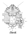
- Fig.1 is a vertical sectional side view of the present dispenser;
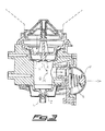
- Fig.2 is a view similar to the preceding one of the dispenser in the detergent delivery phase; and
- Fig.3 is a view similar to the preceding one of the dispenser in the phase of load of the detergent from the container.
-
- With reference to fig.1, there is seen that the present dispenser is provided with a socket A for introducing the detergent container. This socket A may be made in various known ways, e.g. threaded, bayonet-like, snap-in, etc.
- The container (indicated by the dashed lines) has a spring-loaded sliding plug B, integral with an internal valve C which closes some openings D formed on top of the container. When the container is placed on the dispenser, a peg F located at the center of socket A pushes upward plug B and valve C thus allowing the downflow by gravity of the detergent through openings D.
- The detergent first passes through a ring of holes E and fills the space between socket A and a first membrane M which is substantially U-shaped and provided with a central bore closed by a conical shutter N, as better shown in the enlarged detail. The membrane M and shutter N together act as inlet valve to the underlying chamber G which communicates through a duct H with a small pump P located on the front of the dispenser.
- A return spring S is arranged inside pump P, which is operated through a button T whose travel is defined by an adjustable stop R. In practice, member R may be mounted on button T in two or more different positions, so as to change the travel of button T and therefore the amount of dispensed detergent.
- Through a ring of holes X formed in the bottom of chamber G, the detergent fills the space between chamber G and a second membrane V which is substantially U-shaped and provided with a central bore closed by a conical shutter Z, as better shown in the enlarged detail. The membrane V and shutter Z together act as a detergent outlet valve, same as the inlet valve.
- In the light of the above description and with further reference to figures 2 and 3 (where button T has been omitted) the operation of the present dispenser is readily understood.
- When pump P is pushed by overcoming the resistance of spring S, the detergent contained in chamber G can not flow upward to the container because the top membrane M is abutting against shutter N. The pressure created in the chamber therefore causes the deformation of the bottom membrane V, in particular at its thinner horizontal portion W. As a consequence, membrane V moves away from shutter Z and the detergent is dispensed through a small cylinder U acting as delivery nozzle.
- Once the pre-established amount of detergent has been dispensed and the pressure in chamber G has decreased, membrane V elastically returns to its rest position of fig.1. During this return movement the top internal edge of the small cylinder U abuts against the conical surface of shutter Z (see detail of fig. 1). In this way the residual film of detergent possibly remaining on shutter Z is cut and a perfect tightness is achieved without risk of dripping. It should be noted that, in order to provide a greater effectiveness to this cutting and sealing action, the central portion of the membrane is thicker so as to have a greater rigidity.
- The return motion of pump P under the action of spring S causes a vacuum in chamber G, in which however the air can not enter from outside since the bottom membrane V, and in particular cylinder U, abuts against shutter Z. As a consequence, it is the top membrane M, in particular at its thinner horizontal portion L, which is deformed and moves away from shutter N thus allowing the inflow of detergent through the bore formed in the central portion K.
- Same as described above, also in this case membrane M elastically returns to the rest position, with the central portion K abutting against the conical surface of shutter N (see detail of fig.1) thus achieving a perfect seal.
- In practice the two one-way valves operate in the same manner and are different only in some dimensional detail and in the material of which they are preferably made. Some dimensions of a working prototype built by the applicant are indicated hereunder for exemplificatory purposes.
- More specifically, both the top shutter N and the bottom shutter Z have a conicity of 50°, while the corresponding bores which they enter have a diameter of 7 mm and 6 mm respectively. Furthermore, the two membranes are obviously different for the presence on the bottom membrane V of nozzle U which extends for 8,5 mm below the horizontal portion W.
- For the rest the two membranes have the same size and thickness, in particular a minimum thickness of 0,4 mm in the horizontal deformation portions L and W, a maximum thickness of 1,3 mm in the central portions K and U abutting on the respective shutters N and Z, and an intermediate thickness of 0,9 mm in the other portions of the membrane.
- A further difference between the two membranes is the material of which they are preferably made, since they operate in two different environments. In fact while the top membrane M is completely immersed in the detergent and therefore more subject to the chemical aggression, the bottom membrane V is in contact with the detergent only on the inner face and is therefore less subject to aggression.
- As a consequence it is preferable to use for the top membrane M a low-density polyethylene (LDPE) which better resists the detergent without excessively swelling. On the other hand it is preferable to use for the bottom membrane V a thermoplastic elastomer (TPE) with an olefinic base, which having a greater elasticity provides a quick closing of the valve upon delivery without allowing the inlet of air from outside.
- It is clear that the above-described and illustrated embodiment of the dispenser according to the invention is just an example susceptible of various modifications. In particular, the shape and size of the membranes and shutters may be somewhat changed according to specific manufacturing needs, even differentiating the inlet valve from the outlet valve.
- Moreover, the materials used for the membranes may be different from those mentioned above, as long as they have adequate properties of elasticity and resistance to the detergent.
Claims (10)
- Dispenser for pasty detergents, including a socket (A) for introducing a detergent container, a chamber (G) in communication with said socket (A) through a one-way detergent inlet valve and with the outside through a one-way outlet valve, a pressure and a vacuum being alternately created in said chamber (G) through a pump (P) provided with a return spring (S), characterized in that each of said one-way inlet and outlet valves consists of a membrane (M; V) made of an elastically deformable material and provided with a bore, and of a corresponding conical shutter (N; Z) suitable to close said bore.
- Dispenser for pasty detergents according to claim 1, characterized in that the elastic membrane (M; Z) is substantially U-shaped and the bore is formed in a central portion (K; U) having a rigidity greater than the rest of the membrane.
- Dispenser for pasty detergents according to claim 1 or 2, characterized in that the membrane (V) of the outlet valve is provided with a small cylinder (U) acting as delivery nozzle and extending below the horizontal portion (W) of said membrane.
- Dispenser for pasty detergents according to one or more of the preceding claims, characterized in that the membrane (M; V) has a minimum thickness in the horizontal portions (L; W) of a value equal to about 1/3 of the thickness in the central portions (K; U) abutting on the respective shutters (N; Z) and equal to about 1/2 of the thickness in the other portions of the membrane.
- Dispenser for pasty detergents according to the preceding claim, characterized in that the thickness in the horizontal portions (L; W) is 0,4 mm, the thickness in the central portions (K; U) is 1,3 mm and the thickness in the other portions of the membrane is 0,9 mm.
- Dispenser for pasty detergents according to one or more of the preceding claims, characterized in that the conical shutter (N; Z) has a conicity of 50°.
- Dispenser for pasty detergents according to one or more of the preceding claims, characterized in that the membrane (M) of the inlet valve is made of low-density polyethylene.
- Dispenser for pasty detergents according to one or more of the preceding claims, characterized in that the membrane (V) of the outlet valve is made of thermoplastic elastomer with an olefinic base.
- Dispenser for pasty detergents according to one or more of the preceding claims, characterized in that the pump (P) is operated by the user through a button (T) whose travel is adjustable.
- Dispenser for pasty detergents according to the preceding claim, characterized in that the adjustment of the travel of the button (T) is achieved through a stop (R) which can be mounted on said button (T) in two or more different positions.
Priority Applications (6)
| Application Number | Priority Date | Filing Date | Title |
|---|---|---|---|
| DK01830175T DK1243217T3 (en) | 2001-03-14 | 2001-03-14 | Dispensers for doughy cleaners, especially in the form of gel with microspheres |
| ES01830175T ES2220699T3 (en) | 2001-03-14 | 2001-03-14 | DISPENSER OF PASTRY DETERGENTS, PARTICULARLY IN GEL FORM WITH MICROSPHERES. |
| DE60103730T DE60103730T2 (en) | 2001-03-14 | 2001-03-14 | Dispensers for paste-form detergents, in particular gel with microspheres |
| SI200130106T SI1243217T1 (en) | 2001-03-14 | 2001-03-14 | Dispenser for pasty detergents, particularly in the form of gel with microspheres |
| AT01830175T ATE268559T1 (en) | 2001-03-14 | 2001-03-14 | DISPENSER FOR PASTE CLEANING PRODUCTS, ESPECIALLY GEL WITH MICROSPHERES |
| EP01830175A EP1243217B1 (en) | 2001-03-14 | 2001-03-14 | Dispenser for pasty detergents, particularly in the form of gel with microspheres |
Applications Claiming Priority (1)
| Application Number | Priority Date | Filing Date | Title |
|---|---|---|---|
| EP01830175A EP1243217B1 (en) | 2001-03-14 | 2001-03-14 | Dispenser for pasty detergents, particularly in the form of gel with microspheres |
Publications (2)
| Publication Number | Publication Date |
|---|---|
| EP1243217A1 true EP1243217A1 (en) | 2002-09-25 |
| EP1243217B1 EP1243217B1 (en) | 2004-06-09 |
Family
ID=8184443
Family Applications (1)
| Application Number | Title | Priority Date | Filing Date |
|---|---|---|---|
| EP01830175A Expired - Lifetime EP1243217B1 (en) | 2001-03-14 | 2001-03-14 | Dispenser for pasty detergents, particularly in the form of gel with microspheres |
Country Status (6)
| Country | Link |
|---|---|
| EP (1) | EP1243217B1 (en) |
| AT (1) | ATE268559T1 (en) |
| DE (1) | DE60103730T2 (en) |
| DK (1) | DK1243217T3 (en) |
| ES (1) | ES2220699T3 (en) |
| SI (1) | SI1243217T1 (en) |
Citations (8)
| Publication number | Priority date | Publication date | Assignee | Title |
|---|---|---|---|---|
| CH285438A (en) * | 1948-07-16 | 1952-09-15 | Churchill Henry Winston S | Apparatus for dispensing pasty and liquid substances. |
| CH375860A (en) * | 1960-03-01 | 1964-03-15 | Hebeisen Alfred | Device for dispensing liquid soap in portions |
| US3211340A (en) * | 1963-04-23 | 1965-10-12 | Waldo H Zander | Dispensing device |
| US3288332A (en) * | 1964-06-22 | 1966-11-29 | Zyma Sa | Liquid product distributor |
| GB1261815A (en) | 1968-09-03 | 1972-01-26 | Handtmann Metallguss Albert | Fluid dispenser |
| US3838985A (en) | 1972-08-07 | 1974-10-01 | Texas Instruments Inc | Composite three layer metal thermostat |
| DE2341259A1 (en) * | 1973-08-16 | 1975-03-06 | Gss Ges Fuer Sanitaere Spender | Dispenser for liquid soap supplied in non-returnable container - has inward projections to match shaped container and large openings in back panel |
| US6092695A (en) * | 1992-05-11 | 2000-07-25 | Cytologix Corporation | Interchangeable liquid dispensing cartridge pump |
-
2001
- 2001-03-14 DE DE60103730T patent/DE60103730T2/en not_active Expired - Lifetime
- 2001-03-14 EP EP01830175A patent/EP1243217B1/en not_active Expired - Lifetime
- 2001-03-14 DK DK01830175T patent/DK1243217T3/en active
- 2001-03-14 ES ES01830175T patent/ES2220699T3/en not_active Expired - Lifetime
- 2001-03-14 AT AT01830175T patent/ATE268559T1/en active
- 2001-03-14 SI SI200130106T patent/SI1243217T1/en unknown
Patent Citations (8)
| Publication number | Priority date | Publication date | Assignee | Title |
|---|---|---|---|---|
| CH285438A (en) * | 1948-07-16 | 1952-09-15 | Churchill Henry Winston S | Apparatus for dispensing pasty and liquid substances. |
| CH375860A (en) * | 1960-03-01 | 1964-03-15 | Hebeisen Alfred | Device for dispensing liquid soap in portions |
| US3211340A (en) * | 1963-04-23 | 1965-10-12 | Waldo H Zander | Dispensing device |
| US3288332A (en) * | 1964-06-22 | 1966-11-29 | Zyma Sa | Liquid product distributor |
| GB1261815A (en) | 1968-09-03 | 1972-01-26 | Handtmann Metallguss Albert | Fluid dispenser |
| US3838985A (en) | 1972-08-07 | 1974-10-01 | Texas Instruments Inc | Composite three layer metal thermostat |
| DE2341259A1 (en) * | 1973-08-16 | 1975-03-06 | Gss Ges Fuer Sanitaere Spender | Dispenser for liquid soap supplied in non-returnable container - has inward projections to match shaped container and large openings in back panel |
| US6092695A (en) * | 1992-05-11 | 2000-07-25 | Cytologix Corporation | Interchangeable liquid dispensing cartridge pump |
Also Published As
| Publication number | Publication date |
|---|---|
| DK1243217T3 (en) | 2004-10-18 |
| DE60103730D1 (en) | 2004-07-15 |
| ATE268559T1 (en) | 2004-06-15 |
| EP1243217B1 (en) | 2004-06-09 |
| SI1243217T1 (en) | 2004-08-31 |
| ES2220699T3 (en) | 2004-12-16 |
| DE60103730T2 (en) | 2005-06-16 |
Similar Documents
| Publication | Publication Date | Title |
|---|---|---|
| CA1256073A (en) | Wall mounted soap dispenser | |
| US9089860B2 (en) | Bifurcated foam pump, dispensers and refill units | |
| US8413844B2 (en) | Fluid container having an additive dispensing system | |
| US7059501B2 (en) | Valve mechanism for tube-type fluid container | |
| AU2001268841B2 (en) | Pump for dispensing flowable material | |
| US7721918B1 (en) | Automatic dispensing cap for squeezable bottle | |
| EP0052590B1 (en) | Device for dispensing metered quantities of fluid from a container | |
| US5114048A (en) | Faucet assembly having integral liquid product dispenser | |
| GB2380470A (en) | Liquid dispenser for dispensing foam | |
| JPH0364122B2 (en) | ||
| EP1461284B1 (en) | Dispensing faucet | |
| US5842609A (en) | Personal hygiene liquids dispenser | |
| CA2256518A1 (en) | Liquid dispenser with seat for valve skirt | |
| WO2016102598A1 (en) | Dispensers and methods for using the same | |
| US4662195A (en) | Wall-mounted soap dispenser | |
| US20040251444A1 (en) | Valve | |
| US20220314252A1 (en) | Trigger sprayer assembly with dual valve system | |
| US5332129A (en) | Soap dispenser assembly | |
| US11096551B2 (en) | Foam dispensing cleaning tool | |
| EP1243217B1 (en) | Dispenser for pasty detergents, particularly in the form of gel with microspheres | |
| KR0119429Y1 (en) | Soap dispenser | |
| WO2019129461A1 (en) | Dispenser for liquid detergents | |
| CN113543890A (en) | Bidirectional water pump for consuming residual liquid | |
| KR200211163Y1 (en) | Dispenser of a neutral | |
| MXPA98007981A (en) | Pump spit that has a go valve |
Legal Events
| Date | Code | Title | Description |
|---|---|---|---|
| PUAI | Public reference made under article 153(3) epc to a published international application that has entered the european phase |
Free format text: ORIGINAL CODE: 0009012 |
|
| AK | Designated contracting states |
Kind code of ref document: A1 Designated state(s): AT BE CH CY DE DK ES FI FR GB GR IE IT LI LU MC NL PT SE TR |
|
| AX | Request for extension of the european patent |
Free format text: AL;LT;LV;MK;RO;SI |
|
| 17P | Request for examination filed |
Effective date: 20030131 |
|
| AKX | Designation fees paid |
Designated state(s): AT BE CH CY DE DK ES FI FR GB GR IE IT LI LU MC NL PT SE TR |
|
| AXX | Extension fees paid |
Extension state: SI Payment date: 20030131 |
|
| 17Q | First examination report despatched |
Effective date: 20030703 |
|
| GRAP | Despatch of communication of intention to grant a patent |
Free format text: ORIGINAL CODE: EPIDOSNIGR1 |
|
| GRAS | Grant fee paid |
Free format text: ORIGINAL CODE: EPIDOSNIGR3 |
|
| GRAA | (expected) grant |
Free format text: ORIGINAL CODE: 0009210 |
|
| RAP1 | Party data changed (applicant data changed or rights of an application transferred) |
Owner name: QTS S.R.L. |
|
| AK | Designated contracting states |
Kind code of ref document: B1 Designated state(s): AT BE CH CY DE DK ES FI FR GB GR IE IT LI LU MC NL PT SE TR |
|
| AX | Request for extension of the european patent |
Extension state: SI |
|
| PG25 | Lapsed in a contracting state [announced via postgrant information from national office to epo] |
Ref country code: LI Free format text: LAPSE BECAUSE OF FAILURE TO SUBMIT A TRANSLATION OF THE DESCRIPTION OR TO PAY THE FEE WITHIN THE PRESCRIBED TIME-LIMIT Effective date: 20040609 Ref country code: TR Free format text: LAPSE BECAUSE OF FAILURE TO SUBMIT A TRANSLATION OF THE DESCRIPTION OR TO PAY THE FEE WITHIN THE PRESCRIBED TIME-LIMIT Effective date: 20040609 Ref country code: CH Free format text: LAPSE BECAUSE OF FAILURE TO SUBMIT A TRANSLATION OF THE DESCRIPTION OR TO PAY THE FEE WITHIN THE PRESCRIBED TIME-LIMIT Effective date: 20040609 Ref country code: FI Free format text: LAPSE BECAUSE OF FAILURE TO SUBMIT A TRANSLATION OF THE DESCRIPTION OR TO PAY THE FEE WITHIN THE PRESCRIBED TIME-LIMIT Effective date: 20040609 |
|
| REG | Reference to a national code |
Ref country code: GB Ref legal event code: FG4D |
|
| REG | Reference to a national code |
Ref country code: CH Ref legal event code: EP |
|
| REF | Corresponds to: |
Ref document number: 60103730 Country of ref document: DE Date of ref document: 20040715 Kind code of ref document: P |
|
| REG | Reference to a national code |
Ref country code: SE Ref legal event code: TRGR |
|
| REG | Reference to a national code |
Ref country code: IE Ref legal event code: FG4D |
|
| REG | Reference to a national code |
Ref country code: DK Ref legal event code: T3 |
|
| REG | Reference to a national code |
Ref country code: GR Ref legal event code: EP Ref document number: 20040402908 Country of ref document: GR |
|
| REG | Reference to a national code |
Ref country code: CH Ref legal event code: PL |
|
| REG | Reference to a national code |
Ref country code: ES Ref legal event code: FG2A Ref document number: 2220699 Country of ref document: ES Kind code of ref document: T3 |
|
| REG | Reference to a national code |
Ref country code: SI Ref legal event code: IF |
|
| PGFP | Annual fee paid to national office [announced via postgrant information from national office to epo] |
Ref country code: IE Payment date: 20050114 Year of fee payment: 5 |
|
| ET | Fr: translation filed | ||
| PG25 | Lapsed in a contracting state [announced via postgrant information from national office to epo] |
Ref country code: LU Free format text: LAPSE BECAUSE OF NON-PAYMENT OF DUE FEES Effective date: 20050314 Ref country code: CY Free format text: LAPSE BECAUSE OF FAILURE TO SUBMIT A TRANSLATION OF THE DESCRIPTION OR TO PAY THE FEE WITHIN THE PRESCRIBED TIME-LIMIT Effective date: 20050314 |
|
| PG25 | Lapsed in a contracting state [announced via postgrant information from national office to epo] |
Ref country code: MC Free format text: LAPSE BECAUSE OF NON-PAYMENT OF DUE FEES Effective date: 20050331 |
|
| PLBE | No opposition filed within time limit |
Free format text: ORIGINAL CODE: 0009261 |
|
| STAA | Information on the status of an ep patent application or granted ep patent |
Free format text: STATUS: NO OPPOSITION FILED WITHIN TIME LIMIT |
|
| 26N | No opposition filed |
Effective date: 20050310 |
|
| PG25 | Lapsed in a contracting state [announced via postgrant information from national office to epo] |
Ref country code: IE Free format text: LAPSE BECAUSE OF NON-PAYMENT OF DUE FEES Effective date: 20060314 |
|
| REG | Reference to a national code |
Ref country code: IE Ref legal event code: MM4A |
|
| PG25 | Lapsed in a contracting state [announced via postgrant information from national office to epo] |
Ref country code: PT Free format text: LAPSE BECAUSE OF NON-PAYMENT OF DUE FEES Effective date: 20041109 |
|
| PGFP | Annual fee paid to national office [announced via postgrant information from national office to epo] |
Ref country code: BE Payment date: 20080430 Year of fee payment: 8 |
|
| PGFP | Annual fee paid to national office [announced via postgrant information from national office to epo] |
Ref country code: GR Payment date: 20080326 Year of fee payment: 8 |
|
| BERE | Be: lapsed |
Owner name: *QTS S.R.L. Effective date: 20090331 |
|
| REG | Reference to a national code |
Ref country code: SI Ref legal event code: KO00 Effective date: 20091030 |
|
| PG25 | Lapsed in a contracting state [announced via postgrant information from national office to epo] |
Ref country code: BE Free format text: LAPSE BECAUSE OF NON-PAYMENT OF DUE FEES Effective date: 20090331 |
|
| PG25 | Lapsed in a contracting state [announced via postgrant information from national office to epo] |
Ref country code: GR Free format text: LAPSE BECAUSE OF NON-PAYMENT OF DUE FEES Effective date: 20091002 |
|
| PGFP | Annual fee paid to national office [announced via postgrant information from national office to epo] |
Ref country code: AT Payment date: 20110314 Year of fee payment: 11 |
|
| PGFP | Annual fee paid to national office [announced via postgrant information from national office to epo] |
Ref country code: ES Payment date: 20110325 Year of fee payment: 11 |
|
| PGFP | Annual fee paid to national office [announced via postgrant information from national office to epo] |
Ref country code: FR Payment date: 20120403 Year of fee payment: 12 |
|
| PGFP | Annual fee paid to national office [announced via postgrant information from national office to epo] |
Ref country code: DE Payment date: 20120323 Year of fee payment: 12 |
|
| PGFP | Annual fee paid to national office [announced via postgrant information from national office to epo] |
Ref country code: GB Payment date: 20120322 Year of fee payment: 12 Ref country code: DK Payment date: 20120322 Year of fee payment: 12 Ref country code: SE Payment date: 20120322 Year of fee payment: 12 Ref country code: IT Payment date: 20120306 Year of fee payment: 12 |
|
| PGFP | Annual fee paid to national office [announced via postgrant information from national office to epo] |
Ref country code: NL Payment date: 20120327 Year of fee payment: 12 |
|
| REG | Reference to a national code |
Ref country code: AT Ref legal event code: MM01 Ref document number: 268559 Country of ref document: AT Kind code of ref document: T Effective date: 20120314 |
|
| PG25 | Lapsed in a contracting state [announced via postgrant information from national office to epo] |
Ref country code: AT Free format text: LAPSE BECAUSE OF NON-PAYMENT OF DUE FEES Effective date: 20120314 |
|
| REG | Reference to a national code |
Ref country code: ES Ref legal event code: FD2A Effective date: 20130710 |
|
| PG25 | Lapsed in a contracting state [announced via postgrant information from national office to epo] |
Ref country code: ES Free format text: LAPSE BECAUSE OF NON-PAYMENT OF DUE FEES Effective date: 20120315 |
|
| REG | Reference to a national code |
Ref country code: DE Ref legal event code: R082 Ref document number: 60103730 Country of ref document: DE Representative=s name: MAI DOERR BESIER PATENTANWAELTE, DE |
|
| REG | Reference to a national code |
Ref country code: NL Ref legal event code: V1 Effective date: 20131001 |
|
| REG | Reference to a national code |
Effective date: 20130331 Ref country code: DK Ref legal event code: EBP |
|
| REG | Reference to a national code |
Ref country code: SE Ref legal event code: EUG |
|
| PG25 | Lapsed in a contracting state [announced via postgrant information from national office to epo] |
Ref country code: SE Free format text: LAPSE BECAUSE OF NON-PAYMENT OF DUE FEES Effective date: 20130315 |
|
| GBPC | Gb: european patent ceased through non-payment of renewal fee |
Effective date: 20130314 |
|
| REG | Reference to a national code |
Ref country code: FR Ref legal event code: ST Effective date: 20131129 |
|
| REG | Reference to a national code |
Ref country code: DE Ref legal event code: R119 Ref document number: 60103730 Country of ref document: DE Effective date: 20131001 |
|
| PG25 | Lapsed in a contracting state [announced via postgrant information from national office to epo] |
Ref country code: DE Free format text: LAPSE BECAUSE OF NON-PAYMENT OF DUE FEES Effective date: 20131001 Ref country code: FR Free format text: LAPSE BECAUSE OF NON-PAYMENT OF DUE FEES Effective date: 20130402 Ref country code: GB Free format text: LAPSE BECAUSE OF NON-PAYMENT OF DUE FEES Effective date: 20130314 |
|
| PG25 | Lapsed in a contracting state [announced via postgrant information from national office to epo] |
Ref country code: NL Free format text: LAPSE BECAUSE OF NON-PAYMENT OF DUE FEES Effective date: 20131001 Ref country code: IT Free format text: LAPSE BECAUSE OF NON-PAYMENT OF DUE FEES Effective date: 20130314 |
|
| PG25 | Lapsed in a contracting state [announced via postgrant information from national office to epo] |
Ref country code: DK Free format text: LAPSE BECAUSE OF NON-PAYMENT OF DUE FEES Effective date: 20130331 |