EP1242639B1 - Equipment for the even feed of pulverous material to a concentrate burner of suspension smelting furnace - Google Patents
Equipment for the even feed of pulverous material to a concentrate burner of suspension smelting furnace Download PDFInfo
- Publication number
- EP1242639B1 EP1242639B1 EP20000927279 EP00927279A EP1242639B1 EP 1242639 B1 EP1242639 B1 EP 1242639B1 EP 20000927279 EP20000927279 EP 20000927279 EP 00927279 A EP00927279 A EP 00927279A EP 1242639 B1 EP1242639 B1 EP 1242639B1
- Authority
- EP
- European Patent Office
- Prior art keywords
- concentrate
- feed
- burner
- discharge channel
- feed pipe
- Prior art date
- Legal status (The legal status is an assumption and is not a legal conclusion. Google has not performed a legal analysis and makes no representation as to the accuracy of the status listed.)
- Expired - Lifetime
Links
Images


Classifications
-
- C—CHEMISTRY; METALLURGY
- C22—METALLURGY; FERROUS OR NON-FERROUS ALLOYS; TREATMENT OF ALLOYS OR NON-FERROUS METALS
- C22B—PRODUCTION AND REFINING OF METALS; PRETREATMENT OF RAW MATERIALS
- C22B5/00—General methods of reducing to metals
- C22B5/02—Dry methods smelting of sulfides or formation of mattes
- C22B5/12—Dry methods smelting of sulfides or formation of mattes by gases
- C22B5/14—Dry methods smelting of sulfides or formation of mattes by gases fluidised material
-
- F—MECHANICAL ENGINEERING; LIGHTING; HEATING; WEAPONS; BLASTING
- F27—FURNACES; KILNS; OVENS; RETORTS
- F27B—FURNACES, KILNS, OVENS, OR RETORTS IN GENERAL; OPEN SINTERING OR LIKE APPARATUS
- F27B3/00—Hearth-type furnaces, e.g. of reverberatory type; Tank furnaces
- F27B3/10—Details, accessories, or equipment peculiar to hearth-type furnaces
- F27B3/20—Arrangements of heating devices
- F27B3/205—Burners
-
- C—CHEMISTRY; METALLURGY
- C22—METALLURGY; FERROUS OR NON-FERROUS ALLOYS; TREATMENT OF ALLOYS OR NON-FERROUS METALS
- C22B—PRODUCTION AND REFINING OF METALS; PRETREATMENT OF RAW MATERIALS
- C22B15/00—Obtaining copper
- C22B15/0026—Pyrometallurgy
- C22B15/0028—Smelting or converting
- C22B15/0047—Smelting or converting flash smelting or converting
-
- F—MECHANICAL ENGINEERING; LIGHTING; HEATING; WEAPONS; BLASTING
- F27—FURNACES; KILNS; OVENS; RETORTS
- F27B—FURNACES, KILNS, OVENS, OR RETORTS IN GENERAL; OPEN SINTERING OR LIKE APPARATUS
- F27B3/00—Hearth-type furnaces, e.g. of reverberatory type; Tank furnaces
- F27B3/10—Details, accessories, or equipment peculiar to hearth-type furnaces
- F27B3/18—Arrangements of devices for charging
-
- F—MECHANICAL ENGINEERING; LIGHTING; HEATING; WEAPONS; BLASTING
- F27—FURNACES; KILNS; OVENS; RETORTS
- F27D—DETAILS OR ACCESSORIES OF FURNACES, KILNS, OVENS, OR RETORTS, IN SO FAR AS THEY ARE OF KINDS OCCURRING IN MORE THAN ONE KIND OF FURNACE
- F27D3/00—Charging; Discharging; Manipulation of charge
- F27D3/0033—Charging; Discharging; Manipulation of charge charging of particulate material
-
- F—MECHANICAL ENGINEERING; LIGHTING; HEATING; WEAPONS; BLASTING
- F27—FURNACES; KILNS; OVENS; RETORTS
- F27D—DETAILS OR ACCESSORIES OF FURNACES, KILNS, OVENS, OR RETORTS, IN SO FAR AS THEY ARE OF KINDS OCCURRING IN MORE THAN ONE KIND OF FURNACE
- F27D3/00—Charging; Discharging; Manipulation of charge
- F27D2003/0034—Means for moving, conveying, transporting the charge in the furnace or in the charging facilities
- F27D2003/0038—Means for moving, conveying, transporting the charge in the furnace or in the charging facilities comprising shakers
-
- F—MECHANICAL ENGINEERING; LIGHTING; HEATING; WEAPONS; BLASTING
- F27—FURNACES; KILNS; OVENS; RETORTS
- F27D—DETAILS OR ACCESSORIES OF FURNACES, KILNS, OVENS, OR RETORTS, IN SO FAR AS THEY ARE OF KINDS OCCURRING IN MORE THAN ONE KIND OF FURNACE
- F27D3/00—Charging; Discharging; Manipulation of charge
- F27D3/10—Charging directly from hoppers or shoots
Definitions
- This invention relates to equipment for the feed of pulverous material to a concentrate burner of a suspension smelting furnace, which enables the feed of solid finely divided material into the furnace to be distributed evenly in the concentrate burner.
- a vibrating feeder is located between the raw material conveyor and the actual burner, and the concentrate burner feed pipes are equipped with blades for dividing the material.
- the feed of pulverous material such as concentrate, flux and flue dust takes place via the concentrate burner situated on top of the reaction shaft of the furnace.
- concentrate will be used hereafter in the text to mean all the pulverous material fed into the furnace via the concentrate burner. It is extremely important for the successful operation of the concentrate burner that the concentrate and the process air are mixed evenly as they are discharged from the burner into the reaction space i.e. the upper section of the reaction shaft of the suspension smelting furnace.
- the result is on the one hand an area of under-reacted concentrate where the concentrate is above the targeted process-air/concentrate ratio and, on the other hand, an area of over-reacted concentrate where the concentrate is below the targeted process-air/concentrate ratio, whereby a large amount of magnetite is produced as from the reactions. Magnetite is slow to dissolve and impairs the quality of the slag produced so that it raises the viscosity of said slag, and the high viscosity in turn slows down the separation of matte and slag in the lower furnace.
- the concentrate is brought to the concentrate burner from the concentrate feed silo mainly by redler or scraper conveyor, from where the raw material flow for discharge is taken first to the concentrate burner hopper and from there along the concentrate feed pipes to the actual concentrate burner itself.
- the equipment is constructed in accordance with the spaces being used, so the conveyor and concentrate pipes may be at a 90° angle to each other, whereby in changing the direction of flow in the concentrate burner hopper, the concentrate, which is in a slightly fluidized state, behaves like a liquid, and the flow and especially the distribution of the concentrate in the cross-sectional area of the concentrate pipe is uneven, further weakening the distribution of the concentrate in the burner.
- the vibrating feeder belonging to the concentrate burner feed equipment is located in relation to the actual concentrate burner so that the flow of concentrate coming from the feeder is perpendicular to the vertical axis of the burner, whereby the concentrate flow can be distributed evenly after the feeder in the desired amount.
- changing the direction of the concentrate flow was considered a drawback above, in this case it is not, as the concentrate pipes positioned after the vibrating feeder are equipped with partitions, which divide the concentrate evenly over the whole cross-sectional area of the pipes. The divide is further ensured by making small spreaders in the feeder, which improve the exact dispersion in certain points.
- the concentrate distribution achieved by the vibrating feeder is preserved by dividing the feed pipes from the vibrating feeder to the concentrate burner with partitions, or blades.
- the feed equipment according to the present invention works excellently in the case of a single feeder, evening out the flow of concentrate over both time and place. If, however, the arrangement includes two concentrate conveyors and it is wished to operate them asynchronously, the result is once again an uneven distribution of raw material. This situation can be resolved in two ways, depending on whether asynchronous feeding is a regular or rare occurrence.
- Figure 1 shows a flash-smelting furnace 1, into which pulverous solid material is fed via a concentrate burner 2.
- the concentrate is transferred from a tank 3 on a conveyor 4 to the upper section of a discharge channel 5, so that the material falls as a continuous flow through said channel 5 to the upper section 7 of reaction shaft 6 of the furnace 1.
- Reaction gas is routed via gas feed elements 8 around the concentrate channel parallel to the reaction shaft into its upper part.
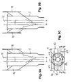
- FIG. 2 shows in more detail an equipment for the even distribution of concentrate to the burner according to the present invention where the feed of both concentrate and reaction gas occurs from two directions.
- the concentrate is taken by conveyor to the concentrate tanks 3, which are connected at its lower section to vibrating feeders 9.
- the vibrating feeders are further equipped with spreaders to ensure the even distribution of the concentrate, but the spreaders are not shown in the drawing.
- the vibrating feeders in turn are connected to concentrate feed pipes 10, from where the concentrate flows down into the discharge channel 5.
- a concentrate distributor 11 is located in the centre of the discharge channel.
- the lower section of a sliding surface 12 is perforated with holes through which air fed horizontally spreads the concentrate flow upwards. Since the concentrate distributor is known in the prior art, the equipment related to it is not shown in more detail.
- the gas feed arrangement 13 for the concentrate burner is also bipartite in its upper section and combines at the base into an annular feed device 14 around the concentrate discharge channel 5.
- the burner is made up in its entirety of the reaction gas feed elements, the concentrate feed elements and centrally located concentrate distributor, and if required, extra fuel and/or extra gas feed elements can be placed inside the concentrate distributor.
- Figures 3A and 3B present one way in which the concentrate feed may be evened out, by furnishing the concentrate feed pipes with partitions, when the concentrate feed comes from two feed pipes 10 in opposing directions, into discharge channel 5.
- the feed pipes are furnished with a partition 15, which divides the pipes essentially into two equally large channels 16.
- the partitions inside the discharge channel extend as far as concentrate distributor 11. Partitions, or blades 17, are also made in the discharge channel 5, perpendicularly to the feed pipe partitions.
- the flow of concentrate is divided into the furnace through four segments 18, symmetrical to each other.
- the segments, or sectors may be of different sizes in relation to each other.
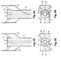
- FIGS 4A and 4B present a feed arrangement where the concentrate feed comes from only one feed pipe.
- the feed pipe 10 is also divided with a partition 15 extending to the concentrate distributor 11.
- the discharge channel 5 is additionally divided by blades 19 also into four segments up to the concentrate burner which blades are in more or less the same direction with the feed pipe partition 15.
- the innermost segments 20 are smaller in cross-section than the outermost segments 21.
- the unused feed pipe partition functions as a continuous partition between the segments.
- the rear of the discharge channel is divided into two by a plate in the same direction as the feed pipe partition 15. Differently sized segments may cause a certain degree of unevenness in the feed distribution, but this solution is generally intended to be a temporary one, and in any case, it offers a better result than the previously used, undivided discharge channel.
- FIGS 5A, 5B and 5C show another alternative according to the present invention, where the concentrate pipes 10 are divided with several partitions.
- the central partitions 15 are positioned radially in the discharge channel to divide the concentrate pipes and the discharge channel into two sectors as in the earlier solutions.
- the outer partitions 22 of the concentrate pipes are basically parallel to the central partition 15.
- the blades 23 inside the discharge channel are also mainly parallel to the outer partitions of the concentrate pipes but do not extend to the concentrate distributor 11. They are positioned between the wall of the discharge channel and the concentrate distributor. It is evident that the shape of the blades can be modified somewhat without altering the idea of the invention.
Landscapes
- Engineering & Computer Science (AREA)
- Mechanical Engineering (AREA)
- General Engineering & Computer Science (AREA)
- Chemical & Material Sciences (AREA)
- Manufacturing & Machinery (AREA)
- Materials Engineering (AREA)
- Metallurgy (AREA)
- Organic Chemistry (AREA)
- Manufacture And Refinement Of Metals (AREA)
- Furnace Charging Or Discharging (AREA)
- Crucibles And Fluidized-Bed Furnaces (AREA)
Applications Claiming Priority (3)
| Application Number | Priority Date | Filing Date | Title |
|---|---|---|---|
| FI991226 | 1999-05-31 | ||
| FI991226A FI105828B (fi) | 1999-05-31 | 1999-05-31 | Laitteisto suspensiosulatusuunin rikastepolttimen jauhemaisen materiaalin syötön tasaamiseksi |
| PCT/FI2000/000433 WO2000073519A1 (en) | 1999-05-31 | 2000-05-12 | Equipment for the even feed of pulverous material to a concentrate burner of suspension smelting furnace |
Publications (2)
| Publication Number | Publication Date |
|---|---|
| EP1242639A1 EP1242639A1 (en) | 2002-09-25 |
| EP1242639B1 true EP1242639B1 (en) | 2004-10-27 |
Family
ID=8554765
Family Applications (1)
| Application Number | Title | Priority Date | Filing Date |
|---|---|---|---|
| EP20000927279 Expired - Lifetime EP1242639B1 (en) | 1999-05-31 | 2000-05-12 | Equipment for the even feed of pulverous material to a concentrate burner of suspension smelting furnace |
Country Status (23)
| Country | Link |
|---|---|
| US (1) | US6565799B1 (bg) |
| EP (1) | EP1242639B1 (bg) |
| JP (1) | JP2003500627A (bg) |
| KR (1) | KR100567952B1 (bg) |
| CN (1) | CN1237193C (bg) |
| AR (1) | AR024099A1 (bg) |
| AU (1) | AU775396B2 (bg) |
| BG (1) | BG64395B1 (bg) |
| BR (1) | BR0011079A (bg) |
| CA (1) | CA2374888A1 (bg) |
| DE (1) | DE60015391T2 (bg) |
| EA (1) | EA003004B1 (bg) |
| ES (1) | ES2228516T3 (bg) |
| FI (1) | FI105828B (bg) |
| MX (1) | MXPA01011774A (bg) |
| PE (1) | PE20010105A1 (bg) |
| PL (1) | PL193684B1 (bg) |
| PT (1) | PT1242639E (bg) |
| RO (1) | RO120715B1 (bg) |
| TR (1) | TR200103379T2 (bg) |
| WO (1) | WO2000073519A1 (bg) |
| YU (1) | YU85301A (bg) |
| ZA (1) | ZA200109325B (bg) |
Families Citing this family (15)
| Publication number | Priority date | Publication date | Assignee | Title |
|---|---|---|---|---|
| FI117769B (fi) * | 2004-01-15 | 2007-02-15 | Outokumpu Technology Oyj | Suspensiosulatusuunin syöttöjärjestelmä |
| FI120101B (fi) * | 2007-09-05 | 2009-06-30 | Outotec Oyj | Rikastepoltin |
| AP2010005222A0 (en) | 2007-09-14 | 2010-04-30 | Barrick Gold Corp | Process for recovering platinum group metals usingreductants |
| FI121852B (fi) * | 2009-10-19 | 2011-05-13 | Outotec Oyj | Menetelmä polttoainekaasun syöttämiseksi suspensiosulatusuunin reaktiokuiluun ja rikastepoltin |
| FI122306B (fi) * | 2009-12-11 | 2011-11-30 | Outotec Oyj | Järjestely suspensiosulatusuunin rikastepolttimen jauhemaisen kiintoaineen syötön tasaamiseksi |
| US9103592B2 (en) | 2011-05-06 | 2015-08-11 | Hatch Ltd. | Burner with velocity adjustment for flash smelter |
| FI125166B (en) * | 2013-04-08 | 2015-06-30 | Outotec Oyj | PROCEDURES AND ARRANGEMENTS FOR FEEDING RAW MATERIAL FROM A RAW MATERIAL CONTAINER INTO A OVEN OVEN SPACE |
| WO2014201556A1 (en) | 2013-06-17 | 2014-12-24 | Hatch Ltd. | Feed flow conditioner for particulate feed materials |
| JP6291205B2 (ja) | 2013-10-01 | 2018-03-14 | パンパシフィック・カッパー株式会社 | 原料供給装置及び原料供給方法、並びに自溶炉 |
| FI20155255A (fi) * | 2015-04-08 | 2016-10-09 | Outotec Finland Oy | Poltin |
| BE1023227B1 (fr) | 2015-06-22 | 2017-01-03 | S.A. Lhoist Recherche Et Developpement | Dispositif et procédé de traitement de gaz de fumées |
| CN108680029B (zh) * | 2016-08-04 | 2019-08-02 | 合肥通用机械研究院有限公司 | 一种改进的振动预混型精矿喷嘴 |
| RU2642214C1 (ru) * | 2017-03-14 | 2018-01-24 | Владимир Александрович Трусов | Установка для загрузки шихтовых материалов в индукционную печь для плавки чёрных и цветных металлов |
| CN107957196B (zh) * | 2017-10-31 | 2019-02-15 | 重庆琅博宛冶金材料有限公司 | 一种方便进料的冶炼炉 |
| CN114277214A (zh) * | 2021-12-31 | 2022-04-05 | 四川德胜集团钒钛有限公司 | 一种半钢冶炼炉及炼钢方法 |
Family Cites Families (7)
| Publication number | Priority date | Publication date | Assignee | Title |
|---|---|---|---|---|
| DE2424237A1 (de) | 1974-05-18 | 1975-11-27 | Johannes Dr Ing Wotschke | Rundumbeschickung eines flammenkammerofens mittels einer kegelschurre und drehbeweglicher auslauf-ringschale |
| US4326702A (en) * | 1979-10-22 | 1982-04-27 | Oueneau Paul E | Sprinkler burner for introducing particulate material and a gas into a reactor |
| US4744311A (en) * | 1987-05-27 | 1988-05-17 | Riley Stoker Corporation | System for feeding solid particulate material for combustion in a reactor vessel |
| FI91283C (fi) * | 1991-02-13 | 1997-01-13 | Outokumpu Research Oy | Tapa ja laitteisto pulverimaisen kiintoaineen kuumentamiseksi ja sulattamiseksi sekä siinä olevien haihtuvien aineosasten haihduttamiseksi suspensiosulatusuunissa |
| FI94150C (fi) * | 1992-06-01 | 1995-07-25 | Outokumpu Eng Contract | Tapa ja laite reaktiokaasujen syöttämiseksi sulatusuuniin |
| FI94152C (fi) * | 1992-06-01 | 1995-07-25 | Outokumpu Eng Contract | Tapa ja laite pulverimaisen polttoaineen hapettamiseksi kahdella eri happipitoisuuden omaavalla kaasulla |
| FI98071C (fi) | 1995-05-23 | 1997-04-10 | Outokumpu Eng Contract | Menetelmä ja laitteisto reaktiokaasun ja kiintoaineen syöttämiseksi |
-
1999
- 1999-05-31 FI FI991226A patent/FI105828B/fi active
-
2000
- 2000-05-12 PL PL00351867A patent/PL193684B1/pl unknown
- 2000-05-12 ES ES00927279T patent/ES2228516T3/es not_active Expired - Lifetime
- 2000-05-12 RO ROA200101251A patent/RO120715B1/ro unknown
- 2000-05-12 WO PCT/FI2000/000433 patent/WO2000073519A1/en active IP Right Grant
- 2000-05-12 EA EA200101269A patent/EA003004B1/ru not_active IP Right Cessation
- 2000-05-12 KR KR1020017015336A patent/KR100567952B1/ko not_active IP Right Cessation
- 2000-05-12 TR TR2001/03379T patent/TR200103379T2/xx unknown
- 2000-05-12 JP JP2001500006A patent/JP2003500627A/ja active Pending
- 2000-05-12 CN CNB008083533A patent/CN1237193C/zh not_active Expired - Fee Related
- 2000-05-12 CA CA002374888A patent/CA2374888A1/en not_active Abandoned
- 2000-05-12 MX MXPA01011774A patent/MXPA01011774A/es unknown
- 2000-05-12 EP EP20000927279 patent/EP1242639B1/en not_active Expired - Lifetime
- 2000-05-12 AU AU45713/00A patent/AU775396B2/en not_active Ceased
- 2000-05-12 US US09/979,450 patent/US6565799B1/en not_active Expired - Fee Related
- 2000-05-12 DE DE60015391T patent/DE60015391T2/de not_active Expired - Fee Related
- 2000-05-12 YU YU85301A patent/YU85301A/sh unknown
- 2000-05-12 BR BR0011079-5A patent/BR0011079A/pt active Search and Examination
- 2000-05-12 PT PT00927279T patent/PT1242639E/pt unknown
- 2000-05-24 AR ARP000102548A patent/AR024099A1/es unknown
- 2000-05-25 PE PE2000000500A patent/PE20010105A1/es not_active Application Discontinuation
-
2001
- 2001-11-13 ZA ZA200109325A patent/ZA200109325B/xx unknown
- 2001-11-21 BG BG106131A patent/BG64395B1/bg unknown
Also Published As
| Publication number | Publication date |
|---|---|
| EA200101269A1 (ru) | 2002-04-25 |
| EA003004B1 (ru) | 2002-12-26 |
| BG106131A (bg) | 2002-05-31 |
| CN1237193C (zh) | 2006-01-18 |
| BR0011079A (pt) | 2002-03-19 |
| DE60015391T2 (de) | 2006-02-09 |
| FI991226A0 (fi) | 1999-05-31 |
| WO2000073519A1 (en) | 2000-12-07 |
| DE60015391D1 (de) | 2004-12-02 |
| AR024099A1 (es) | 2002-09-04 |
| AU775396B2 (en) | 2004-07-29 |
| KR100567952B1 (ko) | 2006-04-05 |
| JP2003500627A (ja) | 2003-01-07 |
| ZA200109325B (en) | 2002-08-28 |
| PL351867A1 (en) | 2003-06-30 |
| TR200103379T2 (tr) | 2002-05-21 |
| YU85301A (sh) | 2004-07-15 |
| MXPA01011774A (es) | 2002-04-24 |
| CA2374888A1 (en) | 2000-12-07 |
| KR20020008411A (ko) | 2002-01-30 |
| RO120715B1 (ro) | 2006-06-30 |
| PE20010105A1 (es) | 2001-03-09 |
| CN1353771A (zh) | 2002-06-12 |
| BG64395B1 (bg) | 2004-12-30 |
| PL193684B1 (pl) | 2007-03-30 |
| FI105828B (fi) | 2000-10-13 |
| EP1242639A1 (en) | 2002-09-25 |
| AU4571300A (en) | 2000-12-18 |
| ES2228516T3 (es) | 2005-04-16 |
| PT1242639E (pt) | 2005-02-28 |
| US6565799B1 (en) | 2003-05-20 |
Similar Documents
| Publication | Publication Date | Title |
|---|---|---|
| EP1242639B1 (en) | Equipment for the even feed of pulverous material to a concentrate burner of suspension smelting furnace | |
| CA2780456C (en) | Arrangement for evening out powdery solid matter feed of a concentrate burner of a suspension smelting or suspension converting furnace | |
| CS248703B2 (en) | Apparatus for charging of the loose material with sintering tendency | |
| US1663173A (en) | Process of and apparatus for controlling the movement of masses of solids of various sizes | |
| US3532326A (en) | Device for separately supplying coarse grain and fine grain material to a container such that the material is uniformly distributed in the container | |
| GB2193449A (en) | Air gravity classifier for loose materials | |
| US4203391A (en) | Fluidized bed fuel feeder | |
| KR100641466B1 (ko) | 샤프트 로 | |
| AU2010329750B2 (en) | Arrangement for evening out powdery solid matter feed of a concentrate burner of a suspension smelting or suspension converting furnace | |
| SU739320A1 (ru) | Распределитель шихты загрузочного устройства шахтной печи | |
| CA1111314A (en) | Fluidized bed fuel feeder | |
| SU775578A1 (ru) | Загрузочно-распределительное устройство шахтной печи | |
| KR100778181B1 (ko) | 고정층을 형성하는 방법 및 장치 | |
| KR860001752B1 (ko) | 석탄을 연료로 하는 석회석 소성로 | |
| JP2019211122A (ja) | 炉頂装置 | |
| AU639068B2 (en) | Fluidized bed preliminary reducing furnace for raw material comprising oxide | |
| KR20030054035A (ko) | 소결조업용 배합원료 장입장치 | |
| JPH04110395U (ja) | 噴流層造粒炉 | |
| JPS6029509A (ja) | 焼却炉への焼却物投入方法 |
Legal Events
| Date | Code | Title | Description |
|---|---|---|---|
| PUAI | Public reference made under article 153(3) epc to a published international application that has entered the european phase |
Free format text: ORIGINAL CODE: 0009012 |
|
| 17P | Request for examination filed |
Effective date: 20011129 |
|
| AK | Designated contracting states |
Kind code of ref document: A1 Designated state(s): DE ES PT SE |
|
| GRAP | Despatch of communication of intention to grant a patent |
Free format text: ORIGINAL CODE: EPIDOSNIGR1 |
|
| GRAS | Grant fee paid |
Free format text: ORIGINAL CODE: EPIDOSNIGR3 |
|
| GRAA | (expected) grant |
Free format text: ORIGINAL CODE: 0009210 |
|
| AK | Designated contracting states |
Kind code of ref document: B1 Designated state(s): DE ES PT SE |
|
| REG | Reference to a national code |
Ref country code: IE Ref legal event code: FG4D |
|
| REF | Corresponds to: |
Ref document number: 60015391 Country of ref document: DE Date of ref document: 20041202 Kind code of ref document: P |
|
| REG | Reference to a national code |
Ref country code: SE Ref legal event code: TRGR |
|
| REG | Reference to a national code |
Ref country code: PT Ref legal event code: SC4A Free format text: AVAILABILITY OF NATIONAL TRANSLATION Effective date: 20041229 |
|
| PGFP | Annual fee paid to national office [announced via postgrant information from national office to epo] |
Ref country code: PT Payment date: 20050415 Year of fee payment: 6 |
|
| REG | Reference to a national code |
Ref country code: ES Ref legal event code: FG2A Ref document number: 2228516 Country of ref document: ES Kind code of ref document: T3 |
|
| PLBE | No opposition filed within time limit |
Free format text: ORIGINAL CODE: 0009261 |
|
| STAA | Information on the status of an ep patent application or granted ep patent |
Free format text: STATUS: NO OPPOSITION FILED WITHIN TIME LIMIT |
|
| 26N | No opposition filed |
Effective date: 20050728 |
|
| PG25 | Lapsed in a contracting state [announced via postgrant information from national office to epo] |
Ref country code: PT Free format text: LAPSE BECAUSE OF NON-PAYMENT OF DUE FEES Effective date: 20061113 |
|
| REG | Reference to a national code |
Ref country code: PT Ref legal event code: MM4A Free format text: LAPSE DUE TO NON-PAYMENT OF FEES Effective date: 20061113 |
|
| PGFP | Annual fee paid to national office [announced via postgrant information from national office to epo] |
Ref country code: DE Payment date: 20080425 Year of fee payment: 9 Ref country code: ES Payment date: 20080512 Year of fee payment: 9 |
|
| PGFP | Annual fee paid to national office [announced via postgrant information from national office to epo] |
Ref country code: SE Payment date: 20080421 Year of fee payment: 9 |
|
| PG25 | Lapsed in a contracting state [announced via postgrant information from national office to epo] |
Ref country code: DE Free format text: LAPSE BECAUSE OF NON-PAYMENT OF DUE FEES Effective date: 20091201 |
|
| REG | Reference to a national code |
Ref country code: ES Ref legal event code: FD2A Effective date: 20090513 |
|
| PG25 | Lapsed in a contracting state [announced via postgrant information from national office to epo] |
Ref country code: ES Free format text: LAPSE BECAUSE OF NON-PAYMENT OF DUE FEES Effective date: 20090513 |
|
| PG25 | Lapsed in a contracting state [announced via postgrant information from national office to epo] |
Ref country code: SE Free format text: LAPSE BECAUSE OF NON-PAYMENT OF DUE FEES Effective date: 20090513 |
|
| REG | Reference to a national code |
Ref country code: ES Ref legal event code: FD2A Effective date: 20110714 |
|
| PG25 | Lapsed in a contracting state [announced via postgrant information from national office to epo] |
Ref country code: ES Free format text: LAPSE BECAUSE OF NON-PAYMENT OF DUE FEES Effective date: 20100513 |