EP1242142B1 - Rate adjustable drug delivery system - Google Patents
Rate adjustable drug delivery system Download PDFInfo
- Publication number
- EP1242142B1 EP1242142B1 EP00973406A EP00973406A EP1242142B1 EP 1242142 B1 EP1242142 B1 EP 1242142B1 EP 00973406 A EP00973406 A EP 00973406A EP 00973406 A EP00973406 A EP 00973406A EP 1242142 B1 EP1242142 B1 EP 1242142B1
- Authority
- EP
- European Patent Office
- Prior art keywords
- galvanic
- sources
- iontophoretic
- source
- delivery
- Prior art date
- Legal status (The legal status is an assumption and is not a legal conclusion. Google has not performed a legal analysis and makes no representation as to the accuracy of the status listed.)
- Expired - Lifetime
Links
Images


Classifications
-
- A—HUMAN NECESSITIES
- A61—MEDICAL OR VETERINARY SCIENCE; HYGIENE
- A61N—ELECTROTHERAPY; MAGNETOTHERAPY; RADIATION THERAPY; ULTRASOUND THERAPY
- A61N1/00—Electrotherapy; Circuits therefor
- A61N1/02—Details
- A61N1/04—Electrodes
- A61N1/0404—Electrodes for external use
- A61N1/0408—Use-related aspects
- A61N1/0428—Specially adapted for iontophoresis, e.g. AC, DC or including drug reservoirs
- A61N1/0448—Drug reservoir
-
- A—HUMAN NECESSITIES
- A61—MEDICAL OR VETERINARY SCIENCE; HYGIENE
- A61N—ELECTROTHERAPY; MAGNETOTHERAPY; RADIATION THERAPY; ULTRASOUND THERAPY
- A61N1/00—Electrotherapy; Circuits therefor
- A61N1/02—Details
- A61N1/04—Electrodes
- A61N1/0404—Electrodes for external use
- A61N1/0408—Use-related aspects
- A61N1/0428—Specially adapted for iontophoresis, e.g. AC, DC or including drug reservoirs
- A61N1/0432—Anode and cathode
- A61N1/0436—Material of the electrode
-
- A—HUMAN NECESSITIES
- A61—MEDICAL OR VETERINARY SCIENCE; HYGIENE
- A61N—ELECTROTHERAPY; MAGNETOTHERAPY; RADIATION THERAPY; ULTRASOUND THERAPY
- A61N1/00—Electrotherapy; Circuits therefor
- A61N1/02—Details
- A61N1/04—Electrodes
- A61N1/0404—Electrodes for external use
- A61N1/0408—Use-related aspects
- A61N1/0428—Specially adapted for iontophoresis, e.g. AC, DC or including drug reservoirs
- A61N1/0432—Anode and cathode
- A61N1/044—Shape of the electrode
Definitions
- the present invention concerns transdermal delivery of therapeutic agents by use of an applied electromotive force, commonly known as iontophoresis. More particularly, the invention is directed to a system for iontophoresis that is self contained, quantitatively self limiting, and in which the delivery rate is variable or adjustable.
- the system is contained preferably in a rather small skin worn patch which contains electrodes and a therapeutic agent. When applied to the skin, the system completes a circuit and spontaneously initiates the flow of a galvanic current of measured, limited duration corresponding to the desired amount of therapeutic agent to be delivered.
- the system may be anode or cathode limited.
- ions bearing a positive charge are driven across the skin at the site of an electrolytic electrical system anode, while ions bearing a negative charge are driven across the skin at the site of an electrolytic electrical system cathode.
- the application time and level of current flow (usually reported in units of milliamp minutes) between the anode and cathode is directly correlated to the amount of drug delivered.
- the efficiency of drug delivery in an iontophoretic system can be measured by the proportion of current carried by the drug molecule, relative to the current carried by competing non-medication ions having the same charge as the medication.
- iontophoresis devices are conventionally comprised of two electrodes attached to a patient, each connected via a wire to a microprocessor controlled electrical instrument. Medication is placed under one or both of the electrodes, for delivery into the body as the instrument is activated.
- the instrument is designed to regulate current flow and application time. Examples of such instruments are described in U.S. patents 5,254,081 , and 5,431,625 .
- Power for these devices is usually provided by DC batteries, which when providing power for the microprocessor controlled circuitry allow application of a voltage to the electrodes to create a regulated current flow.
- the automated control of current flow and time is of great advantage, in order to prevent excessive dosages of therapeutic agents from being delivered.
- a significant advantage of a microprocessor controlled iontophoretic system is an ability to adjust electrical current as a function of time, while the system is being used. For example, to administer medication quickly into systemic circulation, an initial high flow rate is desired. However, adjustment to a lower flow rate may be desired afterward for optimal maintenance of a particular plasma medication level.
- wearable iontophoretic systems have been developed in which the electrical circuitry and power supplied are integrated into a single patch. These systems are advantageous in that they do not require external wires, and they are much smaller in size. Examples of such systems can be found in U.S. patents 5,358,483 ; 5,458,569 ; 5,466,217 ; 5, 605, 536 ; and 5,651,768 . However, these systems also have drawbacks. They are relatively inflexible and expensive, owing to the requirements of multiple electronic components, battery power supplies and electrical interconnects.
- Document EP-A-0 893 139 discloses a skin-wearable transdermal iontophoretic therapeutic agent delivery system comprising serially connected electrochemistry cells, and a resistance device and switch connected in parallel with the electrochemistry cells, the electrochemistry cells expiring at different times from each other.
- Power to drive iontophoretic current flow can also be supplied by galvanic means, which utilizes dissimilar anode and cathode materials to produce a spontaneous current flow when they are contacted with the body.
- galvanic means which utilizes dissimilar anode and cathode materials to produce a spontaneous current flow when they are contacted with the body.
- Horstmann in U.S. patent 5, 695, 837 , describes a transdermal therapeutic system which uses series mounted sheet-like galvanic elements as a power source. That device has an ability to either create a constant intensity of current using a high internal resistance element, or create a gradual decreasing current intensity using a low internal resistance element. The low internal resistance, and a decreasing current flow, is caused by a build up of ions into an electrolyte layer of the galvanic element.
- galvanically powered systems Another restriction or limitation of galvanically powered systems is an inability to increase or decrease voltage (and medication delivery) during use.
- the voltage is fixed by the galvanic 1/2 reactions used, and cannot be altered in process. This is a significant disadvantage in circumstances where increasing rate of delivery, such as to administer a bolus of medication, is desired. Accordingly, it would present a great advantage were increased potential available in such a device.
- a primary object of the invention is to provide a galvanically powered iontophoretic device which can provide any desired time voltage profile (and consequently customize the rate profile of medication delivery) using materials which are non-pH reactive in contact with water, and stable when used in the in a manufacturing process.
- a further object of the present invention is to provide an iontophoretic device which can provide any desired time-voltage or delivery profile using circuit components without requiring a microprocessor.
- Another object of the invention is to provide an iontophoretic device capable of maintaining voltage at a stable level for a known charge dosage, afterwards having an automated ability to adjust the voltage downward or upward to at least a second known voltage in rapid fashion, without requiring an integrated microprocessor.
- Still another object of the invention is to provide a galvanically powered system in which the potential level can be made time variable by employing several serially connected galvanic sources of different coulombic capacities in conjunction with parallel connected resistor devices.
- An iontophoretic patch in accordance with the invention includes in its simplest form at least three chambers: a cationic drug chamber, an anionic drug chamber, and an additional galvanic source or cell.
- the system may also have a series of such cells together with one or more parallel connected resistance devices or other components in more complex versions.
- a cationic drug chamber an electrode is contained which includes or is coated with, an electrochemically oxidizable species.
- an electrode is contained which includes or is coated with, an electrochemically reducible species.
- the chambers are separated by a known distance optimally between 0.1 and 2. cm.
- the cationic chamber electrode and the anionic chamber electrode are connected by electrically conductive elements to an additional intermediate electrochemical cell or cells.
- Opposing ends of the electrically conductive elements, which extend to the intermediate cell or cells, are comprised of, or coated with, reductive species if the end opposite is oxidative, or oxidative species if the end opposite is reductive.
- one or more resistor devices are connected in parallel with one or more of the galvanic sources. This assures serial operation of multiple source systems while all sources are operating and provides paths across depleted cells of lesser capacity in the system so that a therapeutic agent can continue to be administered to a lower rate.
- one or more switching devices can be provided in the iontophoretic patch to switch one or more of the intermediate sources or chambers into the circuit or to bypass or shunt one or more galvanic sources as desired.
- a switching device rather than a resister can also be used to by-pass a depleted galvanic source without added circuit resistance if it is desired to provide an initial bolus of therapeutic material, all serially connected sources or cells can be employed for an initial period and one or more configured to deplete and thereby reduce the potential at a later time.
- one or more of the intermediate chambers can be made anode or cathode limited in a manner which causes depletion at a time when the desired bolus of initial material has been delivered.
- Parallel resistors or switches then, provide a conductive path to enable delivery to continue at a lower rate.
- Switching devices can also be employed which shut off the entire galvanic flow in the iontophoretic patch or to switch in additional series connected galvanic sources as by opening by-pass conductor circuits for example.
- galvanic sources can be serially connected in opposed polarity such that a lower capacity source opposes a therapeutic or agent delivery source to initially delay agent delivery until the lower capacity source is depleted.
- the oxidizable species and the reducible species are selected so as to provide a spontaneous galvanic potential and current flow when the iontophoretic patch is in contact with the body.
- An example of a suitable oxidizable species is zinc and a suitable reducible species is silver chloride. While this combination may be advantageous for many applications, it is not meant as a limitation as the scope of the invention but is presented only by way of example.
- the oxidizable species in the cationic drug chamber and one or more intermediate cells become oxidized, while the reducible species in the anionic chamber and intermediate cells become reduced.
- the galvanically induced current will continue to flow until depletion of either the oxidizable or reducible species, whichever is present in limiting amount.
- the relationship between the amount of current flow and the amount of oxidizable or reducible species in limiting supply, is theoretically represented by Faradays constant; one gram equivalent of the limiting reducible or oxidizable species will provide one Faraday (96,487 coulombs) of electricity.
- the iontophoretic patch of this invention will optimally deliver a fixed and known charge in a range between about 0.06 and 60 coulombs, which corresponds to between 0.00000062 and 0.00062 gram equivalent weight of oxidizable or reducible species in limiting supply.
- oxidizable material can be used of known weight and purity; or an oxidizable coating of known amount can be deposited on the surface of an electrically conductive substrate.
- a known amount of molten zinc can be deposited over a wire substrate, to produce an electrode with known oxidizable species content.
- a reducible material of known amount can be deposited on the surface of an electrically conductive substrate.
- a known amount of molten silver chloride can be deposited over a wire substrate, to produce an electrode with known reducible species content.
- a known amount of silver chloride can be generated on the electrode surface by an electrolytic or electroplating process, such as by electrolytic oxidation of a silver wire in the presence of chloride, to produce a coating of silver chloride.
- the preferred approach to preparation of the iontophoretic electrodes of this invention is by screen printing of thin coatings, having known amounts of electroactive materials, over a conductive trace on a flexible substrate. This process yields a controlled dosage galvanic battery, for incorporation into the iontophoretic patch.
- Other circuit elements may also, be created using thin film, screen printing or other such methods in accordance with state-of-the-art techniques.
- an impervious backing material which can be constructed with 3M polyethylene tape #1523, #1526, (available from 3M Corporation, St. Paul, Minnesota) or other occlusive material. Holding the electrodes in place, and attached to the backing material is a cell wall defining layer, which has separated openings to define anode and cathode cell cavities, as well as intermediate chamber cavities.
- the cell wall defining layer can be constructed of 3M #1772 or similar material.
- An absorbent layer is added to each of the cavities defined by the cell wall defining layer, and serves to retain fluid in the cell cavity.
- the absorbent layer can be a material which forms a gel when contacted with aqueous solution such as polyacrylamide, or it can be cotton, gauze, or other hydrophilic material.
- An adhesive layer is used to fix the iontophoretic device to the skin, which can also be comprised of materials such as 3M #1523 or #1526.
- solution containing cation to be delivered is put into the cationic drug chamber, and solution containing anion material is injected into the anionic drug chamber.
- the intermediate chamber is preferably filled with a conductive salt solution, through an access port on either the top or bottom of the device.
- the intermediate chamber can be pre-filled with a salt-containing gel or paste.
- the intermediate chamber or source or sources should not be in contact with the skin.
- the patch is then applied to the portion of the body where drug is to be administered, and adhered to the skin by an adhesive layer on the bottom of the patch and or by an overlaying bandage material. Once contacted with skin, an electrical circuit is completed which allows passage of current and delivery of drug compounds.
- the detailed description of the present invention illustrates the principles of an advanced multi-source, multi-rate galvanic transdermal drug delivery system which has the ability to use time varying rates.
- the embodiments are described by using a very limited number of example configurations and material compositions, including therapeutic agents delivered. It is believed that the application of the principles encompassed by the present inventive concept, however, are much broader and, in reality, many configurations of primary and intermediate or therapeutic agent containing or additional galvanic sources or chambers, resistor elements or devices and other circuit elements together with a great number of conductors, galvanic couples (oxidizable and reducible species), therapeutic agents to be delivered and actual configurations of the wearable patch are possible. Accordingly, the descriptions and accounts given herein are intended as examples and not meant to limit the scope of the invention in any manner. Terms such as galvanic source, galvanic chamber, galvanic couple, are used interchangeably.
- FIG. 1 A schematic representation of an iontophoretic wearable patch is shown at 10 which includes a primary dual chamber galvanic couple including a cationic drug chamber 12 and an anionic drug chamber 14.
- the cationic chamber 12 contains a source of oxidizable material 16, which may be zinc; and the anionic chamber contains a source of reducible material 18, which may be silver chloride.
- a first additional or intermediate chamber or source 20 is located between chambers 12 and 14, itself containing a source of oxidizable material 22, which may be the same (Zn) or a different material from the material 16 and a source of reducible material 24, which may be the same (AgCl) or a different material from the material 18. These are contained in a conductive relation in the intermediate chamber.
- Figure 2 shows the iontophoretic system of Figure 1, but including a second intermediate chamber 26 containing a source of oxidizable material 28 and a source of reducible material 30 which may be the same as or different from those used in intermediate chamber 20.
- Conductors 32, 34 conduct the chambers 12, 20 and 18 in series in Figure 1.
- An additional intermediate conductor 36 is provided in Figure 2 to serially connect the intermediate chambers 20 and 26.
- a resistor device 23 is shown connected in phantom between conductors 32 and 34 in Figure 1 in parallel with the galvanic sources (12, 14) and 20 and a pair of resistive devices 23a and 23b are shown connected in parallel with the two intermediate sources 20 and 26 in Figure 2.
- resistors 23, 23a and 23b can be as desired but may typically be about equal to skin resistance or generally in the 1K ohm to 100K ohm range and typically about 10K ohm.
- Figure 7b depicts a simple circuit schematic for the schematic iontophoresis device illustrated in Figure 1 in which the resistance 23 is approximately 10Kohms which is generally equivalent to the average skin resistance experienced by patch devices used for iontophoretic transfer.
- Figure 7a graphically represents the operation of the schematic device illustrated in Figure 7b, note the high initial delivery bolus 70 which rapidly diminishes at 72 with the depletion of the couple 22/24 at 72 to a value at 74 approximately 1/4 of the original value and as much as the potential has been cut in half and the resistance double when the serial resistor 23 is added in. Another deep drop-off occurs at 76 when the couple 16, 18 is depleted and the transmission quickly falls to 0 at 78.
- This illustrates one embodiment in which a higher dosage of medication is administered at the outset or beginning of a treatment followed by a lower dosage for a longer period of time.
- This drug delivery profile is appropriate for an application where it is desirable to reach a therapeutic level as quickly as possible in the body followed by a lower drug delivery rate that is adequate to maintain a drug level in the body just slightly above the therapeutic level for a longer period of time.
- Figure 9 represents actual laboratory data derived form a configuration similar to that shown in Figures 1 and 7b. While there are certain differences between the curves 80 and 82 in that figure, they clearly indicate the administration of the initial bolus of higher rate of infusion followed by a longer period of at a lower rate and finally by an extinguishments of the current flow.
- Figure 8b representing a circuit similar to those of Figure 1 and Figure 7b except that the second or additional source 22, 24 is connected in opposite polarity so that current generated by 22, 24 opposes that generated by 16, 18 as shown at 90 in Figure 8a, this results initially in the absence of net current flow in the skin connected branch of the circuit such that no iontophoretic transfer takes place until the depletion of the anode or cathode of couple 22, 24 at 92 after which the delivery current rapidly rises to .05mA where it remains substantially constant throughout the remainder of the life primary or agent delivering couple 16, 18 at 94. The depletion of an electrode in the agent delivering couple 16/18, the current again rapidly drops at 96 to 0 at 98.
- FIG. 3 illustrates one preferred approach to the preparation of the iontophoretic electrode and conductor system for an embodiment similar to that illustrated in Figure 1. It includes a layer of backing material layer 50, which may be constructed with material such as 3M polyethylene tape #1523, #1526 or other such occlusive membrane, an intermediate cell fill port is shown at 52. A dual galvanic source battery system is shown printed on a flex circuit screen layer 54 beneath the backing layer 50. A cell wall defining layer is shown at 56 and absorbent layers for the chambers are shown at 58, 60 and 62. The final bottom adhesive layer is shown at 64.
- backing material layer 50 which may be constructed with material such as 3M polyethylene tape #1523, #1526 or other such occlusive membrane
- a dual galvanic source battery system is shown printed on a flex circuit screen layer 54 beneath the backing layer 50.
- a cell wall defining layer is shown at 56 and absorbent layers for the chambers are shown at 58, 60 and 62.
- the final bottom adhesive layer is shown at 64.
- the cross sectional drawing of Figure 4 illustrates the flow of electrons and ions during use of a one intermediate chamber version of this invention similar to that represented by Figure 1 and so the same reference numerals can be employed.
- the intermediate chamber or source 20 may have a useful life that is the same or shorter than that of the primary couple 12, 14. In this manner, the intermediate source 20 will boost the rate of transfer by the primary couple 12, 14 will control the amount such that when either the oxidizable material of the cationic drug chamber electrode 16 is depleted, or the reducible material of the anionic drug chamber electrode 18 is depleted, current flow falls to essentially zero and the delivery of drug compound is completed.
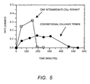
- Figure 5 illustrates the fixed delivery of current as a function of time from a battery prepared in accordance to this invention.
- a limiting supply of zinc serves as the oxidizable species
- the reducible species was silver chloride
- one intermediate cell was used.
- a current-time profile of a conventional galvanic system is charted as well, also using zinc as an oxidizable species in limiting supply and silver chloride as the reducible species.
- the current level (and consequently the medication delivery rate) is higher in this invention, owing to a higher application voltage (2 volts vs. 1 volt).
- FIG. 6 is an illustration of the invention similar to Figure 1 with an integrated switch, again using zinc and silver chloride as the oxidizable and reducible species.
- Activation of the switch in "A" position allows a high application voltage (in this case to 2 volts) and higher medication flow.
- Adjustment of the switch to the "B" position reduces voltage (in this case to 1 volt) and to a lower medication flow.
- this shows how this invention can be modified to allow manual adjustment of medication flow between high and low flow rates with a simple switch assembly.
- the current flow may be shut off in the illustrated neutral position.
Landscapes
- Health & Medical Sciences (AREA)
- Engineering & Computer Science (AREA)
- Bioinformatics & Cheminformatics (AREA)
- Pharmacology & Pharmacy (AREA)
- Biomedical Technology (AREA)
- Nuclear Medicine, Radiotherapy & Molecular Imaging (AREA)
- Radiology & Medical Imaging (AREA)
- Life Sciences & Earth Sciences (AREA)
- Animal Behavior & Ethology (AREA)
- General Health & Medical Sciences (AREA)
- Public Health (AREA)
- Veterinary Medicine (AREA)
- Electrotherapy Devices (AREA)
- Medicinal Preparation (AREA)
- Medicines Containing Plant Substances (AREA)
- Acyclic And Carbocyclic Compounds In Medicinal Compositions (AREA)
- Nitrogen Condensed Heterocyclic Rings (AREA)
- Pharmaceuticals Containing Other Organic And Inorganic Compounds (AREA)
Applications Claiming Priority (5)
| Application Number | Priority Date | Filing Date | Title |
|---|---|---|---|
| US17371099P | 1999-12-30 | 1999-12-30 | |
| US173710P | 1999-12-30 | ||
| US613984 | 2000-07-11 | ||
| US09/613,984 US6421561B1 (en) | 1999-12-30 | 2000-07-11 | Rate adjustable drug delivery system |
| PCT/US2000/027301 WO2001049365A1 (en) | 1999-12-30 | 2000-10-04 | Rate adjustable drug delivery system |
Publications (2)
| Publication Number | Publication Date |
|---|---|
| EP1242142A1 EP1242142A1 (en) | 2002-09-25 |
| EP1242142B1 true EP1242142B1 (en) | 2007-09-05 |
Family
ID=26869460
Family Applications (1)
| Application Number | Title | Priority Date | Filing Date |
|---|---|---|---|
| EP00973406A Expired - Lifetime EP1242142B1 (en) | 1999-12-30 | 2000-10-04 | Rate adjustable drug delivery system |
Country Status (7)
| Country | Link |
|---|---|
| US (2) | US6421561B1 (ja) |
| EP (1) | EP1242142B1 (ja) |
| JP (2) | JP4294247B2 (ja) |
| AT (1) | ATE372146T1 (ja) |
| AU (1) | AU1191301A (ja) |
| DE (1) | DE60036306T2 (ja) |
| WO (1) | WO2001049365A1 (ja) |
Families Citing this family (92)
| Publication number | Priority date | Publication date | Assignee | Title |
|---|---|---|---|---|
| EP1115454B1 (en) | 1998-08-31 | 2006-10-25 | Travanti Pharma Inc | Controlled dosage drug delivery system |
| US6421561B1 (en) | 1999-12-30 | 2002-07-16 | Birch Point Medical, Inc. | Rate adjustable drug delivery system |
| US6653014B2 (en) * | 2001-05-30 | 2003-11-25 | Birch Point Medical, Inc. | Power sources for iontophoretic drug delivery systems |
| US6746790B2 (en) * | 2001-08-15 | 2004-06-08 | Metallic Power, Inc. | Power system including heat removal unit for providing backup power to one or more loads |
| AU2002347567B2 (en) * | 2001-10-24 | 2008-07-17 | Power Paper Ltd. | Dermal patch |
| US7349733B2 (en) * | 2001-11-02 | 2008-03-25 | Ceramatel, Inc. | Iontophoretic drug delivery systems |
| US7047069B2 (en) * | 2002-02-04 | 2006-05-16 | Ceramatec, Inc. | Iontophoretic fluid delivery device |
| US6775570B2 (en) * | 2002-02-04 | 2004-08-10 | Ceramatec, Inc. | Iontophoretic treatment device |
| US20040009398A1 (en) | 2002-06-19 | 2004-01-15 | Dorfman Jay Robert | Zinc polymer thick film composition |
| US20060009730A2 (en) * | 2002-07-29 | 2006-01-12 | Eemso, Inc. | Iontophoretic Transdermal Delivery of One or More Therapeutic Agents |
| ATE359802T1 (de) * | 2002-10-04 | 2007-05-15 | Photokinetix Inc | Photokinetische abgabe von biologisch aktiven subtanzen unter verwendung von pulsierendem inkohaerentem licht. |
| US6745071B1 (en) | 2003-02-21 | 2004-06-01 | Birch Point Medical, Inc. | Iontophoretic drug delivery system |
| US8734421B2 (en) * | 2003-06-30 | 2014-05-27 | Johnson & Johnson Consumer Companies, Inc. | Methods of treating pores on the skin with electricity |
| US7486989B2 (en) * | 2003-06-30 | 2009-02-03 | Johnson & Johnson Consumer Companies, Inc. | Device for delivery of oxidizing agents to barrier membranes |
| US7477940B2 (en) * | 2003-06-30 | 2009-01-13 | J&J Consumer Companies, Inc. | Methods of administering an active agent to a human barrier membrane with galvanic generated electricity |
| US7480530B2 (en) | 2003-06-30 | 2009-01-20 | Johnson & Johnson Consumer Companies, Inc. | Device for treatment of barrier membranes |
| US20040265395A1 (en) * | 2003-06-30 | 2004-12-30 | Ying Sun | Device for delivery of reducing agents to barrier membranes |
| US7479133B2 (en) * | 2003-06-30 | 2009-01-20 | Johnson & Johnson Consumer Companies, Inc. | Methods of treating acne and rosacea with galvanic generated electricity |
| US7477939B2 (en) * | 2003-06-30 | 2009-01-13 | Johnson & Johnson Consumer Companies, Inc. | Methods of treating a wound with galvanic generated electricity |
| US7477938B2 (en) * | 2003-06-30 | 2009-01-13 | Johnson & Johnson Cosumer Companies, Inc. | Device for delivery of active agents to barrier membranes |
| US7476222B2 (en) * | 2003-06-30 | 2009-01-13 | Johnson & Johnson Consumer Companies, Inc. | Methods of reducing the appearance of pigmentation with galvanic generated electricity |
| US7477941B2 (en) * | 2003-06-30 | 2009-01-13 | Johnson & Johnson Consumer Companies, Inc. | Methods of exfoliating the skin with electricity |
| US7507228B2 (en) * | 2003-06-30 | 2009-03-24 | Johnson & Johnson Consumer Companies, Inc. | Device containing a light emitting diode for treatment of barrier membranes |
| CA2532786A1 (en) | 2003-07-14 | 2005-01-20 | Power Paper Ltd. | Method, apparatus, and kit for onychomycosis treatment using electrokinetic transport of substances |
| US20050038473A1 (en) * | 2003-07-14 | 2005-02-17 | Dov Tamarkin | Device and method for the treatment of pilosebaceous disorders |
| US20050234516A1 (en) * | 2004-02-16 | 2005-10-20 | Gueret Jean-Louis H | Treatment kit, composite structure, electric exciter, and cosmetic treatment method |
| US8722235B2 (en) | 2004-04-21 | 2014-05-13 | Blue Spark Technologies, Inc. | Thin printable flexible electrochemical cell and method of making the same |
| US8029927B2 (en) | 2005-03-22 | 2011-10-04 | Blue Spark Technologies, Inc. | Thin printable electrochemical cell utilizing a “picture frame” and methods of making the same |
| US7856263B2 (en) * | 2005-04-22 | 2010-12-21 | Travanti Pharma Inc. | Transdermal systems for the delivery of therapeutic agents including granisetron using iontophoresis |
| US8722233B2 (en) | 2005-05-06 | 2014-05-13 | Blue Spark Technologies, Inc. | RFID antenna-battery assembly and the method to make the same |
| JP2007037868A (ja) * | 2005-08-05 | 2007-02-15 | Transcutaneous Technologies Inc | 経皮投与装置及びその制御方法 |
| US8386030B2 (en) | 2005-08-08 | 2013-02-26 | Tti Ellebeau, Inc. | Iontophoresis device |
| US8295922B2 (en) * | 2005-08-08 | 2012-10-23 | Tti Ellebeau, Inc. | Iontophoresis device |
| US20070060860A1 (en) * | 2005-08-18 | 2007-03-15 | Transcutaneous Technologies Inc. | Iontophoresis device |
| JPWO2007026671A1 (ja) * | 2005-08-29 | 2009-03-05 | Tti・エルビュー株式会社 | センサからの情報により投与すべき薬剤の選定を行うイオントフォレーシス装置 |
| BRPI0616165A2 (pt) | 2005-09-15 | 2011-06-07 | Tti Ellebeau Inc | dispositivo de iontoforese do tipo de haste |
| US20070071807A1 (en) * | 2005-09-28 | 2007-03-29 | Hidero Akiyama | Capsule-type drug-releasing device and capsule-type drug-releasing device system |
| US20070078445A1 (en) * | 2005-09-30 | 2007-04-05 | Curt Malloy | Synchronization apparatus and method for iontophoresis device to deliver active agents to biological interfaces |
| US20070232983A1 (en) * | 2005-09-30 | 2007-10-04 | Smith Gregory A | Handheld apparatus to deliver active agents to biological interfaces |
| JP4804904B2 (ja) * | 2005-12-09 | 2011-11-02 | Tti・エルビュー株式会社 | イオントフォレーシス装置包装品 |
| WO2007086057A1 (en) | 2006-01-26 | 2007-08-02 | Power Paper Ltd | Power source electrode treatment device |
| CN104138634B (zh) * | 2006-04-13 | 2016-09-07 | 梯瓦制药国际有限责任公司 | 递送抗偏头痛化合物的透皮方法和系统 |
| US7904146B2 (en) * | 2006-11-13 | 2011-03-08 | Travanti Pharma Inc. | Transdermal systems for the delivery of ionic agents directly to open wounds and surgically repaired incisions |
| US8332028B2 (en) * | 2006-11-28 | 2012-12-11 | Polyplus Battery Company | Protected lithium electrodes for electro-transport drug delivery |
| WO2008070524A2 (en) * | 2006-12-01 | 2008-06-12 | Tti Ellebeau, Inc. | Systems, devices, and methods for powering and/or controlling devices, for instance transdermal delivery devices |
| US20080177219A1 (en) * | 2007-01-23 | 2008-07-24 | Joshi Ashok V | Method for Iontophoretic Fluid Delivery |
| US7687678B2 (en) * | 2007-05-10 | 2010-03-30 | Cisco Technology, Inc. | Electronic bandage with flexible electronic controller |
| US8197844B2 (en) | 2007-06-08 | 2012-06-12 | Activatek, Inc. | Active electrode for transdermal medicament administration |
| WO2009006349A2 (en) * | 2007-06-29 | 2009-01-08 | Polyplus Battery Company | Electrotransport devices, methods and drug electrode assemblies |
| EP2176814A4 (en) | 2007-07-18 | 2012-06-13 | Blue Spark Technologies Inc | INTEGRATED ELECTRONIC DEVICE AND METHODS OF PREPARATION |
| US20090069740A1 (en) * | 2007-09-07 | 2009-03-12 | Polyplus Battery Company | Protected donor electrodes for electro-transport drug delivery |
| WO2009045720A2 (en) | 2007-09-28 | 2009-04-09 | Johnson & Johnson Consumer Companies, Inc. | Electricity-generating particulates and the use thereof |
| US8195287B2 (en) * | 2007-12-05 | 2012-06-05 | The Invention Science Fund I, Llc | Method for electrical modulation of neural conduction |
| US8165668B2 (en) * | 2007-12-05 | 2012-04-24 | The Invention Science Fund I, Llc | Method for magnetic modulation of neural conduction |
| US8165669B2 (en) * | 2007-12-05 | 2012-04-24 | The Invention Science Fund I, Llc | System for magnetic modulation of neural conduction |
| US8170658B2 (en) | 2007-12-05 | 2012-05-01 | The Invention Science Fund I, Llc | System for electrical modulation of neural conduction |
| US8160695B2 (en) * | 2007-12-05 | 2012-04-17 | The Invention Science Fund I, Llc | System for chemical modulation of neural activity |
| US8180446B2 (en) * | 2007-12-05 | 2012-05-15 | The Invention Science Fund I, Llc | Method and system for cyclical neural modulation based on activity state |
| US8170659B2 (en) | 2007-12-05 | 2012-05-01 | The Invention Science Fund I, Llc | Method for thermal modulation of neural activity |
| US8233976B2 (en) | 2007-12-05 | 2012-07-31 | The Invention Science Fund I, Llc | System for transdermal chemical modulation of neural activity |
| US20090149797A1 (en) * | 2007-12-05 | 2009-06-11 | Searete Llc, A Limited Liability Corporation Of The State Of Delaware | System for reversible chemical modulation of neural activity |
| US8574754B2 (en) | 2007-12-19 | 2013-11-05 | Blue Spark Technologies, Inc. | High current thin electrochemical cell and methods of making the same |
| US20110160640A1 (en) * | 2008-01-18 | 2011-06-30 | Yanaki Jamal S | Operation management of active transdermal medicament patch |
| US8862223B2 (en) * | 2008-01-18 | 2014-10-14 | Activatek, Inc. | Active transdermal medicament patch and circuit board for same |
| KR101593590B1 (ko) | 2008-02-22 | 2016-02-12 | 일리노이즈 툴 워크스 인코포레이티드 | 패스너 조립체 |
| KR100950584B1 (ko) * | 2008-04-07 | 2010-04-01 | 주식회사로케트전기 | 전지 일체형 이온토포레시스 패치 |
| US8155737B2 (en) | 2008-06-19 | 2012-04-10 | Nupathe, Inc. | Pharmacokinetics of iontophoretic sumatriptan administration |
| US8366600B2 (en) * | 2008-06-19 | 2013-02-05 | Nupathe Inc. | Polyamine enhanced formulations for triptan compound iontophoresis |
| US8150525B2 (en) * | 2008-08-27 | 2012-04-03 | Johnson & Johnson Consumer Companies, Inc. | Treatment of hyperhydrosis |
| US20100268335A1 (en) | 2009-03-27 | 2010-10-21 | Chunlin Yang | Medical devices with galvanic particulates |
| EP2411060A2 (en) * | 2009-03-27 | 2012-02-01 | Advanced Technologies and Regenerative Medicine, LLC | Medical devices with galvanic particulates |
| US20120089232A1 (en) | 2009-03-27 | 2012-04-12 | Jennifer Hagyoung Kang Choi | Medical devices with galvanic particulates |
| US20110060419A1 (en) | 2009-03-27 | 2011-03-10 | Jennifer Hagyoung Kang Choi | Medical devices with galvanic particulates |
| JP2012529353A (ja) * | 2009-06-09 | 2012-11-22 | Tti・エルビュー株式会社 | 長寿命高容量電極、装置および製造方法 |
| JP6116246B2 (ja) | 2009-08-10 | 2017-04-19 | テバ・ファーマシューティカルズ・インターナショナル・ゲー・エム・ベー・ハー | イオントフォレシスにより悪心および片頭痛を治療するための方法 |
| WO2011046927A1 (en) * | 2009-10-13 | 2011-04-21 | Nupathe,Inc. | Transdermal methods and systems for the delivery of rizatriptan |
| KR101051977B1 (ko) * | 2009-10-22 | 2011-07-26 | 주식회사로케트전기 | 박형전지를 구비하는 장치 및 이온토포레시스 패치 |
| KR20120091335A (ko) * | 2009-11-13 | 2012-08-17 | 존슨 앤드 존슨 컨수머 캄파니즈, 인코포레이티드 | 갈바닉 피부 치료 장치 |
| US20120259269A1 (en) | 2011-04-08 | 2012-10-11 | Tyco Healthcare Group Lp | Iontophoresis drug delivery system and method for denervation of the renal sympathetic nerve and iontophoretic drug delivery |
| WO2013044224A2 (en) | 2011-09-22 | 2013-03-28 | Blue Spark Technologies, Inc. | Cell attachment method |
| US10046160B1 (en) | 2011-09-30 | 2018-08-14 | Nse Products, Inc. | Electronic skin treatment device and method |
| WO2013177202A1 (en) | 2012-05-21 | 2013-11-28 | Blue Spark Technologies, Inc. | Multi-cell battery |
| CN104936513B (zh) | 2012-11-01 | 2018-01-12 | 蓝色火花科技有限公司 | 体温记录贴片 |
| US9444078B2 (en) | 2012-11-27 | 2016-09-13 | Blue Spark Technologies, Inc. | Battery cell construction |
| EP3226964B1 (en) * | 2014-12-05 | 2018-10-24 | NMR Technology AS | An electrochemical device for releasing ions |
| US9693689B2 (en) | 2014-12-31 | 2017-07-04 | Blue Spark Technologies, Inc. | Body temperature logging patch |
| US10849501B2 (en) | 2017-08-09 | 2020-12-01 | Blue Spark Technologies, Inc. | Body temperature logging patch |
| CA3103274A1 (en) | 2018-06-14 | 2019-12-19 | Anton SABIEV | Wireless iontophoresis patch and controller |
| WO2021202999A1 (en) | 2020-04-03 | 2021-10-07 | Nse Products, Inc. | Modulated waveform treatment device and method |
| USD933840S1 (en) | 2020-04-21 | 2021-10-19 | Nse Products, Inc. | Microcurrent skin treatment device |
| FR3138988A1 (fr) * | 2022-08-26 | 2024-03-01 | Feeligreen | Dispositif de traitement de la peau |
| FR3138989A1 (fr) * | 2022-08-26 | 2024-03-01 | Feeligreen | Dispositif de traitement de la peau |
Family Cites Families (53)
| Publication number | Priority date | Publication date | Assignee | Title |
|---|---|---|---|---|
| US770014A (en) | 1904-09-13 | Electfiomedical | ||
| US116562A (en) | 1871-07-04 | Improvement in medicated voltaic plasters | ||
| US175974A (en) | 1876-04-11 | Improvement in electro-medical plasters | ||
| US385556A (en) | 1888-07-03 | Medicated electric belt | ||
| US393741A (en) | 1888-12-04 | Voltaic plaster | ||
| US222276A (en) | 1879-12-02 | Improvement in combined galvanic and medicated pad | ||
| US857664A (en) | 1907-01-10 | 1907-06-25 | David R Overman | Electromedical appliance. |
| BE399044A (ja) | 1933-09-09 | |||
| CH185726A (fr) | 1935-06-26 | 1936-08-15 | Genevoise Instr Physique | Dispositif appliqué à une machine-outil et destiné à faciliter le travail de l'ouvrier desservant celle-ci. |
| FR2263792A1 (en) | 1974-03-12 | 1975-10-10 | Bondivenne Jean | Ionotherapy current generator - comprises thin flexible bag giving percutaneous medicament penetration |
| US4035554A (en) | 1974-08-05 | 1977-07-12 | Lockheed Missiles & Space Company, Inc. | Self pumping electrochemical cell |
| US4767401A (en) | 1975-04-22 | 1988-08-30 | Maurice Seiderman | Iontophoretic administration of ionizable or polar medicaments to a mammalian body |
| DE3273269D1 (en) | 1981-03-06 | 1986-10-23 | Medtronic Inc | Iontophoretic electrode |
| WO1984004045A1 (en) | 1983-04-15 | 1984-10-25 | Jack Kenneth Ibbott | Therapeutic method and appliance employing flat battery |
| US4856188A (en) | 1984-10-12 | 1989-08-15 | Drug Delivery Systems Inc. | Method for making disposable and/or replenishable transdermal drug applicators |
| US4622031A (en) | 1983-08-18 | 1986-11-11 | Drug Delivery Systems Inc. | Indicator for electrophoretic transcutaneous drug delivery device |
| US5651768A (en) | 1983-08-18 | 1997-07-29 | Drug Delivery Systems, Inc. | Transdermal drug applicator and electrodes therefor |
| US5605536A (en) | 1983-08-18 | 1997-02-25 | Drug Delivery Systems Inc. | Transdermal drug applicator and electrodes therefor |
| EP0308572B1 (en) | 1983-09-01 | 1995-11-08 | Hisamitsu Pharmaceutical Co., Inc. | An iontophoresis device |
| US5135477A (en) | 1984-10-29 | 1992-08-04 | Medtronic, Inc. | Iontophoretic drug delivery |
| US4747819A (en) | 1984-10-29 | 1988-05-31 | Medtronic, Inc. | Iontophoretic drug delivery |
| USH178H (en) | 1985-11-05 | 1986-12-02 | The United States Of America As Represented By The Secretary Of The Army | Reserve battery with improved wet-stand characteristics |
| US4626482A (en) | 1985-11-18 | 1986-12-02 | Alupower, Inc. | Metal/air batteries |
| US4722726A (en) | 1986-02-12 | 1988-02-02 | Key Pharmaceuticals, Inc. | Method and apparatus for iontophoretic drug delivery |
| US4752285B1 (en) | 1986-03-19 | 1995-08-22 | Univ Utah Res Found | Methods and apparatus for iontophoresis application of medicaments |
| FR2616333A1 (fr) | 1987-06-12 | 1988-12-16 | Cird | Procede d'ionophorese pour administrer une substance dissoute ou partiellement dissoute, par voie percutanee ou perungueale et dispositif correspondant |
| US5162042A (en) | 1988-07-05 | 1992-11-10 | Alza Corporation | Electrotransport transdermal system |
| US4927408A (en) | 1988-10-03 | 1990-05-22 | Alza Corporation | Electrotransport transdermal system |
| US4950229A (en) | 1989-09-25 | 1990-08-21 | Becton, Dickinson And Company | Apparatus for an electrode used for iontophoresis |
| DE4014913C2 (de) | 1990-05-10 | 1996-05-15 | Lohmann Therapie Syst Lts | Miniaturisiertes transdermales therapeutisches System für die Iontophorese |
| DE4114677A1 (de) | 1990-10-10 | 1992-02-27 | Mario Bergner | Applikationsanordnung verschiedener elektrisch verbundener metalle am menschlichen koerper zu einem bioelektrischen system im sinne der elektrochemischen spannungsreihe mit spannungserhoehung bei moeglicher verwendung handelsueblicher ekg-elektrodenpflaster |
| US5431625A (en) | 1991-02-01 | 1995-07-11 | Empi, Inc. | Iontophoresis electronic device having a ramped output current |
| US5254081A (en) | 1991-02-01 | 1993-10-19 | Empi, Inc. | Multiple site drug iontophoresis electronic device and method |
| US5221254A (en) | 1991-04-02 | 1993-06-22 | Alza Corporation | Method for reducing sensation in iontophoretic drug delivery |
| US5160315A (en) | 1991-04-05 | 1992-11-03 | Minnesota Mining And Manufacturing Company | Combined adhesive strip and transparent dressing delivery system |
| US5405317A (en) | 1991-05-03 | 1995-04-11 | Alza Corporation | Iontophoretic delivery device |
| US5203768A (en) | 1991-07-24 | 1993-04-20 | Alza Corporation | Transdermal delivery device |
| US5201924A (en) | 1991-09-03 | 1993-04-13 | General Motors Corporation | Filling mat-immobilized-electrolyte batteries |
| US5356632A (en) | 1991-09-12 | 1994-10-18 | S.I. Scientific Innovations Ltd. | Transdermal drug delivery device |
| JPH05198303A (ja) * | 1992-01-21 | 1993-08-06 | Dai Ichi Kogyo Seiyaku Co Ltd | 電 池 |
| FR2687321B1 (fr) | 1992-02-14 | 1999-04-16 | Elf Aquitaine | Dispositif d'ionophorese pour l'administration transcutanee d'une quantite totale donnee d'un principe actif a un sujet. |
| US5295979A (en) | 1992-03-27 | 1994-03-22 | P & D Medical Coatings, Inc. | Urinary catheter and system |
| DE69407061T2 (de) | 1992-06-02 | 1998-06-04 | Alza Corp | Abgabevorrichtung zur elektrischen übertragung von arzneimitteln |
| US5333971A (en) * | 1992-11-03 | 1994-08-02 | Lewis John A | Interlocking bulkhead |
| US5322520A (en) | 1992-11-12 | 1994-06-21 | Implemed, Inc. | Iontophoretic structure for medical devices |
| US5298017A (en) | 1992-12-29 | 1994-03-29 | Alza Corporation | Layered electrotransport drug delivery system |
| US5458569A (en) | 1993-06-08 | 1995-10-17 | Becton Dickinson And Company | Wearable iontophoresis system |
| US5533971A (en) | 1993-09-03 | 1996-07-09 | Alza Corporation | Reduction of skin irritation during electrotransport |
| US5983130A (en) | 1995-06-07 | 1999-11-09 | Alza Corporation | Electrotransport agent delivery method and apparatus |
| US5759564A (en) | 1996-04-16 | 1998-06-02 | Implemed, Inc. | Iontophoretic material |
| US5772688A (en) | 1996-06-20 | 1998-06-30 | Polytronics, Ltd. | Skin-contact type medical treatment apparatus |
| US6009344A (en) | 1997-07-25 | 1999-12-28 | Becton, Dickinson And Company | Iontophoretic drug delivery system |
| US6421561B1 (en) | 1999-12-30 | 2002-07-16 | Birch Point Medical, Inc. | Rate adjustable drug delivery system |
-
2000
- 2000-07-11 US US09/613,984 patent/US6421561B1/en not_active Expired - Lifetime
- 2000-10-04 AT AT00973406T patent/ATE372146T1/de not_active IP Right Cessation
- 2000-10-04 JP JP2001549729A patent/JP4294247B2/ja not_active Expired - Fee Related
- 2000-10-04 EP EP00973406A patent/EP1242142B1/en not_active Expired - Lifetime
- 2000-10-04 AU AU11913/01A patent/AU1191301A/en not_active Abandoned
- 2000-10-04 DE DE60036306T patent/DE60036306T2/de not_active Expired - Lifetime
- 2000-10-04 WO PCT/US2000/027301 patent/WO2001049365A1/en active IP Right Grant
-
2002
- 2002-06-03 US US10/162,473 patent/US7016723B2/en not_active Expired - Lifetime
-
2006
- 2006-08-25 JP JP2006228645A patent/JP2007014793A/ja not_active Abandoned
Non-Patent Citations (1)
| Title |
|---|
| None * |
Also Published As
| Publication number | Publication date |
|---|---|
| EP1242142A1 (en) | 2002-09-25 |
| AU1191301A (en) | 2001-07-16 |
| ATE372146T1 (de) | 2007-09-15 |
| DE60036306T2 (de) | 2008-06-05 |
| WO2001049365A1 (en) | 2001-07-12 |
| DE60036306D1 (de) | 2007-10-18 |
| JP4294247B2 (ja) | 2009-07-08 |
| JP2007014793A (ja) | 2007-01-25 |
| US7016723B2 (en) | 2006-03-21 |
| US6421561B1 (en) | 2002-07-16 |
| JP2003530909A (ja) | 2003-10-21 |
| US20020188241A1 (en) | 2002-12-12 |
Similar Documents
| Publication | Publication Date | Title |
|---|---|---|
| EP1242142B1 (en) | Rate adjustable drug delivery system | |
| EP1115454B1 (en) | Controlled dosage drug delivery system | |
| JP4384128B2 (ja) | 電気治療における薬物送達の方法及び装置 | |
| US7047069B2 (en) | Iontophoretic fluid delivery device | |
| US6775570B2 (en) | Iontophoretic treatment device | |
| US5162042A (en) | Electrotransport transdermal system | |
| US5057072A (en) | Iontophoresis electrode | |
| US5445606A (en) | Indicator for iontophoresis system | |
| US6009344A (en) | Iontophoretic drug delivery system | |
| AU2003275411B2 (en) | Dosage control electrode for iontophoresis device | |
| KR20050103941A (ko) | 이온삼투압 약물전달시스템 | |
| EP1718363B1 (en) | Iontophoretic electrode | |
| EP0429552B1 (en) | Iontophoresis electrode | |
| Phipps et al. | IONTOPHORETIC DRUG DELIVERY: ADVANTAGES AND LIMITATIONS | |
| MXPA98005943A (en) | An iontoforet drug supply system |
Legal Events
| Date | Code | Title | Description |
|---|---|---|---|
| PUAI | Public reference made under article 153(3) epc to a published international application that has entered the european phase |
Free format text: ORIGINAL CODE: 0009012 |
|
| 17P | Request for examination filed |
Effective date: 20020712 |
|
| AK | Designated contracting states |
Kind code of ref document: A1 Designated state(s): AT BE CH CY DE DK ES FI FR GB GR IE IT LI LU MC NL PT SE |
|
| 17Q | First examination report despatched |
Effective date: 20050304 |
|
| RAP1 | Party data changed (applicant data changed or rights of an application transferred) |
Owner name: TRAVANTI PHARMA INC |
|
| 17Q | First examination report despatched |
Effective date: 20050304 |
|
| GRAP | Despatch of communication of intention to grant a patent |
Free format text: ORIGINAL CODE: EPIDOSNIGR1 |
|
| GRAS | Grant fee paid |
Free format text: ORIGINAL CODE: EPIDOSNIGR3 |
|
| GRAA | (expected) grant |
Free format text: ORIGINAL CODE: 0009210 |
|
| AK | Designated contracting states |
Kind code of ref document: B1 Designated state(s): AT BE CH CY DE DK ES FI FR GB GR IE IT LI LU MC NL PT SE |
|
| REG | Reference to a national code |
Ref country code: GB Ref legal event code: FG4D |
|
| REG | Reference to a national code |
Ref country code: CH Ref legal event code: EP |
|
| REF | Corresponds to: |
Ref document number: 60036306 Country of ref document: DE Date of ref document: 20071018 Kind code of ref document: P |
|
| REG | Reference to a national code |
Ref country code: IE Ref legal event code: FG4D |
|
| PG25 | Lapsed in a contracting state [announced via postgrant information from national office to epo] |
Ref country code: ES Free format text: LAPSE BECAUSE OF FAILURE TO SUBMIT A TRANSLATION OF THE DESCRIPTION OR TO PAY THE FEE WITHIN THE PRESCRIBED TIME-LIMIT Effective date: 20071216 Ref country code: FI Free format text: LAPSE BECAUSE OF FAILURE TO SUBMIT A TRANSLATION OF THE DESCRIPTION OR TO PAY THE FEE WITHIN THE PRESCRIBED TIME-LIMIT Effective date: 20070905 |
|
| PG25 | Lapsed in a contracting state [announced via postgrant information from national office to epo] |
Ref country code: CH Free format text: LAPSE BECAUSE OF FAILURE TO SUBMIT A TRANSLATION OF THE DESCRIPTION OR TO PAY THE FEE WITHIN THE PRESCRIBED TIME-LIMIT Effective date: 20070905 Ref country code: LI Free format text: LAPSE BECAUSE OF FAILURE TO SUBMIT A TRANSLATION OF THE DESCRIPTION OR TO PAY THE FEE WITHIN THE PRESCRIBED TIME-LIMIT Effective date: 20070905 Ref country code: AT Free format text: LAPSE BECAUSE OF FAILURE TO SUBMIT A TRANSLATION OF THE DESCRIPTION OR TO PAY THE FEE WITHIN THE PRESCRIBED TIME-LIMIT Effective date: 20070905 |
|
| NLV1 | Nl: lapsed or annulled due to failure to fulfill the requirements of art. 29p and 29m of the patents act | ||
| PG25 | Lapsed in a contracting state [announced via postgrant information from national office to epo] |
Ref country code: BE Free format text: LAPSE BECAUSE OF FAILURE TO SUBMIT A TRANSLATION OF THE DESCRIPTION OR TO PAY THE FEE WITHIN THE PRESCRIBED TIME-LIMIT Effective date: 20070905 |
|
| REG | Reference to a national code |
Ref country code: CH Ref legal event code: PL |
|
| PG25 | Lapsed in a contracting state [announced via postgrant information from national office to epo] |
Ref country code: GR Free format text: LAPSE BECAUSE OF FAILURE TO SUBMIT A TRANSLATION OF THE DESCRIPTION OR TO PAY THE FEE WITHIN THE PRESCRIBED TIME-LIMIT Effective date: 20071206 Ref country code: NL Free format text: LAPSE BECAUSE OF FAILURE TO SUBMIT A TRANSLATION OF THE DESCRIPTION OR TO PAY THE FEE WITHIN THE PRESCRIBED TIME-LIMIT Effective date: 20070905 |
|
| EN | Fr: translation not filed | ||
| PG25 | Lapsed in a contracting state [announced via postgrant information from national office to epo] |
Ref country code: MC Free format text: LAPSE BECAUSE OF NON-PAYMENT OF DUE FEES Effective date: 20071031 Ref country code: PT Free format text: LAPSE BECAUSE OF FAILURE TO SUBMIT A TRANSLATION OF THE DESCRIPTION OR TO PAY THE FEE WITHIN THE PRESCRIBED TIME-LIMIT Effective date: 20080206 |
|
| PG25 | Lapsed in a contracting state [announced via postgrant information from national office to epo] |
Ref country code: SE Free format text: LAPSE BECAUSE OF FAILURE TO SUBMIT A TRANSLATION OF THE DESCRIPTION OR TO PAY THE FEE WITHIN THE PRESCRIBED TIME-LIMIT Effective date: 20071205 |
|
| PLBE | No opposition filed within time limit |
Free format text: ORIGINAL CODE: 0009261 |
|
| STAA | Information on the status of an ep patent application or granted ep patent |
Free format text: STATUS: NO OPPOSITION FILED WITHIN TIME LIMIT |
|
| PG25 | Lapsed in a contracting state [announced via postgrant information from national office to epo] |
Ref country code: DK Free format text: LAPSE BECAUSE OF FAILURE TO SUBMIT A TRANSLATION OF THE DESCRIPTION OR TO PAY THE FEE WITHIN THE PRESCRIBED TIME-LIMIT Effective date: 20070905 |
|
| ET | Fr: translation filed | ||
| REG | Reference to a national code |
Ref country code: FR Ref legal event code: EERR Free format text: CORRECTION DE BOPI 08/18 - BREVETS EUROPEENS DONT LA TRADUCTION N A PAS ETE REMISE A L INPI. IL Y A LIEU DE SUPPRIMER : LA MENTION DE LA NON-REMISE. LA REMISE DE LA TRADUCTION EST PUBLIEE DANS LE PRESENT BOPI. |
|
| 26N | No opposition filed |
Effective date: 20080606 |
|
| PG25 | Lapsed in a contracting state [announced via postgrant information from national office to epo] |
Ref country code: FR Free format text: LAPSE BECAUSE OF FAILURE TO SUBMIT A TRANSLATION OF THE DESCRIPTION OR TO PAY THE FEE WITHIN THE PRESCRIBED TIME-LIMIT Effective date: 20080502 |
|
| PG25 | Lapsed in a contracting state [announced via postgrant information from national office to epo] |
Ref country code: IE Free format text: LAPSE BECAUSE OF NON-PAYMENT OF DUE FEES Effective date: 20071004 |
|
| PG25 | Lapsed in a contracting state [announced via postgrant information from national office to epo] |
Ref country code: CY Free format text: LAPSE BECAUSE OF FAILURE TO SUBMIT A TRANSLATION OF THE DESCRIPTION OR TO PAY THE FEE WITHIN THE PRESCRIBED TIME-LIMIT Effective date: 20070905 |
|
| PG25 | Lapsed in a contracting state [announced via postgrant information from national office to epo] |
Ref country code: LU Free format text: LAPSE BECAUSE OF NON-PAYMENT OF DUE FEES Effective date: 20071004 |
|
| REG | Reference to a national code |
Ref country code: FR Ref legal event code: TP Owner name: TEIKOKU PHARMA USA, INC., US Effective date: 20120403 |
|
| REG | Reference to a national code |
Ref country code: GB Ref legal event code: 732E Free format text: REGISTERED BETWEEN 20120419 AND 20120425 |
|
| REG | Reference to a national code |
Ref country code: DE Ref legal event code: R082 Ref document number: 60036306 Country of ref document: DE Representative=s name: ANDRAE FLACH HAUG, DE |
|
| REG | Reference to a national code |
Ref country code: DE Ref legal event code: R081 Ref document number: 60036306 Country of ref document: DE Owner name: TEIKOKU PHARMA USA, INC., SAN JOSE, US Free format text: FORMER OWNER: TRAVANTI PHARMA INC., MENDOTA HEIGHTS, MN, US Effective date: 20120625 Ref country code: DE Ref legal event code: R082 Ref document number: 60036306 Country of ref document: DE Representative=s name: ANDRAE WESTENDORP PATENTANWAELTE PARTNERSCHAFT, DE Effective date: 20120625 Ref country code: DE Ref legal event code: R082 Ref document number: 60036306 Country of ref document: DE Representative=s name: FLACH BAUER STAHL PATENTANWAELTE PARTNERSCHAFT, DE Effective date: 20120625 |
|
| REG | Reference to a national code |
Ref country code: FR Ref legal event code: PLFP Year of fee payment: 17 |
|
| REG | Reference to a national code |
Ref country code: FR Ref legal event code: PLFP Year of fee payment: 18 |
|
| PGFP | Annual fee paid to national office [announced via postgrant information from national office to epo] |
Ref country code: FR Payment date: 20170918 Year of fee payment: 18 |
|
| PGFP | Annual fee paid to national office [announced via postgrant information from national office to epo] |
Ref country code: DE Payment date: 20170927 Year of fee payment: 18 |
|
| PGFP | Annual fee paid to national office [announced via postgrant information from national office to epo] |
Ref country code: IT Payment date: 20171024 Year of fee payment: 18 Ref country code: GB Payment date: 20171004 Year of fee payment: 18 |
|
| REG | Reference to a national code |
Ref country code: DE Ref legal event code: R082 Ref document number: 60036306 Country of ref document: DE Representative=s name: FLACH BAUER STAHL PATENTANWAELTE PARTNERSCHAFT, DE |
|
| REG | Reference to a national code |
Ref country code: DE Ref legal event code: R119 Ref document number: 60036306 Country of ref document: DE |
|
| GBPC | Gb: european patent ceased through non-payment of renewal fee |
Effective date: 20181004 |
|
| PG25 | Lapsed in a contracting state [announced via postgrant information from national office to epo] |
Ref country code: DE Free format text: LAPSE BECAUSE OF NON-PAYMENT OF DUE FEES Effective date: 20190501 |
|
| PG25 | Lapsed in a contracting state [announced via postgrant information from national office to epo] |
Ref country code: FR Free format text: LAPSE BECAUSE OF NON-PAYMENT OF DUE FEES Effective date: 20181031 |
|
| PG25 | Lapsed in a contracting state [announced via postgrant information from national office to epo] |
Ref country code: IT Free format text: LAPSE BECAUSE OF NON-PAYMENT OF DUE FEES Effective date: 20181004 Ref country code: GB Free format text: LAPSE BECAUSE OF NON-PAYMENT OF DUE FEES Effective date: 20181004 |