EP1241802A2 - Adaptive Antennenvorrichtung und dazugehöriges Steuerungsverfahren - Google Patents
Adaptive Antennenvorrichtung und dazugehöriges Steuerungsverfahren Download PDFInfo
- Publication number
- EP1241802A2 EP1241802A2 EP02005254A EP02005254A EP1241802A2 EP 1241802 A2 EP1241802 A2 EP 1241802A2 EP 02005254 A EP02005254 A EP 02005254A EP 02005254 A EP02005254 A EP 02005254A EP 1241802 A2 EP1241802 A2 EP 1241802A2
- Authority
- EP
- European Patent Office
- Prior art keywords
- cell
- mobile
- antenna device
- mobile stations
- mobile station
- Prior art date
- Legal status (The legal status is an assumption and is not a legal conclusion. Google has not performed a legal analysis and makes no representation as to the accuracy of the status listed.)
- Granted
Links
- 230000003044 adaptive effect Effects 0.000 title claims abstract description 29
- 238000000034 method Methods 0.000 title claims description 17
- 230000005540 biological transmission Effects 0.000 claims abstract description 65
- 238000004891 communication Methods 0.000 claims description 25
- 238000010586 diagram Methods 0.000 description 10
- 238000010295 mobile communication Methods 0.000 description 7
- 230000001413 cellular effect Effects 0.000 description 4
- 239000012141 concentrate Substances 0.000 description 2
- 239000000470 constituent Substances 0.000 description 2
- 230000015556 catabolic process Effects 0.000 description 1
- 238000006731 degradation reaction Methods 0.000 description 1
- 230000006866 deterioration Effects 0.000 description 1
- 230000035945 sensitivity Effects 0.000 description 1
- 238000004513 sizing Methods 0.000 description 1
Images


Classifications
-
- H—ELECTRICITY
- H04—ELECTRIC COMMUNICATION TECHNIQUE
- H04W—WIRELESS COMMUNICATION NETWORKS
- H04W52/00—Power management, e.g. Transmission Power Control [TPC] or power classes
- H04W52/04—Transmission power control [TPC]
- H04W52/38—TPC being performed in particular situations
- H04W52/42—TPC being performed in particular situations in systems with time, space, frequency or polarisation diversity
-
- H—ELECTRICITY
- H04—ELECTRIC COMMUNICATION TECHNIQUE
- H04B—TRANSMISSION
- H04B7/00—Radio transmission systems, i.e. using radiation field
- H04B7/02—Diversity systems; Multi-antenna system, i.e. transmission or reception using multiple antennas
- H04B7/04—Diversity systems; Multi-antenna system, i.e. transmission or reception using multiple antennas using two or more spaced independent antennas
- H04B7/06—Diversity systems; Multi-antenna system, i.e. transmission or reception using multiple antennas using two or more spaced independent antennas at the transmitting station
- H04B7/0613—Diversity systems; Multi-antenna system, i.e. transmission or reception using multiple antennas using two or more spaced independent antennas at the transmitting station using simultaneous transmission
- H04B7/0615—Diversity systems; Multi-antenna system, i.e. transmission or reception using multiple antennas using two or more spaced independent antennas at the transmitting station using simultaneous transmission of weighted versions of same signal
- H04B7/0617—Diversity systems; Multi-antenna system, i.e. transmission or reception using multiple antennas using two or more spaced independent antennas at the transmitting station using simultaneous transmission of weighted versions of same signal for beam forming
-
- H—ELECTRICITY
- H04—ELECTRIC COMMUNICATION TECHNIQUE
- H04B—TRANSMISSION
- H04B7/00—Radio transmission systems, i.e. using radiation field
- H04B7/02—Diversity systems; Multi-antenna system, i.e. transmission or reception using multiple antennas
- H04B7/04—Diversity systems; Multi-antenna system, i.e. transmission or reception using multiple antennas using two or more spaced independent antennas
- H04B7/08—Diversity systems; Multi-antenna system, i.e. transmission or reception using multiple antennas using two or more spaced independent antennas at the receiving station
- H04B7/0837—Diversity systems; Multi-antenna system, i.e. transmission or reception using multiple antennas using two or more spaced independent antennas at the receiving station using pre-detection combining
- H04B7/0842—Weighted combining
- H04B7/086—Weighted combining using weights depending on external parameters, e.g. direction of arrival [DOA], predetermined weights or beamforming
-
- H—ELECTRICITY
- H04—ELECTRIC COMMUNICATION TECHNIQUE
- H04W—WIRELESS COMMUNICATION NETWORKS
- H04W16/00—Network planning, e.g. coverage or traffic planning tools; Network deployment, e.g. resource partitioning or cells structures
- H04W16/22—Traffic simulation tools or models
-
- H—ELECTRICITY
- H04—ELECTRIC COMMUNICATION TECHNIQUE
- H04W—WIRELESS COMMUNICATION NETWORKS
- H04W52/00—Power management, e.g. Transmission Power Control [TPC] or power classes
- H04W52/04—Transmission power control [TPC]
- H04W52/30—Transmission power control [TPC] using constraints in the total amount of available transmission power
- H04W52/32—TPC of broadcast or control channels
- H04W52/322—Power control of broadcast channels
-
- H—ELECTRICITY
- H04—ELECTRIC COMMUNICATION TECHNIQUE
- H04W—WIRELESS COMMUNICATION NETWORKS
- H04W52/00—Power management, e.g. Transmission Power Control [TPC] or power classes
- H04W52/04—Transmission power control [TPC]
- H04W52/30—Transmission power control [TPC] using constraints in the total amount of available transmission power
- H04W52/34—TPC management, i.e. sharing limited amount of power among users or channels or data types, e.g. cell loading
Definitions
- the present invention relates to an adaptive antenna device wherein desired directive characteristics can be obtained by respectively controlling the amplitude components and phase components of signals transmitted and received by plural antenna elements.
- the present invention relates to an adaptive antenna device preferably used for mobile communications systems in a CDMA (Code Division Multiple Access) scheme.
- Mobile communications systems adopt the cellular scheme.
- a base station radio communicates with a mobile station within a predetermined area (cell) and distributed base stations provide mobile communication services over the vast area.
- the base station which is used in the cellular scheme, transmits an identification signal under constant power to make a mobile station identify its own cell, using a cell identification channel or a pilot channel. Moreover, the base station transmits common information under constant power. using a notice channel, to catalog the location in each mobile station within its own cell.
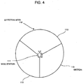
- Fig. 4 is a schematic diagram illustrating the state of an ideal cell (area) under jurisdiction of a base station.
- the effective area 112 where a mobile station can receive the signals of a fixed communication quality or more becomes circular, as shown in Fig. 4.
- a cell is generally divided into sub-areas called sectors to provide mobile communications services.
- Fig. 4 shows the effective area 112 divided into three sectors 113.
- orthogonal codes or dummy noises
- CDMA Code Division Multiple Access
- the communication quality (Eb/NO) between a mobile station and a base station depends on the signal to interference ratio (SIR), a divergence ratio of an orthogonal code, or the number of mobile stations (mobile station density).
- SIR signal to interference ratio
- divergence ratio of an orthogonal code the number of mobile stations (mobile station density).
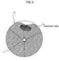
- Fig. 5 is a schematic diagram illustrating the cell in which mobile stations densely exist in an area within the cell.
- the communication channel of a mobile station within the high-density area 114 interferes with the communication channels of other mobile stations. This deteriorates the communication quality of the cell identification channel or the notice information channel and reduces the effective area 112, thus small-sizing the cell in the direction of the high-density area 114 as shown in Fig. 5.
- an area where a mobile station cannot receive the cell identification channel and the notice information channel occurs in the direction of the high-density area 114.
- the communication quality deteriorates in an area of a high-mobile station density within or around cell where the shrinkage phenomenon occurs.
- the transmission power of the cell identification channel or the notice information channel to be transmitted to the cell increases, the communication quality between a base station and a mobile station becomes excessive in an area of a low mobile station density. Consequently, the problem is that the adaptive antenna device is not effective.
- the object of the present invention is to provide an adaptive antenna device capable of compensating the cell shrinkage phenomenon.
- an adaptive antenna device wherein a plurality of antenna elements are provided and wherein amplitude components and phase components of signals transmitted and received via the antenna elements are respectively controlled to obtain desired directive characteristics.
- a baseband receiver for creating a control signal and computing estimated arrival direction information being a result of estimating the direction of arrival of radio waves sent out by the mobile station, the control signal respectively controlling the amplitude component and the phase component of a received signal sent out by a mobile station within a cell to bring the received signal to an optimum communication quality; a storage for temporarily storing the estimated arrival direction information for each of the mobile stations, computed by the baseband receiver; and a controller for computing the density of the mobile stations based on the estimated arrival direction information stored in the storage and controlling the directive characteristic and transmission power of a transmission signal to compensate a shrinkage phenomenon of the cell having an area of a high mobile-station density.
- the controller creates a control signal which controls the directive characteristic and the transmission power of a cell identification channel and the directive characteristic and the transmission power of a notice channel, the cell identification channel being used to transmit an identification signal for making a mobile station identify the cell, the notice channel being used to transmit common information for cataloging the location of the mobile station.
- the controller creates a control signal to control the directive characteristic and the transmission power, whereby a cell is enlarged in the direction of an area having a high density of the mobile stations and whereby cell reduction due to the shrinkage phenomenon is compensated.
- the controller transmits transmission signals having the same information and the same phase, in a superposed mode, to the direction of an area having a high density of the mobile stations.
- the method comprises the steps of respectively controlling the amplitude component and the phase components of a received signal sent out by a mobile terminal to bring the received signal to an optimum communication quality, and computing estimated arrival direction information being a result of estimating the direction of arrival of radio waves sent out by the mobile station, for each of all mobile stations within a cell; computing the density of the mobile stations based on the estimated arrival direction information computed for each of the mobile stations; and controlling the directive characteristic and transmission power of a transmission signal to compensate a shrinkage phenomenon of the cell having an area of a high mobile-station density.
- the transmission signal comprises a cell identification channel being used to transmit an identification signal for making a mobile station identify the cell and a notice channel being used to transmit common information for cataloging the location of the mobile station.
- the control method further comprises the step of controlling the directive characteristic and the transmission power of the transmission signal to enlarge a cell in the direction of an area having a high density of the mobile stations and to compensate cell reduction due to the shrinkage phenomenon.
- the control method further comprises the step of transmitting transmission signals having the same information and the same phase, in a superposed mode, to the direction of an area having a high density of the mobile stations.
- amplitude components and phase components of received signals sent out by mobile terminals are respectively controlled to bring the received signals to an optimum communication quality.
- estimated arrival direction information being a result of estimating the direction of arrival of radio waves sent out by the mobile station is computed for each of all mobile stations within a cell.
- the density of the mobile stations is computed based on the estimated arrival direction information computed for each of the mobile stations.
- the directive characteristic and transmission power of a transmission signal is controlled to compensate a shrinkage phenomenon of the cell having an area of a high mobile-station density. By doing so, a reduced area in a cell can be restored to the size of its original effective area.
- an adaptive antenna device has an array antenna constituted of plural antenna elements to compensate a shrinkage phenomenon.
- the array antenna can has a strong directivity or a weak directivity in a specific direction.
- the adaptive antenna device estimates the direction of arrival of radio waves based on signals transmitted by a mobile station.
- the density of mobile stations in a cell is obtained using the result of estimating a radio waves arrival direction for each mobile station.
- the directive characteristic and the transmission power are controlled respectively.
- the cell shrinkage phenomenon in the direction of a high mobile station density is compensated when the cell identification channel and the notice information channel are transmitted.
- Fig. 1 is a block diagram illustrating the configuration of an adaptive antenna device according to the present invention.
- an adaptive antenna device includes a plurality of receiving antenna elements 1, a receiving radio unit 2, a plurality of baseband receivers 3, a plurality of transinission antenna elements 4, a transmission radio unit 5, a plurality of baseband transmitters 6, a storage 7, and a controller 8.
- the plurality of receiving antenna elements 1 construct an array antenna.
- the receiving radio unit 2 converts a RF frequency band signal transmitted by a mobile station into an IF (Inter Frequency) or baseband signal.
- Each baseband receiver 3 creates a control signal respectively controlling the amplitude component and the phase component to bring the signal sent by a mobile station to an optimum communication quality and calculates an estimated arrival direction information being a result of estimation the direction of arrival of radio waves sent out by a mobile station, thus decoding user data.
- the plurality of transmission antenna elements 4 construct an array antenna.
- the transmission radio unit 5 converts into a RF frequency band signal an IF signal or baseband signal containing user data and management information which is transmitted using a cell identification channel and a notice information channel.
- Each baseband transmitter 6 creates a control signal respectively controlling the amplitude component and the phase component to bring a transmission signal to a mobile station to an optimum quality and encodes user data.
- the storage 7 temporarily stores an estimated arrival direction information calculated by the baseband receiver 3.
- the controller 8 calculates a mobile-station density based on the estimated arrival direction information stored in the storage 7 and creates a control signal controlling the directivity and the transmission power of a cell identification channel and the directivity and the transmission power of a notice information channel to compensate the shrinkage phenomenon of an area of a high mobile-station density.
- Each baseband receiver 3 includes plural amplitude/phase controllers 31, a received signal processor 32, and a decoding processor 33.
- the amplitude/phase controllers 31 are respectively arranged in correspondence to the receiving antenna elements 1.
- Each amplitude/phase controller 31 adds a predetermined weight to the amplitude component and the phase component of a received signal.
- the received signal processor 32 synthesizes and selects received signal weighted by the amplitude/phase controller 31.
- the received signal processor 32 further calculates a weight (control signal) to be added to each amplitude/phase controller 31 to bring a signal transmitted by a mobile station to an optimum communication quality and calculates an estimated arrival direction information being a result of estimating the direction of arrival of radio waves sent out by a mobile station.
- the decoding processor 33 decodes user data.
- Each baseband transmitter 6 includes plural amplitude/phase controllers 61, a transmission signal processor 62, and an encoding processor 63.
- the amplitude/phase controllers 61 are respectively arranged in correspondence with transmission antenna elements 4.
- Each amplitude/phase controller 61 adds a predetermined weight to the amplitude component and the phase component of a transmission signal.
- the transmission signal processor 62 disassembles a transmission signal into signals for respective transmission antenna elements 4 to bring a signal transmitted to a mobile station to an optimum communication quality and calculates a weight to be added to each amplitude/phase controller 61.
- the encoding processor 63 encodes management information such as a cell identification channel and a notice information channel as well as user data.
- Fig. 1 shows three receiving antenna elements 1 and three amplitude/phase controllers 31 in each baseband receiver 3. The number of those constituent elements is not limited provided that the number of receiving antenna elements 1 is equal to the number of amplitude/phase controllers 31. Similarly, Fig. 1 shows three transmission antenna elements 4 and three amplitude/phase controllers 61 in each baseband transmitter 6. The number of those constituent elements is not limited provided that the number of transmission antenna elements 4 is equal to the number of amplitude/phase controllers 61.
- antenna elements 1 or transmission antenna elements 4 are separately arranged. However, the use of a duplexer allows a receiving antenna element 1 and a transmission antenna element 4 to be shared.
- a baseband receiver 3 and a baseband transmitter 6 are disposed for each mobile station (code) which provides mobile communications services.
- the number of baseband receivers 3 is not limited to three and the number of baseband transmitters 6 is not limited to three.
- Fig. 2 is a schematic diagram illustrating the cell in which the shrinkage phenomenon is compensated by the adaptive antenna device in Fig. 1.
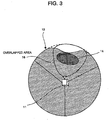
- Fig. 3 is a schematic diagram illustrating the cell in which the shrinkage phenomenon is compensated by another process of the adaptive antenna device in Fig. 1.
- the receiving radio unit 2 converts signals sent from a mobile station respectively received with plural receiving antenna elements 1 (Fig. 1) from the RF frequency band signals to the IF signals or baseband signals and then inputs them to the amplitude/phase controllers 31 in the baseband receiver 3.
- Each amplitude/phase controller 31 adds a predetermined weight obtained by the received signal processor 32 to the amplitude component and the phase component of a received signal and then outputs the weighted signal to the received signal processor 32.
- the received signal processor 32 respectively synthesizes the amplitude components and the phase components of weighted signals output from each amplitude/phase controllers 31, maximizes a received signal sent by a desired mobile station, and calculates the location of the desired mobile station (estimated arrival direction information) based on the synthesized value (vector).
- the corresponding received signal is merely selected.
- the received signal processor 32 calculates the weight of the amplitude component and the weight of the phase component of a signal received by each receiving antenna element 1 to bring to an optimum communication quality a signal from a desired mobile station of signals received by the plural receiving antenna elements 1.
- the received signal processor 32 transmits the calculated weight value (the control signal) to the corresponding amplitude/phase controller 31.
- the received signal processor 32 outputs the synthesized/selected received signal to the decoding processor 33.
- the decoding processor 33 outputs decodes the received signal into user data and then outputs it to the signal processor (not shown).
- the storage 7 holds the information on the estimated direction of arrival of a mobile station, which is calculated by the received signal processor 32.
- the information on an estimated direction of arrival is calculated for each baseband receiver 3 (for each user).
- the storage 7 respectively stores sets of information on the estimated direction of arrival of all mobile station within a cell under the jurisdiction of a base station.
- the information on the estimated direction of arrival of each mobile station may be calculated in sector units shown in Fig. 4.
- the encoding processor 63 subjects received user data or management information to a predetermined encoding process, using an error correction code, and outputs the encoded signal to the transmission signal processor 62.
- the transmission signal processor 62 disassembles the encoded signal into signals for respective transmission antenna elements 4, using the estimated mobile-station arrival direction information calculated by the received signal processor 32, to optimize the communication quality to a mobile station to be transmitted. Then the transmission signal processor 62 transmits the disassembled signals to the corresponding amplitude/phase controllers 61, respectively. Moreover, the transmission signal processor 62 calculates the weights (control signals) of amplitude components and the weights (control signals) of phase components to be added to disassembled signals and transmits the control signals to the amplitude/phase controllers 61, together with to the disassembled signals.
- Each amplitude/phase controller 61 adds a weight to the signal obtained from the transmission signal processor 62 and then outputs the weighted signal to the transmission radio unit 5.
- the transmission radio unit 5 transmits user data or management information to a mobile station via the plural transmission antenna elements 4.
- the weights which are calculated by the transmission signal processor 16 based on the estimated arrival direction information calculated by the received signal processor 32, are respectively added to the amplitude/phase controllers 61 (which is processing the received signal from the mobile station) in the baseband transmitter 6.
- the weights which are calculated by the controller 8 based on estimate arrival direction information held in the storage 7, are respectively added to the amplitude/phase controllers 61 in the baseband transmitter 6.
- the transmission signal processor 62 switches the transmission path to input the amplitude/phase controller 61 corresponding to the weight (control signal) transmitted from the controller 8.
- the controller 8 calculates the density of mobile stations within the cell of its own station based on estimated arrival direction information for each mobile station held in the storage 7.
- the controller 8 estimates an area of a high mobile-station density, or an area where the shrinkage phenomenon develops. Then the controller 8 calculates weights to be sent to each amplitude/phase controller 61 to compensate deterioration of the communication quality of a cell identification channel or notice information channel to be transmitted toward the area.
- the controller 8 compensates the cell reduction area. That is, the controller 8 controls the directivity and transmission power of a transmission signal with the weight value supplied to each amplitude/phase controller 61 so as to enlarge the cell size in the direction of the high density area 14 (see the compensation area in Fig. 2). Such a process enables to restore the cell to the size of the original effective area 12 (shown with the dotted lines in Fig. 2). Consequently, because only the reduced area of a cell is compensated, the cell shrinkage phenomenon can be effectively overcome.
- two baseband transmitters 6 transmit management information such as a cell identification channel or a notice information channel, respectively.
- management information such as a cell identification channel or a notice information channel
- the controller 8 transmits the cell identification channel or the notice information channel in an overlapped mode, in the cell reduction direction, using other baseband transmitter 3 (see the overlapped area 16 in Fig. 3).
- the transmission signal to be transmitted has the same information as that in the cell identification channel or in the notice information channel previously transmitted and is set to the same phase.
- the present invention with the configuration described above has the following advantages.
- the amplitude component and the phase component of a signal transmitted by a mobile station are respectively controlled to obtain an optimum communication quality thereof.
- Estimated arrival direction information being a result of estimating the direction of arrival of radio waves sent out by a mobile station is calculated for each of all mobile stations within a cell.
- the base station density is calculated based on the estimated arrival direction information calculated for each mobile station.
- the directivity of a transmission signal and the transmission power thereof are controlled to compensate the cell shrinkage phenomenon in an area of a high mobile station density. By doing so, the cell reduced area can be restored to the original effective area so that the cell shrinkage phenomenon can be effectively compensated.
Landscapes
- Engineering & Computer Science (AREA)
- Computer Networks & Wireless Communication (AREA)
- Signal Processing (AREA)
- Mobile Radio Communication Systems (AREA)
- Variable-Direction Aerials And Aerial Arrays (AREA)
Applications Claiming Priority (2)
| Application Number | Priority Date | Filing Date | Title |
|---|---|---|---|
| JP2001069030A JP2002271254A (ja) | 2001-03-12 | 2001-03-12 | 適応アンテナ装置及びその制御方法 |
| JP2001069030 | 2001-03-12 |
Publications (3)
| Publication Number | Publication Date |
|---|---|
| EP1241802A2 true EP1241802A2 (de) | 2002-09-18 |
| EP1241802A3 EP1241802A3 (de) | 2005-01-19 |
| EP1241802B1 EP1241802B1 (de) | 2007-01-03 |
Family
ID=18927125
Family Applications (1)
| Application Number | Title | Priority Date | Filing Date |
|---|---|---|---|
| EP20020005254 Expired - Lifetime EP1241802B1 (de) | 2001-03-12 | 2002-03-08 | Adaptive Antennenvorrichtung und dazugehöriges Steuerungsverfahren |
Country Status (3)
| Country | Link |
|---|---|
| EP (1) | EP1241802B1 (de) |
| JP (1) | JP2002271254A (de) |
| DE (1) | DE60217207T2 (de) |
Cited By (2)
| Publication number | Priority date | Publication date | Assignee | Title |
|---|---|---|---|---|
| CN102572861A (zh) * | 2011-12-13 | 2012-07-11 | 北京邮电大学 | 基于极化分集增益最优的基站变极化方法 |
| EP1698071B1 (de) * | 2003-12-16 | 2017-07-12 | Google, Inc. | Justierung eines signals in einem diversity-system |
Families Citing this family (3)
| Publication number | Priority date | Publication date | Assignee | Title |
|---|---|---|---|---|
| US8554686B2 (en) * | 2005-06-30 | 2013-10-08 | Advanced Micro Devices, Inc. | Anti-hack protection to restrict installation of operating systems and other software |
| JP5033731B2 (ja) * | 2008-07-29 | 2012-09-26 | 京セラ株式会社 | 無線基地局および無線通信方法 |
| JP5647663B2 (ja) * | 2012-11-30 | 2015-01-07 | ソフトバンクモバイル株式会社 | フェムトセル基地局、出力制御方法、及び出力制御プログラム |
Family Cites Families (4)
| Publication number | Priority date | Publication date | Assignee | Title |
|---|---|---|---|---|
| US5890067A (en) * | 1996-06-26 | 1999-03-30 | Bnr Inc. | Multi-beam antenna arrays for base stations in which the channel follows the mobile unit |
| US5945948A (en) * | 1996-09-03 | 1999-08-31 | Motorola, Inc. | Method and apparatus for location finding in a communication system |
| FI103629B1 (fi) * | 1996-10-10 | 1999-07-30 | Nokia Telecommunications Oy | Menetelmä puheluliikenteen kuuman pisteen määrittämiseksi solukkomatkaviestinjärjestelmän solussa |
| US6615024B1 (en) * | 1998-05-01 | 2003-09-02 | Arraycomm, Inc. | Method and apparatus for determining signatures for calibrating a communication station having an antenna array |
-
2001
- 2001-03-12 JP JP2001069030A patent/JP2002271254A/ja active Pending
-
2002
- 2002-03-08 DE DE2002617207 patent/DE60217207T2/de not_active Expired - Fee Related
- 2002-03-08 EP EP20020005254 patent/EP1241802B1/de not_active Expired - Lifetime
Cited By (3)
| Publication number | Priority date | Publication date | Assignee | Title |
|---|---|---|---|---|
| EP1698071B1 (de) * | 2003-12-16 | 2017-07-12 | Google, Inc. | Justierung eines signals in einem diversity-system |
| CN102572861A (zh) * | 2011-12-13 | 2012-07-11 | 北京邮电大学 | 基于极化分集增益最优的基站变极化方法 |
| CN102572861B (zh) * | 2011-12-13 | 2014-09-03 | 北京邮电大学 | 基于极化分集增益最优的基站变极化方法 |
Also Published As
| Publication number | Publication date |
|---|---|
| JP2002271254A (ja) | 2002-09-20 |
| EP1241802B1 (de) | 2007-01-03 |
| DE60217207D1 (de) | 2007-02-15 |
| DE60217207T2 (de) | 2007-05-03 |
| EP1241802A3 (de) | 2005-01-19 |
Similar Documents
| Publication | Publication Date | Title |
|---|---|---|
| CA2141733C (en) | Mobile telecommunication system | |
| US6917820B2 (en) | Method and apparatus for selection and use of optimal antennas in wireless systems | |
| US6754473B1 (en) | Apparatus and method for providing closed-loop transmit antenna diversity in a mobile communication system | |
| US7096041B2 (en) | Beam forming method | |
| US6108323A (en) | Method and system for operating a CDMA cellular system having beamforming antennas | |
| EP1092273B1 (de) | Nachrichtensystem für senden und demodulation eines nachrichtensignals mit einer adaptiven antennengruppe | |
| EP1033819B1 (de) | Basisstation und übertragungsverfahren | |
| US6353601B1 (en) | Method for selecting a signal, and a cellular radio system | |
| US5719583A (en) | Mobile communication system which performs antenna gain control | |
| US20040235433A1 (en) | Determining transmit diversity order and branches | |
| US7020445B1 (en) | Wireless base station system, and wireless transmission method | |
| KR19990082079A (ko) | 선택된 다중 다이버시티 수신을 이용한 셀룰러 무선전화 기지국의 방법 및 장치 | |
| US20020160778A1 (en) | Base station apparatus and handover control method | |
| WO1995034997A2 (en) | Diversity combining for antennas | |
| EP1487140B1 (de) | Funkendgerät, senderichtungssteuerverfahren und senderichtungssteuerprogramm | |
| JP2002503412A (ja) | 信頼距離帯域幅低減のための制御を採用している無線通信用の方法及び装置 | |
| KR20060121965A (ko) | 스위칭 빔 안테나 시스템에서의 빔 스위칭의 과도한임펙트를 감소시키는 방법 및 장치 | |
| EP1496627B1 (de) | Funkgerät, sende-/empfangs-gerichtetheitssteuerverfahren und sende-empfangsgerichtetheitssteuerprogramm | |
| JPH10503891A (ja) | セルラー無線システムにおける接続の質を改善する方法及びベースステーション | |
| EP1241802B1 (de) | Adaptive Antennenvorrichtung und dazugehöriges Steuerungsverfahren | |
| WO2004082173A1 (ja) | 送信ビーム制御方法、適応アンテナ送受信装置及び無線基地局 | |
| WO2006018365A1 (en) | Mobile radio communication system for downlink transmission and method for transmitting a signal across at least two downlink paths of a multiple antenna mobile radio communication system | |
| US7308036B2 (en) | Adaptive symbol mapping in mobile system | |
| US20040192389A1 (en) | Array antenna system in mobile communication | |
| US6487245B1 (en) | Method for testing a radiocommunications network, corresponding device and base station |
Legal Events
| Date | Code | Title | Description |
|---|---|---|---|
| PUAI | Public reference made under article 153(3) epc to a published international application that has entered the european phase |
Free format text: ORIGINAL CODE: 0009012 |
|
| AK | Designated contracting states |
Kind code of ref document: A2 Designated state(s): AT BE CH CY DE DK ES FI FR GB GR IE IT LI LU MC NL PT SE TR |
|
| AX | Request for extension of the european patent |
Free format text: AL;LT;LV;MK;RO;SI |
|
| PUAL | Search report despatched |
Free format text: ORIGINAL CODE: 0009013 |
|
| AK | Designated contracting states |
Kind code of ref document: A3 Designated state(s): AT BE CH CY DE DK ES FI FR GB GR IE IT LI LU MC NL PT SE TR |
|
| AX | Request for extension of the european patent |
Extension state: AL LT LV MK RO SI |
|
| RIC1 | Information provided on ipc code assigned before grant |
Ipc: 7H 04B 7/005 B Ipc: 7H 04B 7/06 B Ipc: 7H 04B 7/08 A Ipc: 7H 04Q 7/36 B |
|
| 17P | Request for examination filed |
Effective date: 20041210 |
|
| 17Q | First examination report despatched |
Effective date: 20050705 |
|
| AKX | Designation fees paid |
Designated state(s): DE FI GB SE |
|
| GRAP | Despatch of communication of intention to grant a patent |
Free format text: ORIGINAL CODE: EPIDOSNIGR1 |
|
| GRAS | Grant fee paid |
Free format text: ORIGINAL CODE: EPIDOSNIGR3 |
|
| GRAA | (expected) grant |
Free format text: ORIGINAL CODE: 0009210 |
|
| AK | Designated contracting states |
Kind code of ref document: B1 Designated state(s): DE FI GB SE |
|
| REG | Reference to a national code |
Ref country code: GB Ref legal event code: FG4D |
|
| REF | Corresponds to: |
Ref document number: 60217207 Country of ref document: DE Date of ref document: 20070215 Kind code of ref document: P |
|
| REG | Reference to a national code |
Ref country code: SE Ref legal event code: TRGR |
|
| PLBE | No opposition filed within time limit |
Free format text: ORIGINAL CODE: 0009261 |
|
| STAA | Information on the status of an ep patent application or granted ep patent |
Free format text: STATUS: NO OPPOSITION FILED WITHIN TIME LIMIT |
|
| 26N | No opposition filed |
Effective date: 20071005 |
|
| PGFP | Annual fee paid to national office [announced via postgrant information from national office to epo] |
Ref country code: FI Payment date: 20090316 Year of fee payment: 8 |
|
| PGFP | Annual fee paid to national office [announced via postgrant information from national office to epo] |
Ref country code: GB Payment date: 20090304 Year of fee payment: 8 |
|
| PGFP | Annual fee paid to national office [announced via postgrant information from national office to epo] |
Ref country code: DE Payment date: 20090306 Year of fee payment: 8 Ref country code: SE Payment date: 20090306 Year of fee payment: 8 |
|
| EUG | Se: european patent has lapsed | ||
| GBPC | Gb: european patent ceased through non-payment of renewal fee |
Effective date: 20100308 |
|
| PG25 | Lapsed in a contracting state [announced via postgrant information from national office to epo] |
Ref country code: FI Free format text: LAPSE BECAUSE OF NON-PAYMENT OF DUE FEES Effective date: 20100308 |
|
| PG25 | Lapsed in a contracting state [announced via postgrant information from national office to epo] |
Ref country code: DE Free format text: LAPSE BECAUSE OF NON-PAYMENT OF DUE FEES Effective date: 20101001 |
|
| PG25 | Lapsed in a contracting state [announced via postgrant information from national office to epo] |
Ref country code: GB Free format text: LAPSE BECAUSE OF NON-PAYMENT OF DUE FEES Effective date: 20100308 |
|
| PG25 | Lapsed in a contracting state [announced via postgrant information from national office to epo] |
Ref country code: SE Free format text: LAPSE BECAUSE OF NON-PAYMENT OF DUE FEES Effective date: 20100309 |