EP1241491A1 - Fibre optique photonique à double gaine - Google Patents
Fibre optique photonique à double gaine Download PDFInfo
- Publication number
- EP1241491A1 EP1241491A1 EP02290420A EP02290420A EP1241491A1 EP 1241491 A1 EP1241491 A1 EP 1241491A1 EP 02290420 A EP02290420 A EP 02290420A EP 02290420 A EP02290420 A EP 02290420A EP 1241491 A1 EP1241491 A1 EP 1241491A1
- Authority
- EP
- European Patent Office
- Prior art keywords
- fiber
- sheath
- holes
- core
- index
- Prior art date
- Legal status (The legal status is an assumption and is not a legal conclusion. Google has not performed a legal analysis and makes no representation as to the accuracy of the status listed.)
- Granted
Links
- 239000013307 optical fiber Substances 0.000 title claims abstract description 7
- 238000005253 cladding Methods 0.000 title abstract description 6
- 239000000835 fiber Substances 0.000 claims abstract description 173
- 229910052761 rare earth metal Inorganic materials 0.000 claims abstract description 5
- 239000011159 matrix material Substances 0.000 claims description 17
- 230000003321 amplification Effects 0.000 abstract description 9
- 238000003199 nucleic acid amplification method Methods 0.000 abstract description 9
- 238000011084 recovery Methods 0.000 abstract description 7
- 230000003287 optical effect Effects 0.000 abstract description 6
- 230000000694 effects Effects 0.000 description 12
- VYPSYNLAJGMNEJ-UHFFFAOYSA-N Silicium dioxide Chemical compound O=[Si]=O VYPSYNLAJGMNEJ-UHFFFAOYSA-N 0.000 description 8
- 239000006185 dispersion Substances 0.000 description 8
- 238000009826 distribution Methods 0.000 description 8
- 229910052769 Ytterbium Inorganic materials 0.000 description 5
- 239000000463 material Substances 0.000 description 5
- NAWDYIZEMPQZHO-UHFFFAOYSA-N ytterbium Chemical compound [Yb] NAWDYIZEMPQZHO-UHFFFAOYSA-N 0.000 description 5
- 229910052691 Erbium Inorganic materials 0.000 description 4
- UYAHIZSMUZPPFV-UHFFFAOYSA-N erbium Chemical compound [Er] UYAHIZSMUZPPFV-UHFFFAOYSA-N 0.000 description 4
- 239000000377 silicon dioxide Substances 0.000 description 4
- 239000002019 doping agent Substances 0.000 description 2
- 230000006870 function Effects 0.000 description 2
- 208000025339 heart septal defect Diseases 0.000 description 2
- 238000004519 manufacturing process Methods 0.000 description 2
- 238000000034 method Methods 0.000 description 2
- 230000010287 polarization Effects 0.000 description 2
- 238000005086 pumping Methods 0.000 description 2
- 229910052684 Cerium Inorganic materials 0.000 description 1
- OAICVXFJPJFONN-UHFFFAOYSA-N Phosphorus Chemical compound [P] OAICVXFJPJFONN-UHFFFAOYSA-N 0.000 description 1
- 229920000297 Rayon Polymers 0.000 description 1
- 241000220317 Rosa Species 0.000 description 1
- 230000002730 additional effect Effects 0.000 description 1
- XAGFODPZIPBFFR-UHFFFAOYSA-N aluminium Chemical compound [Al] XAGFODPZIPBFFR-UHFFFAOYSA-N 0.000 description 1
- 229910052782 aluminium Inorganic materials 0.000 description 1
- 230000000712 assembly Effects 0.000 description 1
- 238000000429 assembly Methods 0.000 description 1
- 230000005540 biological transmission Effects 0.000 description 1
- GWXLDORMOJMVQZ-UHFFFAOYSA-N cerium Chemical compound [Ce] GWXLDORMOJMVQZ-UHFFFAOYSA-N 0.000 description 1
- 239000012141 concentrate Substances 0.000 description 1
- 239000002657 fibrous material Substances 0.000 description 1
- 229910052732 germanium Inorganic materials 0.000 description 1
- GNPVGFCGXDBREM-UHFFFAOYSA-N germanium atom Chemical compound [Ge] GNPVGFCGXDBREM-UHFFFAOYSA-N 0.000 description 1
- 230000006872 improvement Effects 0.000 description 1
- 230000004048 modification Effects 0.000 description 1
- 238000012986 modification Methods 0.000 description 1
- 229910052698 phosphorus Inorganic materials 0.000 description 1
- 239000011574 phosphorus Substances 0.000 description 1
- 239000004038 photonic crystal Substances 0.000 description 1
- 230000008569 process Effects 0.000 description 1
- 230000001902 propagating effect Effects 0.000 description 1
- 150000002910 rare earth metals Chemical class 0.000 description 1
- 239000002964 rayon Substances 0.000 description 1
- 239000011343 solid material Substances 0.000 description 1
- 230000003595 spectral effect Effects 0.000 description 1
- 230000007480 spreading Effects 0.000 description 1
- 238000003892 spreading Methods 0.000 description 1
Images






Classifications
-
- G—PHYSICS
- G02—OPTICS
- G02B—OPTICAL ELEMENTS, SYSTEMS OR APPARATUS
- G02B6/00—Light guides; Structural details of arrangements comprising light guides and other optical elements, e.g. couplings
- G02B6/02—Optical fibres with cladding with or without a coating
- G02B6/02295—Microstructured optical fibre
- G02B6/02314—Plurality of longitudinal structures extending along optical fibre axis, e.g. holes
- G02B6/02319—Plurality of longitudinal structures extending along optical fibre axis, e.g. holes characterised by core or core-cladding interface features
- G02B6/02333—Core having higher refractive index than cladding, e.g. solid core, effective index guiding
-
- B—PERFORMING OPERATIONS; TRANSPORTING
- B82—NANOTECHNOLOGY
- B82Y—SPECIFIC USES OR APPLICATIONS OF NANOSTRUCTURES; MEASUREMENT OR ANALYSIS OF NANOSTRUCTURES; MANUFACTURE OR TREATMENT OF NANOSTRUCTURES
- B82Y20/00—Nanooptics, e.g. quantum optics or photonic crystals
-
- G—PHYSICS
- G02—OPTICS
- G02B—OPTICAL ELEMENTS, SYSTEMS OR APPARATUS
- G02B6/00—Light guides; Structural details of arrangements comprising light guides and other optical elements, e.g. couplings
- G02B6/02—Optical fibres with cladding with or without a coating
- G02B6/02295—Microstructured optical fibre
- G02B6/02314—Plurality of longitudinal structures extending along optical fibre axis, e.g. holes
- G02B6/02319—Plurality of longitudinal structures extending along optical fibre axis, e.g. holes characterised by core or core-cladding interface features
- G02B6/02338—Structured core, e.g. core contains more than one material, non-constant refractive index distribution in core, asymmetric or non-circular elements in core unit, multiple cores, insertions between core and clad
-
- G—PHYSICS
- G02—OPTICS
- G02B—OPTICAL ELEMENTS, SYSTEMS OR APPARATUS
- G02B6/00—Light guides; Structural details of arrangements comprising light guides and other optical elements, e.g. couplings
- G02B6/02—Optical fibres with cladding with or without a coating
- G02B6/02295—Microstructured optical fibre
- G02B6/02314—Plurality of longitudinal structures extending along optical fibre axis, e.g. holes
- G02B6/02342—Plurality of longitudinal structures extending along optical fibre axis, e.g. holes characterised by cladding features, i.e. light confining region
- G02B6/02347—Longitudinal structures arranged to form a regular periodic lattice, e.g. triangular, square, honeycomb unit cell repeated throughout cladding
-
- H—ELECTRICITY
- H01—ELECTRIC ELEMENTS
- H01S—DEVICES USING THE PROCESS OF LIGHT AMPLIFICATION BY STIMULATED EMISSION OF RADIATION [LASER] TO AMPLIFY OR GENERATE LIGHT; DEVICES USING STIMULATED EMISSION OF ELECTROMAGNETIC RADIATION IN WAVE RANGES OTHER THAN OPTICAL
- H01S3/00—Lasers, i.e. devices using stimulated emission of electromagnetic radiation in the infrared, visible or ultraviolet wave range
- H01S3/05—Construction or shape of optical resonators; Accommodation of active medium therein; Shape of active medium
- H01S3/06—Construction or shape of active medium
- H01S3/063—Waveguide lasers, i.e. whereby the dimensions of the waveguide are of the order of the light wavelength
- H01S3/067—Fibre lasers
- H01S3/06708—Constructional details of the fibre, e.g. compositions, cross-section, shape or tapering
- H01S3/06716—Fibre compositions or doping with active elements
-
- H—ELECTRICITY
- H01—ELECTRIC ELEMENTS
- H01S—DEVICES USING THE PROCESS OF LIGHT AMPLIFICATION BY STIMULATED EMISSION OF RADIATION [LASER] TO AMPLIFY OR GENERATE LIGHT; DEVICES USING STIMULATED EMISSION OF ELECTROMAGNETIC RADIATION IN WAVE RANGES OTHER THAN OPTICAL
- H01S3/00—Lasers, i.e. devices using stimulated emission of electromagnetic radiation in the infrared, visible or ultraviolet wave range
- H01S3/05—Construction or shape of optical resonators; Accommodation of active medium therein; Shape of active medium
- H01S3/06—Construction or shape of active medium
- H01S3/063—Waveguide lasers, i.e. whereby the dimensions of the waveguide are of the order of the light wavelength
- H01S3/067—Fibre lasers
- H01S3/06708—Constructional details of the fibre, e.g. compositions, cross-section, shape or tapering
Definitions
- the present invention relates to the field of fiber transmissions optical, and more specifically, double clad photonic optical fibers used for optical signal amplification.
- the index profile is generally qualified in function of the shape of the graph of the function which associates with the radius of the fiber the index of refraction.
- These curves are generally representative of the theoretical or target profile of the fiber, the constraints of fiber manufacturing can lead to a significantly different profile.
- the variations in the index depending on the profile make it possible to control the propagation of the light along the fiber.
- photonic fibers also called in English language “photonic crystal fibers” (PCF): these fibers are not, like conventional fibers, entirely made of a transparent solid material such as doped silica; in section, a photonic fiber has a plurality of air holes. These holes are parallel to the axis of the fiber, and extend longitudinally along the fiber. In practice, these holes can be obtained by manufacturing the preform by assembly of capillary tubes or cylinders of silica, respecting the pattern of holes to be obtained in the fiber. The stretching of such a preform provides a fiber with holes corresponding to the capillary tubes.
- EP-A-1 043 816 describes a double-clad fiber; the signal is transmitted in the doped fiber core and a pump is injected into the first sheath; the second sheath has the effect of confining the light of the pump in the first sheath.
- regions of modified index in the first sheath may in particular consist of air holes.
- regions of modified index are planned, distributed over the periphery of the first sheath.
- six index regions are provided. modified, forming the vertices and midpoints of the sides of an equilateral triangle. It is suggested that the modified index regions should be arranged as far as possible from the core of the fiber, in order to avoid modifying the polarization in the core of the fiber.
- the problem of the invention is the improvement of the efficiency of the amplifiers double clad optics, compared to the solution proposed in EP-A-1 043 816.
- the invention therefore proposes, in one embodiment, a distribution of the holes in a double clad photonic fiber, not only in the first cladding, but also in the heart of the fiber.
- the fiber has a plurality of holes in the heart and in the first sheath.
- the mode diameter of a signal injected into the heart of fiber is greater than the diameter of the heart.
- the doping can extend in a disc, or in a crown.
- the crown preferably covers the interface between the fiber core and the first sheath.
- the holes can be arranged on a triangular dot matrix; we may not have a hole in the axis of the fiber. We can also foresee that the holes have an increasing dimension away from the axis of the fiber.
- the invention also provides an amplifier comprising such a fiber and at minus a pump injected into the first sheath. Finally, it offers a fiber laser comprising such a fiber and at least one pump injected into the first sheath.
- the invention proposes, in a double-clad fiber, to provide holes not only in the first sheath, but also in the core of the fiber; she permits thus improving the overlap between the signal and the pump.
- the proposed solution by the invention goes against the teaching of document EP-A-1 043 816, in which it is proposed to arrange the holes on the outside of the sheath.
- the solution proposed in this document aims to return to the fiber core the rays of pump light propagating in the vicinity of the interface between the first sheath and the second sheath.
- the solution proposed in the invention is based on a completely different technical effect: the holes in the sheath as in the heart have the effect of increasing the mode diameter of the signal and the overlap between the signal and the pump.
- the holes in the fiber are at least in the core of the fiber; the presence of holes has the effect of increasing the mode diameter of the injected signal in the heart of the fiber; in this way, the overlap between the signal and a pump injected into the sheath.
- Figure 1 shows a schematic representation of the section of a fiber photonic optics according to one embodiment of the invention
- the fiber 2 has a fiber core 4, a first sheath 6 surrounding the fiber core and a second sheath 8 surrounding the first sheath; the outer limit of this second sheath is not shown in the figure.
- These different parts of the fiber are defined in a manner known per se, by the difference in index between the heart and the first sheath, on the one hand, and by the difference in India between the first sheath and the second sheath on the other hand.
- the fiber core as the part of the fiber which extends in the center of the fiber, and which is limited by the interface with the first sheath, either by an index drop on the index profile.
- the first sheath is the part of the fiber that outside of this first interface and up to a second interface with the second sheath, i.e. up to a second fall of index on the index profile.
- the fiber of FIG. 1 is doped with at least one rare earth ion, having an atomic number between 57 and 71.
- erbium can be used, ytterbium, germanium or other elements well known as such for their use in optical amplifiers.
- a proportion of erbium of the order of 1000 ppm by mass is suitable for using the fiber as erbium-doped amplifier; co-doping with ytterbium can be provided, with ytterbium proportions from 5,000 to 20,000 ppm by mass.
- doping with ytterbium alone in a proportion which can be close to 2000 ppm.
- Pumping wavelengths are typically of the order of 970 to 985 nm in the case of doping with erbium and close to 915 nm for doping with ytterbium.
- the location of the rare earth doping in the fiber can vary depending on the embodiments; it is possible to only dop the core of the fiber; however, insofar as the presence of holes in the fiber has the effect of increasing the signal mode diameter beyond the fiber core, it may be advantageous for the doping also extends at least partially in the first sheath; this allows improve the amplification efficiency in the fiber.
- the fiber is a photonic fiber, i.e. has holes extending longitudinally. There is at least one hole in the fiber, and preferably more than one hole.
- the holes are arranged at least partly in the fiber core, and have the effect of increasing the signal mode diameter injected into the fiber core.
- the holes are arranged on the points of a triangular matrix; the term "matrix" qualifies the set of possible locations of holes in the photonic fiber; insofar as the fiber preform is formed by assembling tubes capillaries and full cylinders, this "matrix" is defined by the arrangement of the tubes and cylinders in the preform.
- the tubes and cylinders are arranged in rows, two adjacent rows being offset a distance corresponding to the distance between two adjacent tubes or cylinders in the row.
- Other matrix forms are possible - for example a matrix square.
- the matrix is formed by a set of points, in which it is possible if necessary to provide a hole.
- the holes are arranged in the matrix triangular, following a hexagon; there is no hole in the center of the fiber.
- the distribution of holes in the fiber may vary from this example.
- the holes can extend only in the core of the fiber, as in the examples of FIGS. 7 and 13. They thus make it possible to increase the diameter of the core while remaining single-mode for the signal, which then makes it possible to increase the mode diameter.
- the fiber would not be not necessarily single mode in the absence of holes.
- the presence of the holes allows to converse a monomode behavior, even for strong rays of heart.
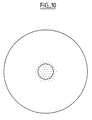
- the holes can also extend in the first sheath, as in the example of Figure 1 or that of Figures 4 and 10. In this case, they can extend fairly widely in the first sheath, as in the example of the Figure 1, or simply in the vicinity of the single-mode core, as in the case of Figures 4 and 10.
- the variant of Figure 1 is particularly interesting when the outermost holes have a confining effect on the signal, or a additional effect of redirection of the pump light towards the fiber core.
- layer a subset of the matrix of points, which in section, respects as much as possible a symmetry by rotation around the center of the fiber. Successive layers are concentric, with the fiber center as the common center.
- a layer is typically formed of a set of holes arranged on the vertices and if necessary the sides of a hexagon; the first one layer has six points arranged on the vertices of a hexagon whose center is the center of the fiber; in the example given in this request, are provided holes for all the points of this layer.
- the second layer is formed of twelve points, arranged on the vertices and in the middle of the sides of a regular hexagon; the length of one side of this hexagon is twice the length of the side of the hexagon forming the first layer; in the example of this patent application, holes are also provided for all the points of this layer.
- the third layer is formed by twenty-four points, distributed on the vertices of a hexagon, and one-third and two-thirds on each side; there are no holes on the third layer.
- each layer is invariant by rotation of angle 60 ° around the center of the fiber; each layer therefore constitutes an approximation of a circle, using the possible points of the matrix.
- a layer is generalized to others types of matrices. So, for a square matrix, a layer could be formed a set of points arranged on the edges of a square or an octagon; a layer would then be invariant by 90 ° angle rotation around the center of the fiber.
- the document W.J. Wadsworth and others cited above presents two "periods” of holes surrounding the center of the fiber; each "period” is circular.
- the holes in the fiber have as much as possible radial symmetry, taking into account the geometric constraints imposed by the matrix points; This ensures that the polarization of the signal is not or only slightly disturbed by the presence of holes in the fiber.
- the holes have dimensions variables. At least one layer can be provided without holes; this layer has the effect allow the field to spread in the fiber and thus increase its surface effective and therefore increase its mode diameter.
- holes have a radially increasing dimension: in other words, the holes of a layer are larger than the holes on a layer more interior. This radial increase in the dimensions of the holes allows improve the confining effect of light inside the fiber; indeed, qualitatively, larger holes correspond to a drop larger of the average index, and we can consider that a hole layer forms a sort of index jump, with an even greater variation in index of the hole size varies.
- the holes in the fiber of FIG. 1 are circular and have a diameter of 0.5 ⁇ m; the distance between the holes in the matrix is 5 ⁇ m; the hole distribution of figure 1 presents six layers, each layer having the shape of a hexagon.
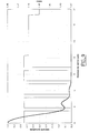
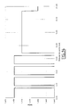
- Figure 2 shows the index profile of the fiber in Figure 1; conventionally, the distance to the center of the fiber has been plotted on the abscissa and the index of the material making up the fiber on the ordinate; it will be noted that the graph in FIG. 2 represents the index on a radius of the fiber, which passes through a vertex of the regular hexagon formed by the holes. We therefore see in the figure not only the index of the material, but the location of the holes, which is materialized by an index with a value of 1.
- FIG. 2 shows that the fiber core extends over a radius r 1 of 5 ⁇ m and has a difference in index ⁇ n 1 of 5.10 -3 relative to the index of the first cladding.
- the first sheath extends between the radii r 1 and r 2 , with r 2 being 40 ⁇ m; it has a difference in index ⁇ n 1 of 10.10 -3 compared to the index of the second sheath.
- the latter extends beyond this radius r 2 ; it may for example be non-doped silica.
- the figure also shows the drops in the index corresponding to the holes, at radii of 5, 10, 15, 20 and 25 ⁇ m.
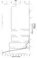
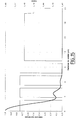
- Figure 3 shows a representation of the signal strength on a ray fiber of Figure 1; the radius is plotted on the abscissa, as in FIG. 2, and in ordinates the proportion of the signal intensity, in relation to the maximum intensity of the signal.
- the index profile has also been shown in FIG. 3, the indices being indicated in ordered on the right of the figure. It can be seen in the figure that the signal intensity keeps important values, well beyond the diameter of the fiber core; in example, the mode diameter is 11.5 ⁇ m (mode diameter at 1 / e, calculated from way known per se for a Gaussian approximation of the intensity).
- a fiber having a distribution of holes like the one proposed in the same day application would have a mode diameter of the order of 20 ⁇ m, for the same profile of the material index.
- the dopant used is erbium, in one proportion close to 1000 ppm.
- crown doping in the example between 9 and 16 ⁇ m; the lower bound is slightly less than the diameter of the heart singlemode, while the upper bound corresponds to the diameter of the circle in which we find 90% of energy.
- the invention makes it possible to improve the recovery, compared with a fiber to double sheath with no hole.
- a double fiber sheath with a circular sheath can have an overlap of around 1% for a single-mode core diameter of 8 ⁇ m and a first circular sheath of one 100 ⁇ m diameter.
- the presence of holes like proposed in the examples of this application increases the recovery, which can reach values of around 1.3%. The presence of holes ensures almost 30% increase in recovery.
- the fiber of figure 1 can be used in all assemblies amplification or laser known per se; co-directional pumping is possible or contra-directional, or both.
- Figures 4 to 6 are figures similar to Figures 1 to 3, for another fiber.
- the holes are distributed inside the single-mode core and on the part of the first sheath adjacent to this single-mode core.
- the holes have a diameter of 0.5 ⁇ m and are separated by a distance of 2.5 ⁇ m.
- the propagation characteristics of the fiber in Figure 4 are as follows; the fiber has at 1550 nm a chromatic dispersion of 3.41 ps / (nm.km), and a chromatic dispersion slope of 0.10 ps / (nm 2 .km). At this same wavelength, it has an effective surface of 55.4 ⁇ m 2 .
- Figures 7 to 9 are figures similar to Figures 1 to 3, for another fiber.
- the holes are only distributed inside the fiber core, according to a distribution similar to that of FIG. 1.
- the fiber core has a radius r 1 of 12.5 ⁇ m, a difference in index ⁇ n 1 of 4.5.10 -3 relative to the index of the first sheath; the first sheath extends to a radius r 2 of 20 ⁇ m and has a difference in index ⁇ n 2 of 10.10 -3 compared to the index of the second sheath.
- the mode diameter of the signal is 9 ⁇ m, and is greater than the mode diameter of the fiber in Figure 4.
- the propagation characteristics of the fiber in FIG. 7 are as follows: the fiber has a chromatic dispersion of 8.50 ps / (nm.km) at 1550 nm, and a chromatic dispersion slope of -2.8 ps / ( nm 2 .km). At this same wavelength, it has an effective surface of 63.5 ⁇ m 2 .
- Figures 10 to 12 are figures similar to Figures 1 to 3, for a third fiber.
- the holes are distributed as in Figure 1, but the core radius is larger; the holes are however distributed, as in FIG. 1 in the core and in the sheath.
- the index profile of FIG. 11 differs from that of FIG. 5 in that the fiber core has a radius r 1 of 7.5 ⁇ m.
- the signal mode diameter is still 9 ⁇ m
- the propagation characteristics of the fiber in FIG. 10 are as follows: the fiber has a chromatic dispersion of 5.0 ps / (nm.km) at 1550 nm, and a chromatic dispersion slope of -0.11 ps / ( nm 2 .km). At this same wavelength, it has an effective surface of 61.1 ⁇ m 2 .
- Figures 13 to 15 are figures similar to Figures 1 to 3, for a fourth fiber.
- the holes are distributed as in Figure 4, but the core radius is larger; the holes are distributed throughout the fiber core, without however extending into the first sheath.
- the index profile of FIG. 14 differs from that of FIG. 5 in that the fiber core has a radius r 1 of 10 ⁇ m.
- the signal mode diameter is 9 ⁇ m.
- the propagation characteristics of the fiber in FIG. 13 are as follows: the fiber has a chromatic dispersion of 5.79 ps / (nm.km) at 1550 nm, and a chromatic dispersion slope of 0.11 ps / (nm 2 .km). At this same wavelength, it has an effective surface of 63.4 ⁇ m 2 .
- the fibers described above are advantageously used as fibers amplification in optical amplifiers. Compared to double fibers conventional sheath, they have better signal and pump recovery, and provide better amplification efficiency. Typically, the yield amplification in a fiber like those described is 30% higher than amplification efficiency in a corresponding fiber of the state of the art.
- the holes of the different fibers are circular: we could also use holes of another shape.
- the outer sheath has little effect on the functioning of the fibers given in example; it can vary in index as in size.
Landscapes
- Physics & Mathematics (AREA)
- Optics & Photonics (AREA)
- Engineering & Computer Science (AREA)
- General Physics & Mathematics (AREA)
- Electromagnetism (AREA)
- Chemical & Material Sciences (AREA)
- Nanotechnology (AREA)
- Biophysics (AREA)
- Crystallography & Structural Chemistry (AREA)
- Life Sciences & Earth Sciences (AREA)
- Plasma & Fusion (AREA)
- Lasers (AREA)
- Optical Fibers, Optical Fiber Cores, And Optical Fiber Bundles (AREA)
- Glass Compositions (AREA)
- Optical Integrated Circuits (AREA)
Abstract
- un coeur de fibre (4), une première gaine (6) entourant le coeur de fibre et une deuxième gaine (8) entourant la première gaine,
- au moins un trou (10) dans le coeur de fibre; et
- un dopage avec un ion de terre rare, dans le coeur de la fibre, et le cas échéant dans la première gaine.
Description
- un coeur de fibre, une première gaine entourant le coeur de fibre et une deuxième gaine entourant la première gaine,
- au moins un trou dans le coeur de fibre; et
- un dopage avec un ion de terre rare, au moins dans le coeur de la fibre.
- figure 1, une représentation schématique de la section d'une fibre optique photonique selon un mode de réalisation de l'invention;
- figure 2, une représentation du profil d'indice de consigne de la fibre de la figure 1,
- figure 3, une représentation de l'intensité du signal sur un rayon de la fibre de la figure 1;
- figures 4 à 15, des figures similaires aux figures 1 à 3, pour d'autres fibres.
- les trous de la fibre sont disposés sur au moins deux couches concentriques de points de la matrice centrées sur le centre de la fibre;
- les trous de la fibre disposés sur une couche ont une même dimension et occupent l'ensemble des points de la couche;
- les trous de la fibre disposés sur au moins une couche présentent une dimension différente de la dimension des trous de la fibre disposés sur au moins une autre couche.
- r1 = 5 µm;
- Δn1 = 4,5.10-3;
- r2 = 25 µm;
- Δn2 = 30.10-3;
Claims (11)
- Une fibre optique photonique à double gaine (2), présentantun coeur de fibre (4), une première gaine (6) entourant le coeur de fibre et une deuxième gaine (8 ) entourant la première gaine,au moins un trou (10) dans le coeur de fibre; etun dopage avec un ion de terre rare, au moins dans le coeur de la fibre.
- La fibre de la revendication 1, caractérisée en ce qu'elle présente une pluralité de trous dans le coeur et dans la première gaine.
- La fibre de la revendication 1 ou 2, caractérisée en ce que le diamètre de mode d'un signal injecté dans le coeur de fibre est supérieur au diamètre du coeur.
- La fibre de la revendication 1, 2 ou 3, caractérisée en ce que le dopage s'étend dans un disque.
- La fibre de la revendication 1, 2 ou 3, caractérisée en ce que le dopage s'étend dans une couronne.
- La fibre de la revendication 5, caractérisée en ce que la couronne recouvre l'interface entre le coeur de fibre et la première gaine.
- La fibre de l'une des revendications 1 à 6, caractérisée en ce que les trous sont disposés sur une matrice de points triangulaire.
- La fibre de la revendication 7, caractérisée en ce qu'elle ne présente pas de trou en son axe.
- La fibre de l'une des revendications 1 à 8, caractérisée en ce que les trous présentent une dimension croissante en s'éloignant de l'axe de la fibre.
- Un amplificateur comprenant une fibre selon l'une des revendications 1 à 9 et au moins une pompe injectée dans la première gaine.
- Un laser à fibre comprenant une fibre selon l'une des revendications 1 à 9 et au moins une pompe injectée dans la première gaine.
Applications Claiming Priority (2)
| Application Number | Priority Date | Filing Date | Title |
|---|---|---|---|
| FR0103640A FR2822243B1 (fr) | 2001-03-16 | 2001-03-16 | Fibre optique photonique a double gaine |
| FR0103640 | 2001-03-16 |
Publications (2)
| Publication Number | Publication Date |
|---|---|
| EP1241491A1 true EP1241491A1 (fr) | 2002-09-18 |
| EP1241491B1 EP1241491B1 (fr) | 2008-11-12 |
Family
ID=8861242
Family Applications (1)
| Application Number | Title | Priority Date | Filing Date |
|---|---|---|---|
| EP02290420A Expired - Lifetime EP1241491B1 (fr) | 2001-03-16 | 2002-02-21 | Fibre optique photonique à double gaine |
Country Status (7)
| Country | Link |
|---|---|
| US (1) | US7283711B2 (fr) |
| EP (1) | EP1241491B1 (fr) |
| JP (1) | JP2002359420A (fr) |
| CN (1) | CN1209644C (fr) |
| AT (1) | ATE414287T1 (fr) |
| DE (1) | DE60229804D1 (fr) |
| FR (1) | FR2822243B1 (fr) |
Cited By (1)
| Publication number | Priority date | Publication date | Assignee | Title |
|---|---|---|---|---|
| WO2012069180A3 (fr) * | 2010-11-23 | 2012-10-11 | Fraunhofer-Gesellschaft Zur Förderung Der Angewandten Forschung E . V . | Fibre à double enveloppe structurée |
Families Citing this family (26)
| Publication number | Priority date | Publication date | Assignee | Title |
|---|---|---|---|---|
| EP1241744A1 (fr) * | 2001-03-12 | 2002-09-18 | Alcatel | Amplificateur à fibre optique à double gainage |
| EP1420276A1 (fr) * | 2002-11-15 | 2004-05-19 | Alcatel | Fibre optique à cristaux photoniques préservant la polarisation de la lumière |
| US6901197B2 (en) | 2003-01-13 | 2005-05-31 | Sumitomo Electric Industries, Ltd. | Microstructured optical fiber |
| FR2852154B1 (fr) * | 2003-03-04 | 2005-05-20 | Cit Alcatel | Fibre optique amplificatrice a anneau dope et amplificateur contenant une telle fibre |
| EP2469314B1 (fr) * | 2003-04-17 | 2015-07-29 | Nippon Telegraph And Telephone Corporation | Fibre optique monomodale aidée par trou |
| WO2005022237A1 (fr) * | 2003-08-27 | 2005-03-10 | Brother Kogyo Kabushiki Kaisha | Dispositif d'affichage pour le balayage de la retine |
| US7280730B2 (en) | 2004-01-16 | 2007-10-09 | Imra America, Inc. | Large core holey fibers |
| EP1782510A4 (fr) * | 2004-08-25 | 2010-04-07 | Kla Tencor Tech Corp | Source de lumiere a base d'un amplificateur de fibre servant a controler des semi-conducteurs |
| JP4561314B2 (ja) | 2004-10-28 | 2010-10-13 | 日立電線株式会社 | ファイバレーザ用光ファイバ、ファイバレーザ及びレーザ発振方法 |
| WO2006098313A1 (fr) * | 2005-03-15 | 2006-09-21 | Omron Corporation | Amplificateur optique et dispositif laser |
| JP5065008B2 (ja) * | 2005-03-18 | 2012-10-31 | 古河電気工業株式会社 | 光ファイバおよび導波路 |
| US7787729B2 (en) | 2005-05-20 | 2010-08-31 | Imra America, Inc. | Single mode propagation in fibers and rods with large leakage channels |
| US7450808B2 (en) * | 2005-07-08 | 2008-11-11 | Nuffern | Optical fiber article and methods of making |
| KR101530379B1 (ko) * | 2006-03-29 | 2015-06-22 | 삼성전자주식회사 | 다공성 글래스 템플릿을 이용한 실리콘 나노 와이어의제조방법 및 이에 의해 형성된 실리콘 나노 와이어를포함하는 소자 |
| US7301879B1 (en) | 2006-09-12 | 2007-11-27 | Hewlett-Packard Development Company, L.P. | Optical print head |
| US20080130100A1 (en) * | 2006-11-30 | 2008-06-05 | Northrop Grumman Corporation | High-efficiency, high-reliability fiber amplifier using engineered passband of photonic bandgap optical fiber |
| JP5250565B2 (ja) * | 2007-02-05 | 2013-07-31 | フルカワ エレクトリック ノース アメリカ インコーポレーテッド | 光ファイバの分割された利得ドーピング |
| US8755658B2 (en) * | 2007-02-15 | 2014-06-17 | Institut National D'optique | Archimedean-lattice microstructured optical fiber |
| CN100592114C (zh) * | 2007-05-11 | 2010-02-24 | 江苏大学 | 一种微结构保偏光纤 |
| CN101809475B (zh) | 2007-09-26 | 2013-04-24 | Imra美国公司 | 玻璃大芯径光纤 |
| US9001414B2 (en) * | 2008-11-28 | 2015-04-07 | Nkt Photonics A/S | Cladding-pumped optical waveguide |
| US20110162527A1 (en) * | 2010-01-07 | 2011-07-07 | Graham Gibson | Microstructured Fibre Frit |
| US8903214B2 (en) * | 2010-06-25 | 2014-12-02 | Nkt Photonics A/S | Large core area single mode optical fiber |
| EP2791719B1 (fr) * | 2011-12-13 | 2021-09-22 | OFS Fitel, LLC | Amplificateur multic ur à fibre dopée à l'erbium |
| US9025239B2 (en) * | 2011-12-13 | 2015-05-05 | Ofs Fitel, Llc | Multi-core erbium-doped fiber amplifier |
| CN103197372B (zh) * | 2013-04-12 | 2015-04-22 | 浙江工业大学 | 光子晶体光纤 |
Citations (3)
| Publication number | Priority date | Publication date | Assignee | Title |
|---|---|---|---|---|
| EP0905834A2 (fr) * | 1997-09-11 | 1999-03-31 | Lucent Technologies Inc. | Fibre optique à base de silice avec gaine intermédiaire ayant un faible index de réfraction |
| JP2000035521A (ja) * | 1998-05-07 | 2000-02-02 | Nippon Telegr & Teleph Corp <Ntt> | 光ファイバ |
| EP1043816A2 (fr) * | 1999-04-09 | 2000-10-11 | Lucent Technologies Inc. | Gaine pour fibres optiques et fibres optiques l'utilisant |
Family Cites Families (19)
| Publication number | Priority date | Publication date | Assignee | Title |
|---|---|---|---|---|
| US5155792A (en) * | 1991-06-27 | 1992-10-13 | Hughes Aircraft Company | Low index of refraction optical fiber with tubular core and/or cladding |
| GB2302183B (en) * | 1992-09-30 | 1997-10-22 | Asahi Chemical Ind | A multicore hollow optical fiber and a method for preparation thereof |
| JP2816097B2 (ja) * | 1994-07-27 | 1998-10-27 | 日立電線株式会社 | 希土類元素添加マルチコア光ファイバ、その製造方法、およびその光ファイバを利用した光増幅器 |
| US5802236A (en) * | 1997-02-14 | 1998-09-01 | Lucent Technologies Inc. | Article comprising a micro-structured optical fiber, and method of making such fiber |
| JPH1079543A (ja) * | 1996-09-03 | 1998-03-24 | Fujitsu Ltd | 希土類ドープ光ファイバ |
| US6115526A (en) * | 1997-03-27 | 2000-09-05 | Brown University Research Foundation | Ultra high numerical aperture high power optical fiber laser |
| GB9713422D0 (en) * | 1997-06-26 | 1997-08-27 | Secr Defence | Single mode optical fibre |
| US6097870A (en) * | 1999-05-17 | 2000-08-01 | Lucent Technologies Inc. | Article utilizing optical waveguides with anomalous dispersion at vis-nir wavelenghts |
| DK1118887T3 (da) | 2000-01-21 | 2007-03-05 | Sumitomo Electric Industries | Foton-krystalglasfiber (PCF) med flere kappelag |
| US6571045B2 (en) * | 2000-01-21 | 2003-05-27 | Sumitomo Electric Industries, Ltd. | Microstructured optical fiber |
| US6418258B1 (en) * | 2000-06-09 | 2002-07-09 | Gazillion Bits, Inc. | Microstructured optical fiber with improved transmission efficiency and durability |
| FR2811437A1 (fr) * | 2000-07-06 | 2002-01-11 | Cit Alcatel | Fibre optique a pompage par la gaine et procede de fabrication d'une telle fibre |
| US6792188B2 (en) * | 2000-07-21 | 2004-09-14 | Crystal Fibre A/S | Dispersion manipulating fiber |
| US6400877B1 (en) * | 2000-09-01 | 2002-06-04 | Sumitomo Electric Industries, Ltd. | Negative-dispersion optical fiber and optical transmission line incorporating the same |
| US6574408B2 (en) * | 2000-09-14 | 2003-06-03 | Universite De Liege | Monomode optical fibre |
| EP1191370A1 (fr) * | 2000-09-14 | 2002-03-27 | University Of Liege | Fibre optique monomode |
| JP2002289949A (ja) * | 2001-03-26 | 2002-10-04 | Sony Corp | 光ファイバ、光増幅発振装置、レーザ光発生装置、レーザディスプレイ装置およびカラーレーザディスプレイ装置 |
| JP2003114350A (ja) * | 2001-07-31 | 2003-04-18 | Furukawa Electric Co Ltd:The | 光ファイバ、光ファイバ部品および光伝送方法 |
| EP1482605B1 (fr) * | 2003-05-28 | 2007-04-04 | Fujikura Ltd. | Procédé pour l'excitation d'un amplificateur à fibre optique |
-
2001
- 2001-03-16 FR FR0103640A patent/FR2822243B1/fr not_active Expired - Fee Related
-
2002
- 2002-02-21 DE DE60229804T patent/DE60229804D1/de not_active Expired - Lifetime
- 2002-02-21 EP EP02290420A patent/EP1241491B1/fr not_active Expired - Lifetime
- 2002-02-21 AT AT02290420T patent/ATE414287T1/de not_active IP Right Cessation
- 2002-03-08 CN CN02106790.2A patent/CN1209644C/zh not_active Expired - Lifetime
- 2002-03-15 US US10/098,128 patent/US7283711B2/en not_active Expired - Lifetime
- 2002-03-15 JP JP2002071229A patent/JP2002359420A/ja active Pending
Patent Citations (3)
| Publication number | Priority date | Publication date | Assignee | Title |
|---|---|---|---|---|
| EP0905834A2 (fr) * | 1997-09-11 | 1999-03-31 | Lucent Technologies Inc. | Fibre optique à base de silice avec gaine intermédiaire ayant un faible index de réfraction |
| JP2000035521A (ja) * | 1998-05-07 | 2000-02-02 | Nippon Telegr & Teleph Corp <Ntt> | 光ファイバ |
| EP1043816A2 (fr) * | 1999-04-09 | 2000-10-11 | Lucent Technologies Inc. | Gaine pour fibres optiques et fibres optiques l'utilisant |
Non-Patent Citations (4)
| Title |
|---|
| CREGAN R F ET AL: "DISTRIBUTION OF SPONTANEOUS EMISSION FROM AN ER3+-DOPED PHOTONIC CRYSTAL FIBER", JOURNAL OF LIGHTWAVE TECHNOLOGY, IEEE. NEW YORK, US, vol. 17, no. 11, November 1999 (1999-11-01), pages 2138 - 2141, XP001033280, ISSN: 0733-8724 * |
| PATENT ABSTRACTS OF JAPAN vol. 2000, no. 05 14 September 2000 (2000-09-14) * |
| SONDERGAARD T: "PHOTONIC CRYSTAL DISTRIBUTED FEEDBACK FIBER LASERS WITH BRAGG GRATINGS", JOURNAL OF LIGHTWAVE TECHNOLOGY, IEEE. NEW YORK, US, vol. 18, no. 4, April 2000 (2000-04-01), pages 589 - 597, XP000989283, ISSN: 0733-8724 * |
| WADSWORTH ET.AL.: "Yb3+-doped photonic crystal fibre laser", ELECTRONICS LETTERS., vol. 36, no. 17, 17 August 2000 (2000-08-17), IEE STEVENAGE., GB, pages 1452 - 1454, XP006015581, ISSN: 0013-5194 * |
Cited By (4)
| Publication number | Priority date | Publication date | Assignee | Title |
|---|---|---|---|---|
| WO2012069180A3 (fr) * | 2010-11-23 | 2012-10-11 | Fraunhofer-Gesellschaft Zur Förderung Der Angewandten Forschung E . V . | Fibre à double enveloppe structurée |
| US20140010246A1 (en) * | 2010-11-23 | 2014-01-09 | Friedrich-Schiller-Universitaet Jena | Structured double-sheath fiber |
| US9065245B2 (en) | 2010-11-23 | 2015-06-23 | Fraunhofer-Gesellschaft Zur Foerderung Der Angewandten Forschung E.V. | Structured double-sheath fiber |
| EP4528343A3 (fr) * | 2010-11-23 | 2025-06-04 | Fraunhofer-Gesellschaft zur Förderung der angewandten Forschung e.V. | Fibre structurée à double gaine |
Also Published As
| Publication number | Publication date |
|---|---|
| US20020131742A1 (en) | 2002-09-19 |
| FR2822243B1 (fr) | 2003-06-20 |
| CN1375712A (zh) | 2002-10-23 |
| US7283711B2 (en) | 2007-10-16 |
| EP1241491B1 (fr) | 2008-11-12 |
| ATE414287T1 (de) | 2008-11-15 |
| CN1209644C (zh) | 2005-07-06 |
| JP2002359420A (ja) | 2002-12-13 |
| FR2822243A1 (fr) | 2002-09-20 |
| DE60229804D1 (de) | 2008-12-24 |
Similar Documents
| Publication | Publication Date | Title |
|---|---|---|
| EP1241491B1 (fr) | Fibre optique photonique à double gaine | |
| EP1241493B1 (fr) | Fibre optique photonique à grande surface effective | |
| EP1482606B1 (fr) | Fibre optique pour amplification ou pour émission laser | |
| EP1326105B1 (fr) | Coupleur optique pour pompe multimode | |
| EP1709715B1 (fr) | Fibre optique multimode | |
| EP2823342B1 (fr) | Dispositif de conversion du profil spatial transverse d'intensite d'un faisceau lumineux, utilisant de preference une fibre optique microstructuree | |
| EP1210751B1 (fr) | Fibre optique a pompage par la gaine et procede de fabrication d'une telle fibre | |
| EP2260549B1 (fr) | Système à fibre laser de forte puissance | |
| EP1735882B1 (fr) | Fibre optique a trous | |
| EP2702649B1 (fr) | Fibre optique monomode à triple gaine | |
| EP2337166A1 (fr) | Procédé de fabrication d'une fibre optique monomode à coeur dopé terres rares et fibre optique monomode à coeur dopé terres rares | |
| EP3649707B1 (fr) | Fibre amplificatrice légèrement multimode | |
| EP3286811B1 (fr) | Fibre optique monomode conçue pour compenser une variation d'indice de refraction liée aux effets thermiques et laser utilisant une telle fibre optique comme milieu amplificateur | |
| FR2829305A1 (fr) | Fibre optique double coeur avec anneau dope terre rare | |
| WO2008090279A2 (fr) | Fibre optique dopee a symetrie spatiale brisee | |
| FR3138531A1 (fr) | Fibre optique comportant un réseau de Bragg | |
| WO2014206975A1 (fr) | Composant optique à fibre |
Legal Events
| Date | Code | Title | Description |
|---|---|---|---|
| PUAI | Public reference made under article 153(3) epc to a published international application that has entered the european phase |
Free format text: ORIGINAL CODE: 0009012 |
|
| AK | Designated contracting states |
Kind code of ref document: A1 Designated state(s): AT BE CH CY DE DK ES FI FR GB GR IE IT LI LU MC NL PT SE TR |
|
| AX | Request for extension of the european patent |
Free format text: AL;LT;LV;MK;RO;SI |
|
| 17P | Request for examination filed |
Effective date: 20030318 |
|
| AKX | Designation fees paid |
Designated state(s): AT BE CH CY DE DK ES FI FR GB GR IE IT LI LU MC NL PT SE TR |
|
| RAP1 | Party data changed (applicant data changed or rights of an application transferred) |
Owner name: ALCATEL LUCENT |
|
| 17Q | First examination report despatched |
Effective date: 20071026 |
|
| GRAP | Despatch of communication of intention to grant a patent |
Free format text: ORIGINAL CODE: EPIDOSNIGR1 |
|
| RIC1 | Information provided on ipc code assigned before grant |
Ipc: G02B 6/02 20060101AFI20080526BHEP Ipc: H01S 3/067 20060101ALI20080526BHEP |
|
| GRAS | Grant fee paid |
Free format text: ORIGINAL CODE: EPIDOSNIGR3 |
|
| GRAA | (expected) grant |
Free format text: ORIGINAL CODE: 0009210 |
|
| AK | Designated contracting states |
Kind code of ref document: B1 Designated state(s): AT BE CH CY DE DK ES FI FR GB GR IE IT LI LU MC NL PT SE TR |
|
| REG | Reference to a national code |
Ref country code: GB Ref legal event code: FG4D Free format text: NOT ENGLISH |
|
| REG | Reference to a national code |
Ref country code: CH Ref legal event code: EP |
|
| REG | Reference to a national code |
Ref country code: IE Ref legal event code: FG4D Free format text: LANGUAGE OF EP DOCUMENT: FRENCH |
|
| REF | Corresponds to: |
Ref document number: 60229804 Country of ref document: DE Date of ref document: 20081224 Kind code of ref document: P |
|
| PG25 | Lapsed in a contracting state [announced via postgrant information from national office to epo] |
Ref country code: AT Free format text: LAPSE BECAUSE OF FAILURE TO SUBMIT A TRANSLATION OF THE DESCRIPTION OR TO PAY THE FEE WITHIN THE PRESCRIBED TIME-LIMIT Effective date: 20081112 Ref country code: ES Free format text: LAPSE BECAUSE OF FAILURE TO SUBMIT A TRANSLATION OF THE DESCRIPTION OR TO PAY THE FEE WITHIN THE PRESCRIBED TIME-LIMIT Effective date: 20090223 |
|
| NLV1 | Nl: lapsed or annulled due to failure to fulfill the requirements of art. 29p and 29m of the patents act | ||
| PG25 | Lapsed in a contracting state [announced via postgrant information from national office to epo] |
Ref country code: FI Free format text: LAPSE BECAUSE OF FAILURE TO SUBMIT A TRANSLATION OF THE DESCRIPTION OR TO PAY THE FEE WITHIN THE PRESCRIBED TIME-LIMIT Effective date: 20081112 Ref country code: NL Free format text: LAPSE BECAUSE OF FAILURE TO SUBMIT A TRANSLATION OF THE DESCRIPTION OR TO PAY THE FEE WITHIN THE PRESCRIBED TIME-LIMIT Effective date: 20081112 |
|
| REG | Reference to a national code |
Ref country code: IE Ref legal event code: FD4D |
|
| PG25 | Lapsed in a contracting state [announced via postgrant information from national office to epo] |
Ref country code: DK Free format text: LAPSE BECAUSE OF FAILURE TO SUBMIT A TRANSLATION OF THE DESCRIPTION OR TO PAY THE FEE WITHIN THE PRESCRIBED TIME-LIMIT Effective date: 20081112 Ref country code: IE Free format text: LAPSE BECAUSE OF FAILURE TO SUBMIT A TRANSLATION OF THE DESCRIPTION OR TO PAY THE FEE WITHIN THE PRESCRIBED TIME-LIMIT Effective date: 20081112 |
|
| BERE | Be: lapsed |
Owner name: ALCATEL LUCENT Effective date: 20090228 |
|
| PG25 | Lapsed in a contracting state [announced via postgrant information from national office to epo] |
Ref country code: PT Free format text: LAPSE BECAUSE OF FAILURE TO SUBMIT A TRANSLATION OF THE DESCRIPTION OR TO PAY THE FEE WITHIN THE PRESCRIBED TIME-LIMIT Effective date: 20090413 Ref country code: SE Free format text: LAPSE BECAUSE OF FAILURE TO SUBMIT A TRANSLATION OF THE DESCRIPTION OR TO PAY THE FEE WITHIN THE PRESCRIBED TIME-LIMIT Effective date: 20090212 |
|
| PLBE | No opposition filed within time limit |
Free format text: ORIGINAL CODE: 0009261 |
|
| STAA | Information on the status of an ep patent application or granted ep patent |
Free format text: STATUS: NO OPPOSITION FILED WITHIN TIME LIMIT |
|
| PG25 | Lapsed in a contracting state [announced via postgrant information from national office to epo] |
Ref country code: MC Free format text: LAPSE BECAUSE OF NON-PAYMENT OF DUE FEES Effective date: 20090228 |
|
| REG | Reference to a national code |
Ref country code: CH Ref legal event code: PL |
|
| 26N | No opposition filed |
Effective date: 20090813 |
|
| PG25 | Lapsed in a contracting state [announced via postgrant information from national office to epo] |
Ref country code: LI Free format text: LAPSE BECAUSE OF NON-PAYMENT OF DUE FEES Effective date: 20090228 Ref country code: CH Free format text: LAPSE BECAUSE OF NON-PAYMENT OF DUE FEES Effective date: 20090228 |
|
| PG25 | Lapsed in a contracting state [announced via postgrant information from national office to epo] |
Ref country code: BE Free format text: LAPSE BECAUSE OF NON-PAYMENT OF DUE FEES Effective date: 20090228 |
|
| PG25 | Lapsed in a contracting state [announced via postgrant information from national office to epo] |
Ref country code: GR Free format text: LAPSE BECAUSE OF FAILURE TO SUBMIT A TRANSLATION OF THE DESCRIPTION OR TO PAY THE FEE WITHIN THE PRESCRIBED TIME-LIMIT Effective date: 20090213 |
|
| PG25 | Lapsed in a contracting state [announced via postgrant information from national office to epo] |
Ref country code: IT Free format text: LAPSE BECAUSE OF FAILURE TO SUBMIT A TRANSLATION OF THE DESCRIPTION OR TO PAY THE FEE WITHIN THE PRESCRIBED TIME-LIMIT Effective date: 20081112 |
|
| PG25 | Lapsed in a contracting state [announced via postgrant information from national office to epo] |
Ref country code: LU Free format text: LAPSE BECAUSE OF NON-PAYMENT OF DUE FEES Effective date: 20090221 |
|
| PG25 | Lapsed in a contracting state [announced via postgrant information from national office to epo] |
Ref country code: TR Free format text: LAPSE BECAUSE OF FAILURE TO SUBMIT A TRANSLATION OF THE DESCRIPTION OR TO PAY THE FEE WITHIN THE PRESCRIBED TIME-LIMIT Effective date: 20081112 |
|
| PG25 | Lapsed in a contracting state [announced via postgrant information from national office to epo] |
Ref country code: CY Free format text: LAPSE BECAUSE OF FAILURE TO SUBMIT A TRANSLATION OF THE DESCRIPTION OR TO PAY THE FEE WITHIN THE PRESCRIBED TIME-LIMIT Effective date: 20081112 |
|
| REG | Reference to a national code |
Ref country code: FR Ref legal event code: GC Effective date: 20131018 |
|
| REG | Reference to a national code |
Ref country code: FR Ref legal event code: RG Effective date: 20141016 |
|
| REG | Reference to a national code |
Ref country code: FR Ref legal event code: PLFP Year of fee payment: 14 |
|
| REG | Reference to a national code |
Ref country code: FR Ref legal event code: CA Effective date: 20150521 |
|
| REG | Reference to a national code |
Ref country code: FR Ref legal event code: CA Effective date: 20150521 |
|
| REG | Reference to a national code |
Ref country code: FR Ref legal event code: PLFP Year of fee payment: 15 |
|
| REG | Reference to a national code |
Ref country code: FR Ref legal event code: PLFP Year of fee payment: 16 |
|
| PGFP | Annual fee paid to national office [announced via postgrant information from national office to epo] |
Ref country code: FR Payment date: 20170217 Year of fee payment: 16 |
|
| REG | Reference to a national code |
Ref country code: FR Ref legal event code: ST Effective date: 20181031 |
|
| PG25 | Lapsed in a contracting state [announced via postgrant information from national office to epo] |
Ref country code: FR Free format text: LAPSE BECAUSE OF NON-PAYMENT OF DUE FEES Effective date: 20180228 |
|
| REG | Reference to a national code |
Ref country code: GB Ref legal event code: 732E Free format text: REGISTERED BETWEEN 20190429 AND 20190502 |
|
| REG | Reference to a national code |
Ref country code: DE Ref legal event code: R082 Ref document number: 60229804 Country of ref document: DE Representative=s name: MENZIETTI WETZEL, DE Ref country code: DE Ref legal event code: R081 Ref document number: 60229804 Country of ref document: DE Owner name: PROVENANCE ASSET GROUP LLC, PITTSFORD, US Free format text: FORMER OWNER: ALCATEL LUCENT, PARIS, FR |
|
| PGFP | Annual fee paid to national office [announced via postgrant information from national office to epo] |
Ref country code: GB Payment date: 20210301 Year of fee payment: 20 Ref country code: DE Payment date: 20210322 Year of fee payment: 20 |
|
| REG | Reference to a national code |
Ref country code: DE Ref legal event code: R071 Ref document number: 60229804 Country of ref document: DE |
|
| REG | Reference to a national code |
Ref country code: GB Ref legal event code: PE20 Expiry date: 20220220 |
|
| PG25 | Lapsed in a contracting state [announced via postgrant information from national office to epo] |
Ref country code: GB Free format text: LAPSE BECAUSE OF EXPIRATION OF PROTECTION Effective date: 20220220 |