EP1241426B1 - Angled turbulator for use in heat exchangers - Google Patents
Angled turbulator for use in heat exchangers Download PDFInfo
- Publication number
- EP1241426B1 EP1241426B1 EP02005314A EP02005314A EP1241426B1 EP 1241426 B1 EP1241426 B1 EP 1241426B1 EP 02005314 A EP02005314 A EP 02005314A EP 02005314 A EP02005314 A EP 02005314A EP 1241426 B1 EP1241426 B1 EP 1241426B1
- Authority
- EP
- European Patent Office
- Prior art keywords
- crests
- valleys
- rows
- turbulator
- heat exchanger
- Prior art date
- Legal status (The legal status is an assumption and is not a legal conclusion. Google has not performed a legal analysis and makes no representation as to the accuracy of the status listed.)
- Expired - Fee Related
Links
Images


Classifications
-
- F—MECHANICAL ENGINEERING; LIGHTING; HEATING; WEAPONS; BLASTING
- F28—HEAT EXCHANGE IN GENERAL
- F28F—DETAILS OF HEAT-EXCHANGE AND HEAT-TRANSFER APPARATUS, OF GENERAL APPLICATION
- F28F3/00—Plate-like or laminated elements; Assemblies of plate-like or laminated elements
- F28F3/02—Elements or assemblies thereof with means for increasing heat-transfer area, e.g. with fins, with recesses, with corrugations
- F28F3/025—Elements or assemblies thereof with means for increasing heat-transfer area, e.g. with fins, with recesses, with corrugations the means being corrugated, plate-like elements
- F28F3/027—Elements or assemblies thereof with means for increasing heat-transfer area, e.g. with fins, with recesses, with corrugations the means being corrugated, plate-like elements with openings, e.g. louvered corrugated fins; Assemblies of corrugated strips
-
- F—MECHANICAL ENGINEERING; LIGHTING; HEATING; WEAPONS; BLASTING
- F28—HEAT EXCHANGE IN GENERAL
- F28D—HEAT-EXCHANGE APPARATUS, NOT PROVIDED FOR IN ANOTHER SUBCLASS, IN WHICH THE HEAT-EXCHANGE MEDIA DO NOT COME INTO DIRECT CONTACT
- F28D9/00—Heat-exchange apparatus having stationary plate-like or laminated conduit assemblies for both heat-exchange media, the media being in contact with different sides of a conduit wall
- F28D9/0012—Heat-exchange apparatus having stationary plate-like or laminated conduit assemblies for both heat-exchange media, the media being in contact with different sides of a conduit wall the apparatus having an annular form
-
- Y—GENERAL TAGGING OF NEW TECHNOLOGICAL DEVELOPMENTS; GENERAL TAGGING OF CROSS-SECTIONAL TECHNOLOGIES SPANNING OVER SEVERAL SECTIONS OF THE IPC; TECHNICAL SUBJECTS COVERED BY FORMER USPC CROSS-REFERENCE ART COLLECTIONS [XRACs] AND DIGESTS
- Y10—TECHNICAL SUBJECTS COVERED BY FORMER USPC
- Y10S—TECHNICAL SUBJECTS COVERED BY FORMER USPC CROSS-REFERENCE ART COLLECTIONS [XRACs] AND DIGESTS
- Y10S165/00—Heat exchange
- Y10S165/916—Oil cooler
Definitions
- the interfaces are perforated so that valleys in each row are in fluid communication with immediately adjacent crests and any immediately adjacent row and crests in each row are in fluid communication with immediately adjacent valleys in any immediately adjacent row.
- the valleys are arranged to define a first series of parallel channels at an acute angle to a line defined by the shortest distance between the flow inlet and the flow outlet.
- the crests are arranged to define a first series of parallel ridges at the acute angle to the line defined by the shortest distance between the flow inlet and the flow outlet.
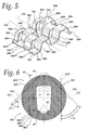
- Turbulators 60C and 60D are illustrated in Figs. 6 and 7, respectively.
- Each of the turbulators 60C and 60D comprises a sheet of material 62C having a good thermal conductivity, such as steel, copper, brass, or aluminum.
- the sheet 62C includes a plurality of strand-like rows 64C, as illustrated schematically by the dashed lines in Figs. 6 and 7, and as shown in Fig. 8.
- This offset creates windows or perforations 70C in the interfaces between immediately adjacent rows 64C so that the valleys 68C in each row 64C are in fluid communication with immediately adjacent crests 66C in any immediately adjacent row 64C and crests 66C in each row 64C are in fluid communication with any immediately adjacent valley 68C in any immediately adjacent row 64C.
- the valleys 68C are arranged to define a series of parallel channels 72C that are at an acute angle ⁇ with the rows 64C.
- the crests 66C are arranged to define a series of parallel ridges 74C that are also at the acute angle ⁇ with the row 64C.
- the angle ⁇ of the side walls 69C in the turbulator 60E runs in the direction of the angle ⁇ of the channels 72C and the ridges 74C, while the angle ⁇ of the side wall 69C in the turbulator 60F runs against the angle ⁇ of the channels 72C and the ridges 74C.
- rows 64C extend parallel to lines X defined by the shortest distance between the flow inlet 50 and the flow outlet 52 in Fig. 6 and between a flow inlet 80 and a flow outlet 82 in Figs. 7, 9, and 11.
- the relative position of the inlets 50, 80 and outlets 80, 82 for the turbulator 60A, 60C, 60D, 60E, and 60F can be switched so that the flow from the inlets 50, 80 is directed into the point of the herringbone pattern rather than into the bite of the herringbone pattern.
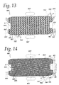
- a turbulator 60I made according to yet another embodiment of the invention, is illustrated in Fig. 14.
- the structural details of the turbulator 60I are a combination of selected structural details from the turbulators 60A and 60B shown in Figs. 3-5 and the turbulators 60C, 60D, and 60G shown in Figs. 6-8 and 12. More specifically, a plurality of groups 90I of rows 64A are provided in the turbulator 60I, with each group 90I consisting of ten rows 64A that when viewed as a group are structurally identical to the rows 64A described in connection with the turbulators 60A and 60B.
- a turbulator 60K made according to yet another embodiment of the invention is illustrated in Fig. 16.
- the structural details of the turbulator 60K are identical to the structural details of the turbulator 60I shown in Fig. 14, with the exceptions that a) groups 90K are formed from five rows 64C rather than ten rows 64C and b) the groups 90K are offset in a repeating back and forth staggered pattern to define a repeating herringbone pattern of the groups 90K, rather than in the progressive offset pattern of the groups 90I in the turbulator 60I.
- the turbulator 60H delivers relatively high heat transfers at a relatively high pressure drops in comparison to when the inlet 80H and the outlet 82H are used together with the turbulator 60H.
- the gross shape of the turbulators 60A, 60B, 60C, 60D, 60E, 60F, 60G, 60H, 60I, 60J, and 60K is dictated by the geometry of the heat exchange units 34 into which they are installed, and that the invention is not limited to the disclosed gross shapes.
- turbulators 60C, 60D, 60E, 60F, 60G, 60H, 60I, 60J, and 60K are provided. It should be understood that these dimensions may be used to define the turbulators 60A and 60B shown in Figs. 3-5.
- the dimension A is the amount of offset between one row 64C and an adjacent row 64C. As noted earlier, for the turbulators 60A and 60B, this offset is repeated back and forth from one row 64A to the next row 64A to create a staggered pattern best seen in Fig. 5, while for the turbulators 60C, 60D, 60E, 60F, and 60G the offset is progressive, with each subsequent row being offset in the same direction from the previous row as seen in Figs. 6-11.
- the dimension B defines the crest to crest pitch for each of the rows 64C.
- the dimension C defines a length for each of the crests 66C and for each of the valleys 68C.
- the dimension T defines the thickness of the sheet 62C.
- the dimension D defines the length of overlap between adjacent rows 64C.
- the dimension H defines the height of the turbulator 60C, 60D, 60E, 60F, and 60G.
- the dimension W defines the width to be consistent with length used to describe rows 64A at page 8, line 23, and rows 64C at page 10, line 19, and page 11, line 24.
- R indicates the inside radius of each of the crests 66C and the valleys 68C.
- the angles E are defined by the upward and downward slopes of each of the crests 66C and each of the valleys 68C, and preferably are equal in magnitude.
- the angle F is equal to 6° and defines the slope at the crown of each of the crests 66C and each of the valleys 68C. ( Figures shown in inches) A B C D H T R ùW .071" .281" .108" .033" .083" .010" .035" .058" 0,18034 [cm] 0,71374 [cm] 0,27432 [cm] 0,08382 [cm] 0,21082 [cm] 0,0254 [cm] 0,0889 [cm] 0,14732 [cm]
- the turbulators 60A, 60B, 60C, 60D, 60E, 60F, 60G, 60H, 60I, 60J, and 60K may be manufactured using known techniques.
- inventive turbulators can provide increased heat transfer performance at a given oil pressure drop, and a lower oil pressure drop at a given heat transfer rate. This increased performance will allow a heat exchanger having a fixed desired heat transfer capacity, such as an oil cooler, to be made with fewer heat exchange units, thereby reducing its cost, size, and weight.
Landscapes
- Engineering & Computer Science (AREA)
- Physics & Mathematics (AREA)
- Thermal Sciences (AREA)
- Mechanical Engineering (AREA)
- General Engineering & Computer Science (AREA)
- Heat-Exchange Devices With Radiators And Conduit Assemblies (AREA)
Description
- This invention relates to heat exchangers, and more particularly to heat exchangers of the type having a plurality of heat exchange units in stacked relation as used, for example, in oil coolers.
- It is known to provide the heat exchange units of heat exchangers with internal turbulators to improve the heat transfer characteristics of the heat exchanger. In general, the turbulators cause the fluid flowing through the heat exchange units to flow in a turbulent manner, thereby enhancing the heat transfer characteristics of the heat exchanger. Further, it is common for the turbulators to provide additional heat conductive paths through periodic contact points with the walls of the heat exchange units, thereby further increasing heat transfer within the heat exchanger.
- U.S. Patent Nos. 3,732,921 to Hillicki, et al.; 3,743,011 to Frost; 3,734,135 to Mosier; 3,763,930 to Frost; 4,360,055 to Frost; 4,561,494 to Frost; 4,967,835 to Lefeber; and 5,078,209 to Kerkman, et al. disclose heat exchangers having heat exchange units with turbulators therein. These heat exchangers have proven to be extremely successful, particularly in applications such as cooling the lubricating oil of an internal combustion engine. The disclosed structures are relatively simple in design, inexpensive to fabricate and readily serviceable when required. Nonetheless, there is a continuing desire to provide additional advantages in heat exchanger structures, including, for example, improved heat transfer characteristics, improved pressure drop characteristics, decreased weight and size, etc.
- The German utility model DE 296 22 191 U1 describes a heat exchanger with a turbulator in the flow chamber wherein this turbulator comprises rows of parallel straps which are displaced to each other and made by a wave-like sheet.
- It is the principal object of the invention to provide a new and improved turbulator for use in the heat exchange unit of heat exchangers, and more specifically, to provide a turbulator that increases the heat transfer capabilities of the heat exchanger and/or decreases the pressure drop through the heat exchanger, thereby allowing for reduction in the size and weight of a heat exchanger employing the turbulator.
- According to one facet of the invention, a lanced and offset turbulator for use in a heat exchanger is provided. The turbulator includes a sheet of material. The sheet includes a plurality of strand-like rows of alternating crests and valleys. The crests and valleys in each row are offset with respect to the crests and valleys in any immediately adjacent row. Each of the rows has an interface with any immediately adjacent row. The interfaces are perforated so that valleys in each row are in fluid communication with immediately adjacent crests in any immediately adjacent row and crests in each row are in fluid communication with any immediately adjacent valleys in any immediately adjacent row. The plurality of rows are divided into at least two groups which together define a herringbone pattern of the crests and valleys.
- According to one facet of the invention, all the rows are parallel to each other.
- According to one facet of the invention, the rows in one group of the at least two groups are at an acute angle with the rows of another group of the at least two groups of rows.
- According to one facet of the invention, a lanced and offset turbulator for use in a heat exchanger is provided. The turbulator includes a sheet of material. The sheet includes a plurality of strand-like rows of alternating crests and valleys. The crests and valleys in each row are offset with respect to the crests and valleys in any immediately adjacent row. Each of the rows has an interface with any immediately adjacent row. The interfaces are perforated so that valleys in each row are in fluid communication with immediately adjacent crests in any immediately adjacent row and crests in each row are in fluid communication with any immediately adjacent valleys in any immediately adjacent row. The valleys are arranged to define a first series of parallel channels at an acute angle with the rows, and the crests are arranged to define a first series of parallel ridges at the acute angle with the rows.
- According to another facet of the invention, the valleys are arranged to define a second series of parallel channels, the crests are arranged to define a second series of parallel ridges, and the first and second series of channels and ridges together define a herringbone pattern of the channels and ridges and the crests and valleys.
- In one embodiment, the invention is incorporated in a heat exchanger including a heat exchange unit. The heat exchange unit includes a first surface spaced generally parallel to a second surface to define a flow chamber, a flow inlet spaced from a flow outlet, and a generally planar lanced and offset turbulator in the flow chamber. The turbulator includes a sheet of material. The sheet has the plurality of strand-like rows of alternating crests and valleys, with the crests and valleys in each row being offset with respect to the crests and valleys in any immediately adjacent row. Each of the rows has an interface with any immediately adjacent row. The interfaces are perforated so that valleys in each row are in fluid communication with immediately adjacent crests and any immediately adjacent row and crests in each row are in fluid communication with immediately adjacent valleys in any immediately adjacent row. The valleys are arranged to define a first series of parallel channels at an acute angle to a line defined by the shortest distance between the flow inlet and the flow outlet. The crests are arranged to define a first series of parallel ridges at the acute angle to the line defined by the shortest distance between the flow inlet and the flow outlet.
- According to one facet of the invention, the first series of parallel channels and the first series of parallel ridges are perpendicular with the rows.
- According to one facet of the invention, the first series of parallel channels and the first series of parallel ridges are non-perpendicular with the rows.
- According to one facet of the invention, the rows are parallel to the line defined by the shortest distance between the flow inlet and the flow outlet.
- Other objects and advantages will become apparent from the following specification taken in connection with the accompanying drawings.
-
- Fig. 1 is a fragmentary, side elevation of an engine block having mounted thereon a heat exchanger in the form of an oil cooler employing turbulators embodying the invention, with a filter of the customary type in position superimposed on the oil cooler;
- Fig. 2 is an enlarged, fragmentary, sectional view of the heat exchanger shown in Fig. 1 with a portion of the oil filter shown in dotted lines;
- Fig. 3 is a plan view of a turbulator made according to one embodiment of the present invention;
- Fig. 4 is a plan view of a turbulator made according to a second embodiment of the invention;
- Fig. 5 is an enlarged perspective view of the area marked as 5-5 in Figs. 3 and 4;
- Fig. 6 is a plan view of a turbulator made according to a third embodiment of the invention;
- Fig. 7 is a plan view of a turbulator made according to a fourth embodiment of the invention with a portion broken away;
- Fig. 8 is an enlarged, partial sectional view taken along the lines 8-8 in Figs. 6 and 7;
- Fig. 9 is a plan view of a turbulator made according to a fifth embodiment of the invention;
- Fig. 10 is an enlarged, partial sectional view taken along the line 10-10 in Fig. 9;
- Fig. 11 is a plan view of a turbulator made according to a sixth embodiment of the invention;
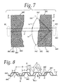
- Fig. 12 is a plan view of a turbulator made according to a seventh embodiment of the invention; and
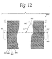
- Fig. 13 is a plan view of a turbulator made according to an eighth embodiment of the invention;
- Fig. 14 is a plan view of a turbulator made according to a ninth embodiment of the invention;
- Fig. 15 is a plan view of a turbulator made according to a tenth embodiment of the invention; and
- Fig. 16 is a plan view of a turbulator made according to an eleventh embodiment of the invention.
-
- Several exemplary embodiments of turbulators made according to the invention are described herein and are illustrated in the drawings in connection with an oil cooler for cooling the lubricating oil of an internal combustion engine. However, it should be understood that the invention may find utility in other applications and that no limitation to use as an oil cooler is intended except insofar as expressly stated in the appended claims.
- With reference to Fig. 1, the block of an internal combustion engine is fragmentarily shown at 10 and has received thereon an
oil cooler 12 for the lubricating oil for the engine. Anoil filter 14 is secured to theoil cooler 12 and the latter additionally has coolant inlet andoutlet lines oil cooler 12 via apassage 20 in theblock 10 and returning lubricating oil is received by the engine via apassage 22. - Turning to Fig. 2, the
passage 22 is defined by asleeve 24 fixedly attached to theengine block 10 and terminating in a threaded end 26 which in turn receives an internally threadedextender 28 inserted through a central opening in theoil cooler 12. Theextender 28 includes an externally threadedend 30 to which theoil filter 14 is connected in a conventional fashion. Theoil cooler 12 includes ahousing 32 and a plurality of heat exchange units, each generally designated 34, stacked within thehousing 32 and held in place by two spacedheader plates housing 32. - Referring to the heat exchange units 34, each is identical to the other and includes a
metal top plate 40 and a metal bottom plate 42. Each of thetop plates 40 is spaced generally parallel to the bottom plates 42 to define aflow chamber 43 in each of the heat exchange units 34. The heat exchange units 34 are generally circular and have an outer peripheral edge, shown generally at 44 that is defined by the outer edges of theplates 40, 42 which are clinched and/or brazed together. Additionally, each of the heat exchange units 34 includes aflow inlet 50, aflow outlet 52 and an inner seal joint 54 that surrounds the threadedextender 28. The flow inlets 50 are spaced on the opposite sides of thejoints 54 from theflow outlets 52. Each of the heat exchange units 34 further includes a planar, disc-like turbulator, generally designated 60, several embodiments of which will be described in greater detail hereinafter, disposed between the top andbottom plates 40, 42 within theflow chamber 43. Further description of the structural details of the oil cooler depicted is not necessary to understand the present invention, as it will be appreciated that a) the invention may be incorporated in any heat exchanger utilizing heat exchange units that define a flow path between an inlet and an outlet, and b) such structural details may be wholly conventional and are well known. - A turbulator 60A made according to one embodiment of the invention is shown in Fig. 3. A turbulator 60B made according to another embodiment of the invention is shown in Fig. 4. Fig. 5 shows an enlarged perspective view of the area marked 5-5 in Fig. 3 and a rotated, enlarged perspective view of the area marked 5-5 in Fig. 4. Each of the
turbulators 60A and 60B comprises a sheet ofmaterial 62A having good, thermal conductivity, such as a sheet of steel, copper, brass, or aluminum. Thesheet 62A has a plurality of integral strand-like rows 64A, as illustrated schematically by the dashed lines in Figs. 3 and 4, and as best seen in Fig. 5. Also, as seen in Fig. 5, each of therows 64A is defined by alternatingcrests 66A andvalleys 68A. Thecrests 66A and thevalleys 68A in eachrow 64A are connected byside walls 69A that are nominally perpendicular to the length of therow 64A. Thecrests 66A and thevalleys 68A in eachrow 64A are offset in a staggered pattern with respect to thecrests 66A andvalleys 68A in any immediatelyadjacent row 64A. This offset creates windows orperforations 70A in the interfaces between immediatelyadjacent rows 64A so that thevalleys 68A in each row are in fluid communication with immediatelyadjacent crests 66A in any immediatelyadjacent row 64A and thecrests 66A in eachrow 64A are in fluid communication with any immediatelyadjacent valley 68A in any immediatelyadjacent row 64A. - As shown schematically by the dashed lines in Figs. 3-5, the
valleys 68A are arranged to define a series ofparallel channels 72A and thecrests 66A are arranged to define a first series ofparallel ridges 74A. Theparallel channels 72A and theparallel ridges 74A extend at an acute angle to a line X defined by the shortest distance between the flow inlet 50 (shown in phantom) and the flow outlet 52 (shown in phantom) of the heat exchange unit 34. - In one preferred embodiment as shown in Fig. 3, equals 30°. In another preferred embodiment as shown in Fig. 4, equals 60°.
- Specifically with respect to the turbulator 60A shown in Fig. 3, the
rows 64A are divided into twogroups crests 66A and thevalleys 68A and of thechannels 72A and theridges 74A. The herringbones have an acute angle equal to 2. It should be noted that therows 64A ingroup 76A are not parallel to therows 64A in thegroup 78A and are at an acute angle with each other. It should also be noted that thechannels 72A and theridges 74A in each of the twogroups rows 64A in each of the twogroups - Specifically with respect to the turbulator 60B shown in Fig. 4, the
rows 64A are not divided into two groups, but rather form a single group that defines theparallel channels 72A and theparallel ridges 74A that are at the acute angle Θ to the line X defined by the shortest distance between theflow inlet 50 and theflow outlet 52 of the heat exchange unit 34. -
Turbulators turbulators material 62C having a good thermal conductivity, such as steel, copper, brass, or aluminum. Thesheet 62C includes a plurality of strand-like rows 64C, as illustrated schematically by the dashed lines in Figs. 6 and 7, and as shown in Fig. 8. - As best seen in Fig. 8, the
rows 64C are defined by alternatingcrests 66C andvalleys 68C. Thecrests 66C and thevalleys 68C in eachrow 64C are connected byside walls 69C that are nominally perpendicular to the length of therow 64C. Thecrests 66C and thevalleys 68C in eachrow 64C are offset with respect to thecrests 66C and thevalleys 68C in any immediatelyadjacent row 64C. Unlike the back and forth staggered offset utilized in theturbulators 60A and 60B, the offset in theturbulators subsequent row 64C being offset from theprevious row 64C in the same direction. This offset creates windows orperforations 70C in the interfaces between immediatelyadjacent rows 64C so that thevalleys 68C in eachrow 64C are in fluid communication with immediatelyadjacent crests 66C in any immediatelyadjacent row 64C and crests 66C in eachrow 64C are in fluid communication with any immediatelyadjacent valley 68C in any immediatelyadjacent row 64C. - As shown schematically by the dashed lines in Figs. 6 and 7, the
valleys 68C are arranged to define a series ofparallel channels 72C that are at an acute angle α with therows 64C. Thecrests 66C are arranged to define a series ofparallel ridges 74C that are also at the acute angle α with therow 64C. - In one preferred embodiment, α equals 30°. In another preferred embodiment, α equals 60°. In yet another preferred embodiment, α equals 45°.
- The
rows 64C are divided into twogroups crests 66C andvalleys 68C and of thechannels 72C andridges 74C. The twogroups - A
turbulator 60E, made according to yet another embodiment of the invention, is illustrated in Figs. 9 and 10. The structural details of theturbulator 60E are identical to the structural details of theturbulators side walls 69C are at an acute angle ψ to the length of therows 64C, rather than extending nominally perpendicular to the length of therows 64C. Fig. 11 shows yet anotherturbulator 60F that is structurally identical to theturbulator 60E, with the exception that itsside walls 69C extend at an obtuse angle ψ, rather than extending at an acute angle ψ. Thus, the angle ψ of theside walls 69C in theturbulator 60E runs in the direction of the angle α of thechannels 72C and theridges 74C, while the angle ψ of theside wall 69C in theturbulator 60F runs against the angle α of thechannels 72C and theridges 74C. - In one preferred embodiment ψ equals 45°. In another preferred embodiment ψ equals 30°. In yet another preferred embodiment ψ equals 135°. In another preferred embodiment ψ equals 120°.
- It should be noted that the
rows 64C extend parallel to lines X defined by the shortest distance between theflow inlet 50 and theflow outlet 52 in Fig. 6 and between aflow inlet 80 and aflow outlet 82 in Figs. 7, 9, and 11. - It should also be noted that, as seen in Figs. 9 and 11, the
side walls 69C of thecenter row 64C of theturbulators rows 64C, rather than at the angle ψ. - It should be understood that the relative position of the
inlets outlets turbulator inlets - As shown in Fig. 12, a
turbulator 60G can be made according to the embodiments of 60C, 60D, 60E and 60F without dividing therows 64C into two groups, that is, similar to the turbulator 60B shown in Fig. 4. - A turbulator 60H, made according to yet another embodiment of the invention, is illustrated in Fig. 13. The structural details of the turbulator 60H are identical to the structural details of the
turbulators groups rows 64C are repeated to define a repeating herringbone pattern of thecrest 66C andvalley 68C and of thechannels 72C andridges 74C. - A turbulator 60I, made according to yet another embodiment of the invention, is illustrated in Fig. 14. The structural details of the turbulator 60I are a combination of selected structural details from the
turbulators 60A and 60B shown in Figs. 3-5 and theturbulators rows 64A are provided in the turbulator 60I, with each group 90I consisting of tenrows 64A that when viewed as a group are structurally identical to therows 64A described in connection with theturbulators 60A and 60B. Thus, for each group 90I, thecrests 66A and thevalleys 68A have the same back and forth staggered offset as that described for thecrests 66A and thevalleys 68A of theturbulators 60A and 60B. This produces a series ofparallel channels 72A andparallel ridges 74A within each group 90I that are nominally perpendicular to therows 64A. However, the groups 90I are offset from each other in a progressive pattern, with each subsequent group 901 being offset from the previous group 90I in the same direction. More specifically, relative to each other, the groups 90I are staggered at their interfaces 92I with adjacent groups 90I so that at each interface 92I there are four rows 94I that when viewed as a group are structurally identical to therows 64C described in connection with theturbulators crests 66C andvalleys 68C that are offset in a progressive pattern, rather than in the back and forth staggered pattern of theturbulators 60A and 60B. This produces a series ofparallel channels 72C andridges 74C that are at an acute angle α with therows 64A, 94I. - A
turbulator 60J, made according to yet another embodiment of the invention is illustrated in Fig. 15. The structural details of theturbulator 60J are identical to the structural details of the turbulator 60I shown in Fig. 14, with the exceptions that a) therows 64A, 94I, run transverse to the major dimension of theturbulator 60J; b)groups 90J are formed from fourrows 64A, rather than tenrows 64A as for the groups 90I; and c) thegroups 90J are divided into twolarger groups groups 90J. - A turbulator 60K, made according to yet another embodiment of the invention is illustrated in Fig. 16. The structural details of the turbulator 60K are identical to the structural details of the turbulator 60I shown in Fig. 14, with the exceptions that a) groups 90K are formed from five
rows 64C rather than tenrows 64C and b) thegroups 90K are offset in a repeating back and forth staggered pattern to define a repeating herringbone pattern of thegroups 90K, rather than in the progressive offset pattern of the groups 90I in the turbulator 60I. - While flow inlets and outlets may be located at any convenient location, preferred locations for
flow inlets outlets flow inlet 80H and theflow outlet 82H are used together, theturbulators flow inlet 80V and theflow outlet 82V are used together. Conversely, when theflow inlet 80V and flow theflow outlet 82V are use together with the turbulator 60H, the turbulator 60H delivers relatively high heat transfers at a relatively high pressure drops in comparison to when theinlet 80H and theoutlet 82H are used together with the turbulator 60H. - It should be appreciated that the gross shape of the
turbulators - Turning to Table A and Figs. 8 and 10, one set of preferred nominal dimensions for the
turbulators turbulators 60A and 60B shown in Figs. 3-5. - The dimension A is the amount of offset between one
row 64C and anadjacent row 64C. As noted earlier, for theturbulators 60A and 60B, this offset is repeated back and forth from onerow 64A to thenext row 64A to create a staggered pattern best seen in Fig. 5, while for theturbulators - The dimension B defines the crest to crest pitch for each of the
rows 64C. The dimension C defines a length for each of thecrests 66C and for each of thevalleys 68C. The dimension T defines the thickness of thesheet 62C. The dimension D defines the length of overlap betweenadjacent rows 64C. The dimension H defines the height of theturbulator rows 64A atpage 8, line 23, androws 64C atpage 10, line 19, and page 11,line 24. R indicates the inside radius of each of thecrests 66C and thevalleys 68C. The angles E are defined by the upward and downward slopes of each of thecrests 66C and each of thevalleys 68C, and preferably are equal in magnitude. The angle F is equal to 6° and defines the slope at the crown of each of thecrests 66C and each of thevalleys 68C.(Figures shown in inches) A B C D H T R ùW .071" .281" .108" .033" .083" .010" .035" .058" 0,18034 [cm] 0,71374 [cm] 0,27432 [cm] 0,08382 [cm] 0,21082 [cm] 0,0254 [cm] 0,0889 [cm] 0,14732 [cm] - The
turbulators - Test results comparing conventional turbulators with turbulators embodying the present invention have shown that the inventive turbulators can provide increased heat transfer performance at a given oil pressure drop, and a lower oil pressure drop at a given heat transfer rate. This increased performance will allow a heat exchanger having a fixed desired heat transfer capacity, such as an oil cooler, to be made with fewer heat exchange units, thereby reducing its cost, size, and weight.
Claims (10)
- A heat exchanger including a heat exchange unit (34), said heat exchange unit (34) including a first surface spaced generally parallel to a second surface to define a flow chamber (43), a flow inlet (50, 80) spaced from a flow outlet (52, 82), and a generally planar, lanced and offset turbulator (60) in the flow chamber (43), said turbulator (60) including a sheet of a material (62), said sheet having a plurality of strand-like rows (64) of alternating crests (66) and valleys (68), the crests (66) and valleys (68) in each row (64) being offset with respect to the crests (66) and valleys (68) in any immediately adjacent row (64), each of said rows (64) having an interface with any immediately adjacent row (64), said interfaces being perforated so that valleys (68) in each row (64) are in fluid communication with immediately adjacent crests (66) in any immediately adjacent row (64) and crests (66) in said each row (64) are in fluid communication with any immediately adjacent valleys (68) in said any immediately adjacent row (64); wherein: a first set of said valleys (68) are arranged to define a first series of parallel channels (72) at an acute angle to a line defined by the shortest distance between the flow inlet (50, 80) and the flow outlet (52, 82), and a first set of said crests (66) are arranged to define a first series of parallel ridges (74) at said acute angle to said line defined by the shortest distance between the flow inlet (50, 80) and the flow outlet (52, 82),
characterized in that
said rows extend parallel to said line defined by the shortest distance between the flow inlet (50, 80) and the flow outlet (52, 82)). - The heat exchanger of claim 1 wherein said first and second surfaces and said turbulator (60) are generally planar.
- The heat exchanger of claim 1 wherein said acute angle is approximately 30 degrees.
- The heat exchanger of claim 1 wherein said acute angle is approximately 60 degrees.
- The heat exchanger of claim 1 wherein a second set of said valleys (68) are arranged to define a second series of parallel channels (72), a second set of said crests (66) are arranged to define a second series of parallel ridges (74), and said first and second series of parallel channels (72) and parallel ridges (74) together define a herringbone pattern of channels (72) and ridges (74).
- The heat exchanger of claim 1 wherein a second set of said valleys (68) are arranged to define a second series of parallel channels (72) perpendicular with said rows (64), and a second set of said crests (66) are arranged to define a second series of parallel ridges (74) perpendicular with said rows (64), the first and second sets of valleys (68) having at least one valley (68) in common, the first and second sets of crests (66) having at least one crest (66) in common.
- The heat exchanger of claim 1, wherein said plurality of rows (64) being divided into at least two groups (76, 78) which together define a herringbone pattern of said crests (66) and valleys (68).
- The heat exchanger of claim 7, wherein the rows (64) in one group of said at least two groups (76, 78) are at an acute angle with the rows (64) of another group of said at least two groups (76, 78).
- The heat exchanger of claim 7, wherein said herringbone pattern is characterized by herringbones having approximately a 60 degree included angle.
- The heat exchanger of claim 7, wherein said herringbone pattern is characterized by herringbones having approximately a 120 degree included angle.
Applications Claiming Priority (2)
| Application Number | Priority Date | Filing Date | Title |
|---|---|---|---|
| US09/805,789 US20020162646A1 (en) | 2001-03-13 | 2001-03-13 | Angled turbulator for use in heat exchangers |
| US805789 | 2001-03-13 |
Publications (2)
| Publication Number | Publication Date |
|---|---|
| EP1241426A1 EP1241426A1 (en) | 2002-09-18 |
| EP1241426B1 true EP1241426B1 (en) | 2004-09-08 |
Family
ID=25192516
Family Applications (1)
| Application Number | Title | Priority Date | Filing Date |
|---|---|---|---|
| EP02005314A Expired - Fee Related EP1241426B1 (en) | 2001-03-13 | 2002-03-13 | Angled turbulator for use in heat exchangers |
Country Status (6)
| Country | Link |
|---|---|
| US (2) | US20020162646A1 (en) |
| EP (1) | EP1241426B1 (en) |
| JP (1) | JP3999002B2 (en) |
| CA (1) | CA2376391A1 (en) |
| DE (1) | DE60201136T2 (en) |
| MX (1) | MXPA02002598A (en) |
Cited By (2)
| Publication number | Priority date | Publication date | Assignee | Title |
|---|---|---|---|---|
| AT505300B1 (en) * | 2007-10-04 | 2008-12-15 | Ktm Kuehler Gmbh | Plate heat exchanger |
| DE202010003080U1 (en) | 2009-03-05 | 2010-06-02 | Mahle International Gmbh | Plate heat exchanger |
Families Citing this family (19)
| Publication number | Priority date | Publication date | Assignee | Title |
|---|---|---|---|---|
| FR2851815B1 (en) * | 2003-02-28 | 2005-05-27 | Valeo Climatisation | COLLECTOR BOX FOR HEAT EXCHANGER RESISTANT TO PRESSURE |
| US20080202731A1 (en) * | 2004-07-30 | 2008-08-28 | Behr Gmbh & Co. Kg | One-Piece Turbulence Insert |
| FR2874081B1 (en) * | 2004-08-05 | 2006-10-27 | Valeo Thermique Moteur Sas | HEAT EXCHANGER TO REGULATE THE TEMPERATURE OF AN OIL |
| US7357126B2 (en) * | 2005-12-20 | 2008-04-15 | Caterpillar Inc. | Corrosive resistant heat exchanger |
| US20070235174A1 (en) * | 2005-12-23 | 2007-10-11 | Dakhoul Youssef M | Heat exchanger |
| DE102007031912A1 (en) * | 2006-07-11 | 2008-02-07 | Denso Corp., Kariya | Exhaust gas heat exchanger |
| US8033326B2 (en) * | 2006-12-20 | 2011-10-11 | Caterpillar Inc. | Heat exchanger |
| CN101589285B (en) * | 2007-01-25 | 2011-10-26 | 国立大学法人东京大学 | Heat exchanger |
| US7975479B2 (en) * | 2007-04-30 | 2011-07-12 | Caterpillar Inc. | Bi-material corrosive resistant heat exchanger |
| US8790916B2 (en) * | 2009-05-14 | 2014-07-29 | Genestream, Inc. | Microfluidic method and system for isolating particles from biological fluid |
| KR101103003B1 (en) * | 2009-08-20 | 2012-01-05 | 삼성공조 주식회사 | heat-exchanger and turbulator of the heat-exchanger |
| US20120125580A1 (en) * | 2010-11-19 | 2012-05-24 | Te-Jen Ho aka James Ho | Embossed plate external oil cooler |
| JP5773353B2 (en) * | 2011-02-15 | 2015-09-02 | 忠元 誠 | Heat exchanger |
| DE102011016625A1 (en) * | 2011-04-09 | 2012-10-11 | Volkswagen Aktiengesellschaft | Plate heat exchanger i.e. oil cooler, has turbulence sheets with intermediate portions exhibiting arc length in sectional plane, where characteristic value of exchanger is defined by preset formula and is larger than or equal to twenty |
| CN103134374A (en) * | 2011-12-01 | 2013-06-05 | 南通中船机械制造有限公司 | Plate heat exchanger sheet with dimple-shaped pits |
| DE112013004723T5 (en) * | 2012-09-26 | 2015-06-18 | Hangzhou Sanhua Research Institute Co., Ltd. | Rib of a heat exchanger and heat exchanger |
| JP6414482B2 (en) * | 2015-02-17 | 2018-10-31 | 株式会社デンソー | Offset fin manufacturing method and offset fin manufacturing apparatus |
| US20180216519A1 (en) * | 2017-02-02 | 2018-08-02 | GM Global Technology Operations LLC | Multiple Turbulator Heat Exchanger |
| US11193722B2 (en) * | 2018-05-01 | 2021-12-07 | Dana Canada Corporation | Heat exchanger with multi-zone heat transfer surface |
Citations (1)
| Publication number | Priority date | Publication date | Assignee | Title |
|---|---|---|---|---|
| US4170122A (en) * | 1977-02-17 | 1979-10-09 | Covrad Limited | Apparatus for making corrugated sheet material |
Family Cites Families (25)
| Publication number | Priority date | Publication date | Assignee | Title |
|---|---|---|---|---|
| US2360123A (en) | 1942-09-18 | 1944-10-10 | Gen Motors Corp | Oil cooler |
| US2647731A (en) | 1951-08-17 | 1953-08-04 | Arvin Ind Inc | Radiator core construction |
| FR1189607A (en) * | 1957-01-29 | 1959-10-05 | Ford France | Improvements to heat exchangers |
| US3763930A (en) | 1970-03-27 | 1973-10-09 | Modine Mfg Co | Heat exchanger |
| US3732921A (en) | 1971-06-30 | 1973-05-15 | Modine Mfg Co | Heat exchanger |
| US3734135A (en) | 1971-09-03 | 1973-05-22 | Modine Mfg Co | Heat exchanger with internal turbulator |
| BE794794A (en) | 1971-11-04 | 1973-05-16 | Modine Mfg Cy | HEAT EXCHANGER |
| US4360055A (en) | 1976-09-08 | 1982-11-23 | Modine Manufacturing Company | Heat exchanger |
| US4561494A (en) | 1983-04-29 | 1985-12-31 | Modine Manufacturing Company | Heat exchanger with back to back turbulators and flow directing embossments |
| US4668443A (en) * | 1985-11-25 | 1987-05-26 | Brentwood Industries, Inc. | Contact bodies |
| US4815532A (en) * | 1986-02-28 | 1989-03-28 | Showa Aluminum Kabushiki Kaisha | Stack type heat exchanger |
| US4815534A (en) | 1987-09-21 | 1989-03-28 | Itt Standard, Itt Corporation | Plate type heat exchanger |
| US4872578A (en) | 1988-06-20 | 1989-10-10 | Itt Standard Of Itt Corporation | Plate type heat exchanger |
| US5538077A (en) * | 1989-02-24 | 1996-07-23 | Long Manufacturing Ltd. | In tank oil cooler |
| US4967835A (en) | 1989-08-21 | 1990-11-06 | Modine Manufacturing Company, Inc. | Filter first donut oil cooler |
| US5179999A (en) | 1989-11-17 | 1993-01-19 | Long Manufacturing Ltd. | Circumferential flow heat exchanger |
| US5203832A (en) | 1989-11-17 | 1993-04-20 | Long Manufacturing Ltd. | Circumferential flow heat exchanger |
| US5014775A (en) | 1990-05-15 | 1991-05-14 | Toyo Radiator Co., Ltd. | Oil cooler and manufacturing method thereof |
| US5078209A (en) | 1991-02-06 | 1992-01-07 | Modine Manufacturing Co. | Heat exchanger assembly |
| US5107922A (en) * | 1991-03-01 | 1992-04-28 | Long Manufacturing Ltd. | Optimized offset strip fin for use in contact heat exchangers |
| US5209289A (en) * | 1991-12-02 | 1993-05-11 | Robinson Fin Machines, Inc. | Lanced ruffled turbulizer |
| DE4223321A1 (en) | 1992-07-16 | 1994-01-20 | Tenez A S | Welded plate heat exchanger |
| AT405571B (en) * | 1996-02-15 | 1999-09-27 | Ktm Kuehler Gmbh | PLATE HEAT EXCHANGERS, ESPECIALLY OIL COOLERS |
| DE19709601C5 (en) * | 1997-03-08 | 2007-02-01 | Behr Industry Gmbh & Co. Kg | Plate heat exchangers |
| US6273183B1 (en) * | 1997-08-29 | 2001-08-14 | Long Manufacturing Ltd. | Heat exchanger turbulizers with interrupted convolutions |
-
2001
- 2001-03-13 US US09/805,789 patent/US20020162646A1/en not_active Abandoned
-
2002
- 2002-03-11 JP JP2002065401A patent/JP3999002B2/en not_active Expired - Fee Related
- 2002-03-11 MX MXPA02002598A patent/MXPA02002598A/en unknown
- 2002-03-12 CA CA002376391A patent/CA2376391A1/en not_active Abandoned
- 2002-03-13 DE DE60201136T patent/DE60201136T2/en not_active Expired - Fee Related
- 2002-03-13 EP EP02005314A patent/EP1241426B1/en not_active Expired - Fee Related
- 2002-12-09 US US10/314,676 patent/US6675878B2/en not_active Expired - Lifetime
Patent Citations (1)
| Publication number | Priority date | Publication date | Assignee | Title |
|---|---|---|---|---|
| US4170122A (en) * | 1977-02-17 | 1979-10-09 | Covrad Limited | Apparatus for making corrugated sheet material |
Cited By (3)
| Publication number | Priority date | Publication date | Assignee | Title |
|---|---|---|---|---|
| AT505300B1 (en) * | 2007-10-04 | 2008-12-15 | Ktm Kuehler Gmbh | Plate heat exchanger |
| US8418752B2 (en) | 2007-10-04 | 2013-04-16 | Mahle International Gmbh | Plate heat exchanger having a turbulence generator |
| DE202010003080U1 (en) | 2009-03-05 | 2010-06-02 | Mahle International Gmbh | Plate heat exchanger |
Also Published As
| Publication number | Publication date |
|---|---|
| CA2376391A1 (en) | 2002-09-13 |
| DE60201136T2 (en) | 2005-10-13 |
| MXPA02002598A (en) | 2004-11-12 |
| JP3999002B2 (en) | 2007-10-31 |
| US6675878B2 (en) | 2004-01-13 |
| DE60201136D1 (en) | 2004-10-14 |
| US20030106672A1 (en) | 2003-06-12 |
| US20020162646A1 (en) | 2002-11-07 |
| JP2002277190A (en) | 2002-09-25 |
| EP1241426A1 (en) | 2002-09-18 |
Similar Documents
| Publication | Publication Date | Title |
|---|---|---|
| EP1241426B1 (en) | Angled turbulator for use in heat exchangers | |
| EP0384316B1 (en) | Embossed plate heat exchanger | |
| EP1181493B1 (en) | Heat exchanger with dimpled bypass channel | |
| US10048020B2 (en) | Heat transfer surfaces with flanged apertures | |
| AU663126B2 (en) | Plate type heat exchanger | |
| US20090260789A1 (en) | Heat exchanger with expanded metal turbulizer | |
| KR960005784B1 (en) | In tank oil cooler | |
| EP0313185B1 (en) | Undulated heat exchanger fin | |
| CA2214255C (en) | Heat exchanger turbulizers with interrupted convolutions | |
| CN215003090U (en) | Large and small channel plate heat exchanger | |
| EP2064509B1 (en) | Heat transfer surfaces with flanged apertures | |
| WO2007009220A1 (en) | Heat exchangers with corrugated heat exchange elements of improved strength | |
| CN220472395U (en) | Plate heat exchanger with high-efficient profile of tooth | |
| EP4015960B1 (en) | Heat transfer plate | |
| EP4148367A1 (en) | A plate heat exchanger | |
| RU10861U1 (en) | PACKAGE OF PLATES FOR HEAT EXCHANGER |
Legal Events
| Date | Code | Title | Description |
|---|---|---|---|
| PUAI | Public reference made under article 153(3) epc to a published international application that has entered the european phase |
Free format text: ORIGINAL CODE: 0009012 |
|
| AK | Designated contracting states |
Kind code of ref document: A1 Designated state(s): AT BE CH CY DE DK ES FI FR GB GR IE IT LI LU MC NL PT SE TR |
|
| AX | Request for extension of the european patent |
Free format text: AL;LT;LV;MK;RO;SI |
|
| RIN1 | Information on inventor provided before grant (corrected) |
Inventor name: DALMIA, AJAY K. Inventor name: LEFEBER, THOMAS F. Inventor name: GILNER, BRIAN P. Inventor name: BARFKNECHT, ROBERT J. Inventor name: HAASCH, JAMES T. Inventor name: GRIPPE, FRANK M. Inventor name: MUELLER, WAYNE N. |
|
| 17P | Request for examination filed |
Effective date: 20030220 |
|
| 17Q | First examination report despatched |
Effective date: 20030425 |
|
| AKX | Designation fees paid |
Designated state(s): DE FR |
|
| GRAP | Despatch of communication of intention to grant a patent |
Free format text: ORIGINAL CODE: EPIDOSNIGR1 |
|
| GRAS | Grant fee paid |
Free format text: ORIGINAL CODE: EPIDOSNIGR3 |
|
| GRAA | (expected) grant |
Free format text: ORIGINAL CODE: 0009210 |
|
| GRAL | Information related to payment of fee for publishing/printing deleted |
Free format text: ORIGINAL CODE: EPIDOSDIGR3 |
|
| GRAS | Grant fee paid |
Free format text: ORIGINAL CODE: EPIDOSNIGR3 |
|
| AK | Designated contracting states |
Kind code of ref document: B1 Designated state(s): DE FR |
|
| REG | Reference to a national code |
Ref country code: IE Ref legal event code: FG4D |
|
| REF | Corresponds to: |
Ref document number: 60201136 Country of ref document: DE Date of ref document: 20041014 Kind code of ref document: P |
|
| PLBE | No opposition filed within time limit |
Free format text: ORIGINAL CODE: 0009261 |
|
| STAA | Information on the status of an ep patent application or granted ep patent |
Free format text: STATUS: NO OPPOSITION FILED WITHIN TIME LIMIT |
|
| ET | Fr: translation filed | ||
| 26N | No opposition filed |
Effective date: 20050609 |
|
| PGFP | Annual fee paid to national office [announced via postgrant information from national office to epo] |
Ref country code: FR Payment date: 20080317 Year of fee payment: 7 |
|
| PGFP | Annual fee paid to national office [announced via postgrant information from national office to epo] |
Ref country code: DE Payment date: 20090327 Year of fee payment: 8 |
|
| REG | Reference to a national code |
Ref country code: FR Ref legal event code: ST Effective date: 20091130 |
|
| PG25 | Lapsed in a contracting state [announced via postgrant information from national office to epo] |
Ref country code: FR Free format text: LAPSE BECAUSE OF NON-PAYMENT OF DUE FEES Effective date: 20091123 |
|
| PG25 | Lapsed in a contracting state [announced via postgrant information from national office to epo] |
Ref country code: DE Free format text: LAPSE BECAUSE OF NON-PAYMENT OF DUE FEES Effective date: 20101001 |