EP1241425A2 - Wärmetauscher, insbesondere Kühlersystem für Verbrennungsmotoren - Google Patents
Wärmetauscher, insbesondere Kühlersystem für Verbrennungsmotoren Download PDFInfo
- Publication number
- EP1241425A2 EP1241425A2 EP02001309A EP02001309A EP1241425A2 EP 1241425 A2 EP1241425 A2 EP 1241425A2 EP 02001309 A EP02001309 A EP 02001309A EP 02001309 A EP02001309 A EP 02001309A EP 1241425 A2 EP1241425 A2 EP 1241425A2
- Authority
- EP
- European Patent Office
- Prior art keywords
- heat exchanger
- cover
- chamber
- chambers
- medium
- Prior art date
- Legal status (The legal status is an assumption and is not a legal conclusion. Google has not performed a legal analysis and makes no representation as to the accuracy of the status listed.)
- Granted
Links
Images


Classifications
-
- F—MECHANICAL ENGINEERING; LIGHTING; HEATING; WEAPONS; BLASTING
- F28—HEAT EXCHANGE IN GENERAL
- F28D—HEAT-EXCHANGE APPARATUS, NOT PROVIDED FOR IN ANOTHER SUBCLASS, IN WHICH THE HEAT-EXCHANGE MEDIA DO NOT COME INTO DIRECT CONTACT
- F28D7/00—Heat-exchange apparatus having stationary tubular conduit assemblies for both heat-exchange media, the media being in contact with different sides of a conduit wall
- F28D7/16—Heat-exchange apparatus having stationary tubular conduit assemblies for both heat-exchange media, the media being in contact with different sides of a conduit wall the conduits being arranged in parallel spaced relation
- F28D7/163—Heat-exchange apparatus having stationary tubular conduit assemblies for both heat-exchange media, the media being in contact with different sides of a conduit wall the conduits being arranged in parallel spaced relation with conduit assemblies having a particular shape, e.g. square or annular; with assemblies of conduits having different geometrical features; with multiple groups of conduits connected in series or parallel and arranged inside common casing
- F28D7/1638—Heat-exchange apparatus having stationary tubular conduit assemblies for both heat-exchange media, the media being in contact with different sides of a conduit wall the conduits being arranged in parallel spaced relation with conduit assemblies having a particular shape, e.g. square or annular; with assemblies of conduits having different geometrical features; with multiple groups of conduits connected in series or parallel and arranged inside common casing with particular pattern of flow or the heat exchange medium flowing inside the conduits assemblies, e.g. change of flow direction from one conduit assembly to another one
-
- F—MECHANICAL ENGINEERING; LIGHTING; HEATING; WEAPONS; BLASTING
- F28—HEAT EXCHANGE IN GENERAL
- F28D—HEAT-EXCHANGE APPARATUS, NOT PROVIDED FOR IN ANOTHER SUBCLASS, IN WHICH THE HEAT-EXCHANGE MEDIA DO NOT COME INTO DIRECT CONTACT
- F28D7/00—Heat-exchange apparatus having stationary tubular conduit assemblies for both heat-exchange media, the media being in contact with different sides of a conduit wall
- F28D7/0066—Multi-circuit heat-exchangers, e.g. integrating different heat exchange sections in the same unit or heat-exchangers for more than two fluids
- F28D7/0083—Multi-circuit heat-exchangers, e.g. integrating different heat exchange sections in the same unit or heat-exchangers for more than two fluids with units having particular arrangement relative to a supplementary heat exchange medium, e.g. with interleaved units or with adjacent units arranged in common flow of supplementary heat exchange medium
- F28D7/0091—Multi-circuit heat-exchangers, e.g. integrating different heat exchange sections in the same unit or heat-exchangers for more than two fluids with units having particular arrangement relative to a supplementary heat exchange medium, e.g. with interleaved units or with adjacent units arranged in common flow of supplementary heat exchange medium the supplementary medium flowing in series through the units
-
- F—MECHANICAL ENGINEERING; LIGHTING; HEATING; WEAPONS; BLASTING
- F28—HEAT EXCHANGE IN GENERAL
- F28D—HEAT-EXCHANGE APPARATUS, NOT PROVIDED FOR IN ANOTHER SUBCLASS, IN WHICH THE HEAT-EXCHANGE MEDIA DO NOT COME INTO DIRECT CONTACT
- F28D7/00—Heat-exchange apparatus having stationary tubular conduit assemblies for both heat-exchange media, the media being in contact with different sides of a conduit wall
- F28D7/16—Heat-exchange apparatus having stationary tubular conduit assemblies for both heat-exchange media, the media being in contact with different sides of a conduit wall the conduits being arranged in parallel spaced relation
- F28D7/163—Heat-exchange apparatus having stationary tubular conduit assemblies for both heat-exchange media, the media being in contact with different sides of a conduit wall the conduits being arranged in parallel spaced relation with conduit assemblies having a particular shape, e.g. square or annular; with assemblies of conduits having different geometrical features; with multiple groups of conduits connected in series or parallel and arranged inside common casing
-
- F—MECHANICAL ENGINEERING; LIGHTING; HEATING; WEAPONS; BLASTING
- F01—MACHINES OR ENGINES IN GENERAL; ENGINE PLANTS IN GENERAL; STEAM ENGINES
- F01P—COOLING OF MACHINES OR ENGINES IN GENERAL; COOLING OF INTERNAL-COMBUSTION ENGINES
- F01P3/00—Liquid cooling
- F01P3/18—Arrangements or mounting of liquid-to-air heat-exchangers
- F01P2003/182—Arrangements or mounting of liquid-to-air heat-exchangers with multiple heat-exchangers
-
- F—MECHANICAL ENGINEERING; LIGHTING; HEATING; WEAPONS; BLASTING
- F01—MACHINES OR ENGINES IN GENERAL; ENGINE PLANTS IN GENERAL; STEAM ENGINES
- F01P—COOLING OF MACHINES OR ENGINES IN GENERAL; COOLING OF INTERNAL-COMBUSTION ENGINES
- F01P2050/00—Applications
- F01P2050/02—Marine engines
- F01P2050/06—Marine engines using liquid-to-liquid heat exchangers
-
- F—MECHANICAL ENGINEERING; LIGHTING; HEATING; WEAPONS; BLASTING
- F01—MACHINES OR ENGINES IN GENERAL; ENGINE PLANTS IN GENERAL; STEAM ENGINES
- F01P—COOLING OF MACHINES OR ENGINES IN GENERAL; COOLING OF INTERNAL-COMBUSTION ENGINES
- F01P2060/00—Cooling circuits using auxiliaries
- F01P2060/02—Intercooler
-
- F—MECHANICAL ENGINEERING; LIGHTING; HEATING; WEAPONS; BLASTING
- F01—MACHINES OR ENGINES IN GENERAL; ENGINE PLANTS IN GENERAL; STEAM ENGINES
- F01P—COOLING OF MACHINES OR ENGINES IN GENERAL; COOLING OF INTERNAL-COMBUSTION ENGINES
- F01P2060/00—Cooling circuits using auxiliaries
- F01P2060/10—Fuel manifold
Definitions
- the invention relates to a heat exchanger, in particular a Cooler system for internal combustion engines.
- cooler systems are known for which cooling media such as charge air, fuel and Engine cooling water to be cooled.
- the known cooler systems are designed to be cooled Media are cooled in successive coolers.
- the coolers are connected by pipes, the cooling medium by means of pipes or Hoses are fed to the coolers.
- the known cooler system has the disadvantage that the individual sequential coolers with a high Assembly work connected to each other by means of pipes Need to become. When connecting the cooler using pipes can also easily assembly errors and thus leaks in the Piping system occur.
- the object of the invention is to provide a heat exchanger which avoids the disadvantages described above, is inexpensive to manufacture and reliable use guaranteed.
- a heat exchanger system especially cooler system for internal combustion engines, consisting of a heat exchanger body that at least has three heat exchanger chambers, each of cooling medium transporting pipes are traversed in the longitudinal direction and each have an input and an output connection for have the medium to be cooled, the at the ends of the Heat exchanger chambers arranged openings with one each Medium separating plate are closed, the medium separating plate penetrated by the pipes carrying the cooling medium and the medium separating plate with a heat exchanger cover is covered.
- the heat exchanger system for cooling watercraft internal combustion engines and stationary drives such as. B. emergency generators and pump drives
- Cooling medium can be used, for example, sea water, that is sucked in by means of a pump.
- the heat exchanger body with the three heat exchanger chambers is formed in one piece. This design is advantageous because the heat exchanger body, for example, simply by casting can be produced, which in particular for larger Quantity makes sense for economic reasons.
- the heat exchanger body with the three heat exchanger chambers from three interconnected heat exchanger chambers is formed.
- the individual heat exchanger chambers can for example depending on the required size and number of heat exchanger chambers matched to the application be mounted, with the heat exchanger chambers for example can be screwed together and additionally are connected by the heat exchanger cover.
- the heat exchanger cover has a cover that the Heat exchanger chamber is assigned, the cover one Has coolant inlet, a cover that the heat exchanger chamber is assigned by means of a flow channel connected to a cover that the heat exchanger chamber is assigned, wherein the cover by means of a baffle is divided into the partial covers.
- the heat exchanger cover has a cover, which is assigned to the heat exchanger chamber, the Cover by means of a flow channel with a cover connected, which is assigned to the heat exchanger chamber and a Cover is provided by means of a baffle is divided into the partial covers, the partial cover has a cooling medium outlet.
- the coolant inlet and the coolant outlet in the same Heat exchanger covers are arranged. It is also possible that all or certain associated with the heat exchanger chamber Covers in the heat exchanger cover with one or more Baffles are provided so that all or certain heat exchanger chambers flow through several times.
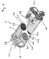
- Fig. 1 shows a heat exchanger system (1), in particular a cooler system for internal combustion engines, consisting of a heat exchanger body (2), which can be cast, for example.
- the heat exchanger body (2) has three heat exchanger chambers (3.1, 3.2, 3.3). In the heat exchanger chamber (3.1) Charge air from the engine (7.1), in the heat exchanger chamber (3.2) Fuel (7.2) and engine cooling water in the heat exchanger chamber (3.3) (7.3) cooled.
- the media to be cooled charge air, fuel and engine cooling water are stored in the respective heat exchanger chambers (3.1, 3.2, 3.3) by a cooling medium, for example in the form of Sea water that runs through the pipes (4.1, 4.2, 4.3) is cooled.
- the media to be cooled are replaced by an input (5.1, 5.2, 5.3) and an output connection (6.1, 6.2, 6.3) into the heat exchanger chambers (3.1, 3.2, 3.3) brought in.
- a heat exchanger cover (11, 12) closes in each case the end of the heat exchanger body (2).
- Fig. 2 shows a side view of the heat exchanger (2) in the charge air inlet (5.1), the fuel inlet (5.2), the engine cooling water inlet (5.3) and the charge air outlet (6.1), the fuel outlet (6.2) and the engine cooling water outlet (6.3) can be seen.
- the direction of flow is also of the cooling medium (sea water) into the cooling medium inlet (14) and from the coolant outlet (28).
- Fig. 3 shows a view from the right of that shown in Fig. 2 Heat exchanger (2) with a plan view of the heat exchanger cover (12), which the heat exchanger chambers (3.1, 3.2, 3.3) covers, the cooling medium outlet (28) on the Cover (24) is arranged.
- FIG. 4 shows a view from the left of that shown in FIG. 2 Heat exchanger (2) with a plan view of the heat exchanger cover (11), which the heat exchanger chambers (3.1, 3.2, 3.3) covers, the cooling medium inlet (14) on the Cover (13) is arranged.
- Fig. 5 shows a plan view of the heat exchanger 2 with the Cooling medium inlet (14) and the cooling medium outlet (28).
- FIG. 6 shows a section through the heat exchanger (2) along the line A-A in Fig. 2.
- sea water is through the Cooling medium inlet (14) introduced into the heat exchanger chamber (3.1).
- the heat exchanger chamber (3.1) is by means of a medium separating plate (10.1) that passes through the pipes (4.1) is closed. A contact of sea water and the charge air is thus avoided.
- the charge air is through the charge air inlet (5.1) introduced and flows around the sea water transporting pipes 4.1, whereby the charge air (7.1) to to the charge air outlet (6.1) is cooled because the heat is transferred to the Sea water is released.
- the sea water flows into the cover (21) of the heat exchanger cover (12) and is arranged by the in the lid (12) Flow channel (22) passed into the cover (23).
- the lake water flows through the heat exchanger chamber (3.2) to the Cool the fuel (7.2).
- the sea water enters the cover (15) of the heat exchanger cover (11) and flows into the Cover (19) by means of the division of the cover (17) of the baffle (18) is formed.
- the sea water now flows through the heat exchanger chamber (3.3) and cools the engine cooling water (7.3).
- the cover (26) of the heat exchanger cover (12) by the division of the Cover (24) is formed by means of the deflection plate (25), the sea water is diverted in the direction of flow and flows the heat exchanger chamber (3.3) in the opposite direction.
- FIG. 7 shows a section through the heat exchanger cover (11) along the line B-B in Fig. 6.
- the sea water flows through the coolant inlet (14) in the cover (13).
- the cover (13) covers the heat exchanger chamber (3.1).
- the cover (15) covers the heat exchanger chamber (3.2), the Sea water coming from the heat exchanger chamber (3.2) through the Flow channel (16) flows into the cover (19) and on the Deflector (18) is deflected to into the heat exchanger chamber (3.3) to flow. From the heat exchanger chamber (3.3) return flow is deflected in the cover (20) and again passed through the heat exchanger chamber (3.3).
- FIG. 8 shows a section through the heat exchanger cover (12) along the line C-C in Fig. 6.
- the lake water comes from the Heat exchanger chamber (3.1) and is in the cover (21) through the flow channel (22) into the cover (23).
- the cover (23) covers the heat exchanger chamber (3.2).
- the sea water becomes after the flow through the heat exchanger chamber (3.2) coming from the heat exchanger chamber (3.3) in the Cover (26) on the baffle (25) deflected to again to flow into the heat exchanger chamber (3.3).
- the one from the heat exchanger chamber (3.3) return flow is in the Cover (27) discharged through the coolant outlet (28).
- FIG. 9 shows a flow diagram of the known heat exchanger, that consists of three successively connected heat exchanger chambers (3.1, 3.2, 3.3) is formed.
- the cooling medium enters the Heat exchanger chamber (3.1) and flows through in succession the other heat exchanger chambers (3.2, 3.3), where necessary is the heat exchanger chambers by means of pipes (26.1, 26.2).
- FIG. 10 shows a flow diagram of the heat exchanger according to the invention (1), cooling medium through the cooling medium inlet (14) through the heat exchanger chambers (3.1, 3.2, 3.3) and exits at the coolant outlet (28).
- the heat exchanger chamber (3.1) becomes charge air (7.1) in the heat exchanger chamber (3.2) becomes fuel (7.2) and in the heat exchanger chamber (3.3) engine cooling water (7.3) is cooled.
- the core of the The invention is that the heat exchanger chambers are not necessary (3.1, 3.2, 3.3) by means of pipes, since this through the heat exchanger cover designed according to the invention takes place, the necessary flow channels and baffles exhibit. It is also possible to have two or more as three heat exchanger chambers in one heat exchanger body (2) be integrated and by appropriately adapted heat exchanger cover (11, 12) are covered.
- the heat exchanger 1 In contrast to the heat exchanger known from FIG. 9, it is possible with the heat exchanger 1 according to the invention that the The heat exchanger chamber (3.3) is flowed through several times Use of baffles in the heat exchanger covers. It is of course also possible, all or certain heat exchanger chambers flow through several times by the heat exchanger cover also in the area of the openings of the heat exchanger chambers (3.2, 3.3) are provided with baffles.
Landscapes
- Engineering & Computer Science (AREA)
- Physics & Mathematics (AREA)
- Thermal Sciences (AREA)
- Mechanical Engineering (AREA)
- General Engineering & Computer Science (AREA)
- Geometry (AREA)
- Heat-Exchange Devices With Radiators And Conduit Assemblies (AREA)
Abstract
Description
- Fig. 1
- eine perspektivische Ansicht des Wärmetauschers,
- Fig. 2
- eine seitliche Ansicht des Wärmetauschers,
- Fig. 3
- eine Ansicht von rechts des in Fig. 2. dargestellten Wärmetauschers,
- Fig. 4
- eine Ansicht von links des in Fig. 2. dargestellten Wärmetauschers,
- Fig. 5
- eine Draufsicht des Wärmetauschers,
- Fig. 6
- einen Schnitt durch den Wärmetauscher entlang der Linie A-A in Fig. 2,
- Fig. 7
- einen Schnitt durch den Wärmetauscherdeckel entlang der Linie B-B in Fig. 6,
- Fig. 8
- einen Schnitt durch den Wärmetauscherdeckel entlang der Linie C-C in Fig. 6.
- Fig. 9
- ein Flußdiagramm des bekannten Wärmetauschers
- Fig. 10
- ein Flußdiagramm des erfindungsgemäßen Wärmetauschers
Claims (9)
- Wärmetauschersystem (1), insbesondere Kühlersystem für Verbrennungsmotoren, bestehend aus einem Wärmetauscherkörper (2), der wenigstens drei Wärmetauscherkammern (3.1, 3.2, 3.3) aufweist, die jeweils von Kühlmedium transportierenden Rohren (4.1, 4.2, 4.3) in Längsrichtung durchsetzt sind und die jeweils einen Eingang- (5.1, 5.2, 5.3) und einen Ausgangsanschluß (6.1, 6.2, 6.3) für das zu kühlende Medium (7.1, 7.2, 7.3) aufweisen, wobei die an den Enden der Wärmetauscherkammern (3.1, 3.2, 3.3) angeordneten Öffnungen (8.1, 8.2, 8.3, 9.1, 9.2, 9.3) mit jeweils einer Mediumtrennplatte (10.1, 10.2, 10.3) verschlossen sind, wobei die Mediumtrennplatte (10.1, 10.2, 10.3) von den das Kühlmedium transportierenden Rohren (4.1, 4.2, 4.3) durchsetzt ist und die Mediumtrennplatte (10.1, 10.2, 10.3) mit einem Wärmetauscherdeckel (11, 12) abgedeckt ist.
- Wärmetauschersystem (1) nach Anspruch 1, dadurch gekennzeichnet, daß das Wärmetauschersystem (1) zur Kühlung von Wasserfahrzeugverbrennungsmotoren und stationären Antrieben, wie z. B. Notstromaggregaten und Pumpenantrieben eingesetzt wird.
- Wärmetauschersystem (1) nach einem der Ansprüche 1 bis 2, dadurch gekennzeichnet, daß in der Wärmetauscherkammer (3.1) Ladeluft des Motors (7.1), in der Wärmetauscherkammer (3.2) Kraftstoff (7.2) und in der Wärmetauscherkammer (3.3) Motorkühlwasser (7.3) gekühlt wird.
- Wärmetauschersystem (1) nach einem der Ansprüche 1 bis 3, dadurch gekennzeichnet, daß der Wärmetauscherkörper 2 mit den drei Wärmetauscherkammern (3.1, 3.2, 3.3) einstückig ausgebildet ist.
- Wärmetauschersystem (1) nach einem der Ansprüche 1 bis 4, dadurch gekennzeichnet, daß der Wärmetauscherkörper 2 mit den drei Wärmetauscherkammern (3.1, 3.2, 3.3) aus drei miteinander verbundenen Wärmetauscherkammern (3.1, 3.2, 3.3) gebildet ist.
- Wärmetauschersystem (1) nach einem der Ansprüche 1 bis 5, dadurch gekennzeichnet, daß der Wärmetauscherdeckel (11) eine Abdeckung (13) aufweist, die der Wärmetauscherkammer (3.1) zugeordnet ist, wobei die Abdeckung (13) einen Kühlmediumeingang (14) aufweist, eine Abdeckung (15), die der Wärmetauscherkammer (3.2) zugeordnet ist, ist mittels eines Strömungskananls (16) mit einer Abdeckung (17) verbunden, die der Wärmetauscherkammer (3.3) zugeordnet ist, wobei die Abdeckung (17) mittels eines Umlenkblechs (18) in die Teilabdeckungen (19, 20) unterteilt ist.
- Wärmetauschersystem (1) nach einem der Ansprüche 1 bis 6, dadurch gekennzeichnet, daß der Wärmetauscherdeckel (12) eine Abdeckung (21) aufweist, die der Wärmetauscherkammer (3.1) zugeordnet ist, wobei die Abdeckung (21) mittels eines Strömungskananls (22) mit einer Abdeckung (23) verbunden, die der Wärmetauscherkammer (3.2) zugeordnet ist und eine Abdeckung (24) vorgesehen ist, die mittels eines Umlenkblechs (25) in die Teilabdeckungen (26, 27) unterteilt ist, wobei die Teilabdeckung (27 ) einen Kühlmediumausgang (28) aufweist.
- Wärmetauschersystem (1) nach einem der Ansprüche 1 bis 7, dadurch gekennzeichnet, daß die Wärmetauscherdeckel (11, 12) einstückig ausgebildet sind.
- Wärmetauschersystem (1) nach einem der Ansprüche 1 bis 8, dadurch gekennzeichnet, daß die Wärmetauscherkammern (3.1, 3.2, 3.3) eine identische oder unterschiedliche Größe aufweisen.
Applications Claiming Priority (2)
| Application Number | Priority Date | Filing Date | Title |
|---|---|---|---|
| DE10102483 | 2001-01-19 | ||
| DE10102483A DE10102483A1 (de) | 2001-01-19 | 2001-01-19 | Wärmetauscher, insbesondere Kühlersystem für Verbrennungsmotoren |
Publications (3)
| Publication Number | Publication Date |
|---|---|
| EP1241425A2 true EP1241425A2 (de) | 2002-09-18 |
| EP1241425A3 EP1241425A3 (de) | 2003-08-13 |
| EP1241425B1 EP1241425B1 (de) | 2007-09-26 |
Family
ID=7671189
Family Applications (1)
| Application Number | Title | Priority Date | Filing Date |
|---|---|---|---|
| EP02001309A Expired - Lifetime EP1241425B1 (de) | 2001-01-19 | 2002-01-18 | Wärmetauscher, insbesondere Kühlersystem für Verbrennungsmotoren |
Country Status (3)
| Country | Link |
|---|---|
| EP (1) | EP1241425B1 (de) |
| AT (1) | ATE374349T1 (de) |
| DE (2) | DE10102483A1 (de) |
Cited By (1)
| Publication number | Priority date | Publication date | Assignee | Title |
|---|---|---|---|---|
| WO2005100759A1 (de) * | 2004-04-17 | 2005-10-27 | Deere & Company | Kühlsystem einer brennmaschine und brennkraftmaschine |
Families Citing this family (3)
| Publication number | Priority date | Publication date | Assignee | Title |
|---|---|---|---|---|
| JP3991786B2 (ja) | 2002-06-28 | 2007-10-17 | 株式会社デンソー | 排気熱交換装置 |
| FR2846735B1 (fr) * | 2002-10-30 | 2006-01-06 | Valeo Thermique Moteur Sa | Echangeur de chaleur a plusieurs fluides, notamment pour un vehicule automobile, et systeme de gestion de l'energie thermique associe. |
| DE102014203915A1 (de) * | 2014-03-04 | 2015-09-10 | Volkswagen Aktiengesellschaft | Ladeluftkühler für eine Brennkraftmaschine |
Family Cites Families (8)
| Publication number | Priority date | Publication date | Assignee | Title |
|---|---|---|---|---|
| GB248712A (en) * | 1925-03-03 | 1926-11-11 | Griscom Russell Co | Improvements in or relating to heat exchangers |
| GB793893A (en) * | 1956-04-05 | 1958-04-23 | Coventry Radiator & Presswork | Heat exchanger |
| GB1434754A (en) * | 1973-04-02 | 1976-05-05 | Agresto Ag | Heat exchangers |
| JPS57157010A (en) * | 1981-03-20 | 1982-09-28 | Yamaha Motor Co Ltd | Heat exchanger for cooling water of engine |
| DE3225299A1 (de) * | 1982-07-07 | 1984-01-12 | Drago Dipl.-Ing. 5020 Frechen Kober | Waermetauscher, insbesondere fuer das cargomedium eines fluessiggastankers |
| DE3323987A1 (de) * | 1983-07-02 | 1985-01-10 | Balcke-Dürr AG, 4030 Ratingen | Mehrstufiger waermetauscher |
| WO1991014084A1 (fr) * | 1990-03-14 | 1991-09-19 | Kabushiki Kaisha Komatsu Seisakusho | Dispositif de refroidissement d'un moteur diesel marine a l'eau de mer |
| JPH0436598A (ja) * | 1990-05-31 | 1992-02-06 | Mitsubishi Electric Corp | 熱交換器 |
-
2001
- 2001-01-19 DE DE10102483A patent/DE10102483A1/de not_active Ceased
-
2002
- 2002-01-18 AT AT02001309T patent/ATE374349T1/de not_active IP Right Cessation
- 2002-01-18 EP EP02001309A patent/EP1241425B1/de not_active Expired - Lifetime
- 2002-01-18 DE DE50210948T patent/DE50210948D1/de not_active Expired - Lifetime
Cited By (1)
| Publication number | Priority date | Publication date | Assignee | Title |
|---|---|---|---|---|
| WO2005100759A1 (de) * | 2004-04-17 | 2005-10-27 | Deere & Company | Kühlsystem einer brennmaschine und brennkraftmaschine |
Also Published As
| Publication number | Publication date |
|---|---|
| ATE374349T1 (de) | 2007-10-15 |
| EP1241425A3 (de) | 2003-08-13 |
| DE10102483A1 (de) | 2002-08-01 |
| DE50210948D1 (de) | 2007-11-08 |
| EP1241425B1 (de) | 2007-09-26 |
Similar Documents
| Publication | Publication Date | Title |
|---|---|---|
| AT411546B (de) | Flüssigkeitsgekühlte brennkraftmaschine mit abgasrückführeinrichtung und einer vorrichtung zur kühlung rückgeführten abgases | |
| DE2153278A1 (de) | Wärmetauscher | |
| DE102007011953A1 (de) | Wärmetauscher für ein Kraftfahrzeug | |
| DE102018106936A1 (de) | Ladeluftkühler aus einem flüssigkeitsgekühlten Vorkühler und einem luftgekühlten Hauptkühler | |
| DE10344834B4 (de) | Motorkühlsystem | |
| DE10351845B4 (de) | Abgaswärmetauscher | |
| DE3508240A1 (de) | Waermetauscher, insbesondere ladeluftkuehler mit optimierten stroemungswiderstaenden fuer alle waermeaustauschenden medien | |
| EP1241425A2 (de) | Wärmetauscher, insbesondere Kühlersystem für Verbrennungsmotoren | |
| DE20318321U1 (de) | Abgaswärmetauscher | |
| DE3148941A1 (de) | Oelkuehler in scheibenbauweise | |
| DE10021526C2 (de) | Anordnung zur Kühlung einer mehrzylindrigen Brennkraftmaschine | |
| DE102009008237A1 (de) | Brennkraftmaschine mit getrennten Kühlmittelräumen im Zylinderkopf | |
| EP2324227B1 (de) | Abgaskühlung für ein kraftfahrzeug | |
| DE102004045661B4 (de) | Vorrichtung zur Kühlung der Ladeluft bei einer aufgeladenen Brennkraftmaschine | |
| DE102006006121B4 (de) | Verbrennungskraftmaschine mit in mindestens zwei parallelen Zylinderbänken angeordneten Zylindern | |
| EP1062411B1 (de) | Wassergekühlte abgasleitung | |
| DE3701083C1 (en) | Engine housing of an internal combustion engine with banks of cylinders arranged in a V shape | |
| DE202019101397U1 (de) | Abgaskühler | |
| DE202018101360U1 (de) | Wärmeaustauscher | |
| DE102015206893B4 (de) | Abgasrückführungsmodul mit gekühltem Abgasrückführungsventil | |
| DE2909047C2 (de) | Ölkühlvorrichtung für Fahrzeuge, insbesondere für deren Schmier-, Arbeits- oder sonstiges Drucköl | |
| DE10259572B4 (de) | Wärmetauscheranordnung | |
| DE1526448A1 (de) | Brennkraftmaschine mit Abgasturbolader | |
| DE102015200952A1 (de) | Stapelscheiben-Wärmeübertrager | |
| DE102015006100A1 (de) | Vorrichtung und Verfahren zur Abgasrückführung |
Legal Events
| Date | Code | Title | Description |
|---|---|---|---|
| PUAI | Public reference made under article 153(3) epc to a published international application that has entered the european phase |
Free format text: ORIGINAL CODE: 0009012 |
|
| AK | Designated contracting states |
Kind code of ref document: A2 Designated state(s): AT BE CH CY DE DK ES FI FR GB GR IE IT LI LU MC NL PT SE TR |
|
| AX | Request for extension of the european patent |
Free format text: AL;LT;LV;MK;RO;SI |
|
| PUAL | Search report despatched |
Free format text: ORIGINAL CODE: 0009013 |
|
| AK | Designated contracting states |
Designated state(s): AT BE CH CY DE DK ES FI FR GB GR IE IT LI LU MC NL PT SE TR |
|
| AX | Request for extension of the european patent |
Extension state: AL LT LV MK RO SI |
|
| 17P | Request for examination filed |
Effective date: 20040207 |
|
| AKX | Designation fees paid |
Designated state(s): AT BE CH CY DE DK ES FI FR GB GR IE IT LI LU MC NL PT SE TR |
|
| 17Q | First examination report despatched |
Effective date: 20060103 |
|
| GRAP | Despatch of communication of intention to grant a patent |
Free format text: ORIGINAL CODE: EPIDOSNIGR1 |
|
| GRAS | Grant fee paid |
Free format text: ORIGINAL CODE: EPIDOSNIGR3 |
|
| GRAA | (expected) grant |
Free format text: ORIGINAL CODE: 0009210 |
|
| AK | Designated contracting states |
Kind code of ref document: B1 Designated state(s): AT BE CH CY DE DK ES FI FR GB GR IE IT LI LU MC NL PT SE TR |
|
| REG | Reference to a national code |
Ref country code: GB Ref legal event code: FG4D Free format text: NOT ENGLISH |
|
| REG | Reference to a national code |
Ref country code: CH Ref legal event code: EP |
|
| REF | Corresponds to: |
Ref document number: 50210948 Country of ref document: DE Date of ref document: 20071108 Kind code of ref document: P |
|
| REG | Reference to a national code |
Ref country code: IE Ref legal event code: FG4D Free format text: LANGUAGE OF EP DOCUMENT: GERMAN |
|
| ET | Fr: translation filed | ||
| PG25 | Lapsed in a contracting state [announced via postgrant information from national office to epo] |
Ref country code: FI Free format text: LAPSE BECAUSE OF FAILURE TO SUBMIT A TRANSLATION OF THE DESCRIPTION OR TO PAY THE FEE WITHIN THE PRESCRIBED TIME-LIMIT Effective date: 20070926 |
|
| GBV | Gb: ep patent (uk) treated as always having been void in accordance with gb section 77(7)/1977 [no translation filed] | ||
| PG25 | Lapsed in a contracting state [announced via postgrant information from national office to epo] |
Ref country code: GR Free format text: LAPSE BECAUSE OF FAILURE TO SUBMIT A TRANSLATION OF THE DESCRIPTION OR TO PAY THE FEE WITHIN THE PRESCRIBED TIME-LIMIT Effective date: 20071227 Ref country code: ES Free format text: LAPSE BECAUSE OF FAILURE TO SUBMIT A TRANSLATION OF THE DESCRIPTION OR TO PAY THE FEE WITHIN THE PRESCRIBED TIME-LIMIT Effective date: 20080106 |
|
| REG | Reference to a national code |
Ref country code: IE Ref legal event code: FD4D |
|
| PG25 | Lapsed in a contracting state [announced via postgrant information from national office to epo] |
Ref country code: PT Free format text: LAPSE BECAUSE OF FAILURE TO SUBMIT A TRANSLATION OF THE DESCRIPTION OR TO PAY THE FEE WITHIN THE PRESCRIBED TIME-LIMIT Effective date: 20080226 |
|
| PG25 | Lapsed in a contracting state [announced via postgrant information from national office to epo] |
Ref country code: SE Free format text: LAPSE BECAUSE OF FAILURE TO SUBMIT A TRANSLATION OF THE DESCRIPTION OR TO PAY THE FEE WITHIN THE PRESCRIBED TIME-LIMIT Effective date: 20071226 |
|
| BERE | Be: lapsed |
Owner name: EIFELWERK HEINRICH STEIN G.M.B.H. &CO.KG Effective date: 20080131 |
|
| PG25 | Lapsed in a contracting state [announced via postgrant information from national office to epo] |
Ref country code: DK Free format text: LAPSE BECAUSE OF FAILURE TO SUBMIT A TRANSLATION OF THE DESCRIPTION OR TO PAY THE FEE WITHIN THE PRESCRIBED TIME-LIMIT Effective date: 20070926 |
|
| PLBE | No opposition filed within time limit |
Free format text: ORIGINAL CODE: 0009261 |
|
| STAA | Information on the status of an ep patent application or granted ep patent |
Free format text: STATUS: NO OPPOSITION FILED WITHIN TIME LIMIT |
|
| PG25 | Lapsed in a contracting state [announced via postgrant information from national office to epo] |
Ref country code: MC Free format text: LAPSE BECAUSE OF NON-PAYMENT OF DUE FEES Effective date: 20080131 |
|
| REG | Reference to a national code |
Ref country code: CH Ref legal event code: PL |
|
| 26N | No opposition filed |
Effective date: 20080627 |
|
| PG25 | Lapsed in a contracting state [announced via postgrant information from national office to epo] |
Ref country code: IE Free format text: LAPSE BECAUSE OF FAILURE TO SUBMIT A TRANSLATION OF THE DESCRIPTION OR TO PAY THE FEE WITHIN THE PRESCRIBED TIME-LIMIT Effective date: 20070926 Ref country code: LI Free format text: LAPSE BECAUSE OF NON-PAYMENT OF DUE FEES Effective date: 20080131 Ref country code: CH Free format text: LAPSE BECAUSE OF NON-PAYMENT OF DUE FEES Effective date: 20080131 |
|
| PG25 | Lapsed in a contracting state [announced via postgrant information from national office to epo] |
Ref country code: GB Free format text: LAPSE BECAUSE OF FAILURE TO SUBMIT A TRANSLATION OF THE DESCRIPTION OR TO PAY THE FEE WITHIN THE PRESCRIBED TIME-LIMIT Effective date: 20070926 |
|
| PG25 | Lapsed in a contracting state [announced via postgrant information from national office to epo] |
Ref country code: BE Free format text: LAPSE BECAUSE OF NON-PAYMENT OF DUE FEES Effective date: 20080131 |
|
| PG25 | Lapsed in a contracting state [announced via postgrant information from national office to epo] |
Ref country code: AT Free format text: LAPSE BECAUSE OF NON-PAYMENT OF DUE FEES Effective date: 20080118 |
|
| PG25 | Lapsed in a contracting state [announced via postgrant information from national office to epo] |
Ref country code: CY Free format text: LAPSE BECAUSE OF FAILURE TO SUBMIT A TRANSLATION OF THE DESCRIPTION OR TO PAY THE FEE WITHIN THE PRESCRIBED TIME-LIMIT Effective date: 20070926 |
|
| PGFP | Annual fee paid to national office [announced via postgrant information from national office to epo] |
Ref country code: FR Payment date: 20100209 Year of fee payment: 9 Ref country code: IT Payment date: 20100123 Year of fee payment: 9 |
|
| PG25 | Lapsed in a contracting state [announced via postgrant information from national office to epo] |
Ref country code: LU Free format text: LAPSE BECAUSE OF NON-PAYMENT OF DUE FEES Effective date: 20080118 |
|
| PG25 | Lapsed in a contracting state [announced via postgrant information from national office to epo] |
Ref country code: TR Free format text: LAPSE BECAUSE OF FAILURE TO SUBMIT A TRANSLATION OF THE DESCRIPTION OR TO PAY THE FEE WITHIN THE PRESCRIBED TIME-LIMIT Effective date: 20070926 |
|
| PGFP | Annual fee paid to national office [announced via postgrant information from national office to epo] |
Ref country code: NL Payment date: 20100121 Year of fee payment: 9 |
|
| REG | Reference to a national code |
Ref country code: NL Ref legal event code: V1 Effective date: 20110801 |
|
| REG | Reference to a national code |
Ref country code: FR Ref legal event code: ST Effective date: 20110930 |
|
| PG25 | Lapsed in a contracting state [announced via postgrant information from national office to epo] |
Ref country code: FR Free format text: LAPSE BECAUSE OF NON-PAYMENT OF DUE FEES Effective date: 20110131 |
|
| PG25 | Lapsed in a contracting state [announced via postgrant information from national office to epo] |
Ref country code: IT Free format text: LAPSE BECAUSE OF NON-PAYMENT OF DUE FEES Effective date: 20110118 Ref country code: NL Free format text: LAPSE BECAUSE OF NON-PAYMENT OF DUE FEES Effective date: 20110801 |
|
| PGFP | Annual fee paid to national office [announced via postgrant information from national office to epo] |
Ref country code: DE Payment date: 20120326 Year of fee payment: 11 |
|
| PG25 | Lapsed in a contracting state [announced via postgrant information from national office to epo] |
Ref country code: DE Free format text: LAPSE BECAUSE OF NON-PAYMENT OF DUE FEES Effective date: 20130801 |
|
| REG | Reference to a national code |
Ref country code: DE Ref legal event code: R119 Ref document number: 50210948 Country of ref document: DE Effective date: 20130801 |