EP1241377A2 - Verfahren zur Abstimmung eines Maschinenlagers - Google Patents
Verfahren zur Abstimmung eines Maschinenlagers Download PDFInfo
- Publication number
- EP1241377A2 EP1241377A2 EP02002597A EP02002597A EP1241377A2 EP 1241377 A2 EP1241377 A2 EP 1241377A2 EP 02002597 A EP02002597 A EP 02002597A EP 02002597 A EP02002597 A EP 02002597A EP 1241377 A2 EP1241377 A2 EP 1241377A2
- Authority
- EP
- European Patent Office
- Prior art keywords
- machine
- additional module
- bearing
- spring
- additional
- Prior art date
- Legal status (The legal status is an assumption and is not a legal conclusion. Google has not performed a legal analysis and makes no representation as to the accuracy of the status listed.)
- Granted
Links
Images

Classifications
-
- F—MECHANICAL ENGINEERING; LIGHTING; HEATING; WEAPONS; BLASTING
- F16—ENGINEERING ELEMENTS AND UNITS; GENERAL MEASURES FOR PRODUCING AND MAINTAINING EFFECTIVE FUNCTIONING OF MACHINES OR INSTALLATIONS; THERMAL INSULATION IN GENERAL
- F16F—SPRINGS; SHOCK-ABSORBERS; MEANS FOR DAMPING VIBRATION
- F16F15/00—Suppression of vibrations in systems; Means or arrangements for avoiding or reducing out-of-balance forces, e.g. due to motion
- F16F15/02—Suppression of vibrations of non-rotating, e.g. reciprocating systems; Suppression of vibrations of rotating systems by use of members not moving with the rotating systems
- F16F15/04—Suppression of vibrations of non-rotating, e.g. reciprocating systems; Suppression of vibrations of rotating systems by use of members not moving with the rotating systems using elastic means
- F16F15/046—Suppression of vibrations of non-rotating, e.g. reciprocating systems; Suppression of vibrations of rotating systems by use of members not moving with the rotating systems using elastic means using combinations of springs of different kinds
Definitions
- the invention relates to a method according to the generic term of Claim 1.
- the object of the invention is to largely avoid this effort, and to enable the possibility of a modification in operation.
- the object of the invention is to largely avoid this effort, and to enable the possibility of a modification in operation.
- the additional properties of the add-on module can not only be in one direction, for example, the vertical, but also in the two directions orthogonal to it.
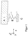
- FIG. 1 shows a machine 1 which is supported on a machine foundation 3 via a machine bearing.
- the machine bearing - here in the function of a base bearing 2 is formed from a spring 4, the rigidity of which is C 1Z .
- the coordinate system is defined by the orthogonal coordinates x, y, z.
- the Z coordinate is the vertical direction in which the weight of the machine 1 works.
- the stiffness C 1Z of the spring 4 is adapted to the weight and is made relatively soft.
- the spring 4 of the base bearing 2 is at least according to the invention an additional module 5 in the form of a second spring 6 connected in parallel.
- This second spring 6 is relieved of any weight of machine 1 during installation, d. That is, that the second spring 6 only after the spring 4 has deflected into the between Machine 1 and machine foundation 3 remaining space installed becomes.
- the stiffness C 2Z of the second spring 6 can be designed without regard to the load due to weight forces solely on the basis of the desired natural frequency of the vibration system formed from the mass m of the machine 1 and the stiffnesses C 1Z + C 2Z .
- the natural frequency can be varied by choosing the stiffness C 2Z in such a way that dangerous resonances are avoided.
- the additional module 5 can also be formed from a plurality of springs, for example a third spring 7 with a stiffness C 3Z , which is connected in parallel with the base bearing 2.
- the Affect stiffness in the x and y directions By using the additional module 5 according to the invention, the Affect stiffness in the x and y directions.
- the indices x, y, z indicate the direction of the stiffness.
- the method according to the invention enables the installation to be carried out with minimal effort the adaptation of the machine bearings of an already installed machine without the machine must be removed again. This is particularly beneficial in Internal combustion engines that serve a boat drive. Because the installation space there is very cramped are present, the method according to the invention is easy to assemble, especially since no new adjustment of the system has to be made.
Landscapes
- Engineering & Computer Science (AREA)
- General Engineering & Computer Science (AREA)
- Physics & Mathematics (AREA)
- Acoustics & Sound (AREA)
- Aviation & Aerospace Engineering (AREA)
- Mechanical Engineering (AREA)
- Vibration Prevention Devices (AREA)
- Support Of The Bearing (AREA)
Abstract
Description
- Fig. 1
- ein Maschinenlager mit einem Grundlager
- Fig. 2
- ein Maschinenlager mit Grundlager und dazu parallel geschaltetem Zusatzmodul
- C1
- Steifigkeit der Feder 4 (Grundlager 2 )
- C2
- Steifigkeit der Feder 6
- C3
- Steifigkeit der Feder 7
Claims (2)
- Verfahren zur Abstimmung eines Maschinenlagers, bei dem die Gewichtskraft der Maschine ausschließlich von einem Grundlager aufgenommen wird, dadurch gekennzeichnet, daß zur differenzierten Abstimmung des Maschinenlagers auf Zusatzkräfte, wie z.B. oszillierende Massenkräfte, dem Grundlager (2) mindestens ein von der Gewichtskraft entlastetes Zusatzmodul (5) parallel geschaltet ist, derart, daß durch die Federsteifigkeit des Zusatzmoduls (5) das aus Grundlager (2) und Zusatzmodul (5) kombinierte Federsystem vorgegebenen Eigenschaften bezüglich Dämpfung und Eigenfrequenz entspricht.
- Verfahren nach Anspruch 1, dadurch gekennzeichnet, daß durch die Federsteifigkeit des Zusatzmoduls (5) richtungsabhängige Eigenschaften bezüglich Dämpfung und Eigenfrequenz darstellbar sind.
Applications Claiming Priority (2)
| Application Number | Priority Date | Filing Date | Title |
|---|---|---|---|
| DE10112477A DE10112477A1 (de) | 2001-03-15 | 2001-03-15 | Verfahren zur Abstimmung eines Maschinenlagers |
| DE10112477 | 2001-03-15 |
Publications (3)
| Publication Number | Publication Date |
|---|---|
| EP1241377A2 true EP1241377A2 (de) | 2002-09-18 |
| EP1241377A3 EP1241377A3 (de) | 2003-05-07 |
| EP1241377B1 EP1241377B1 (de) | 2004-11-17 |
Family
ID=7677573
Family Applications (1)
| Application Number | Title | Priority Date | Filing Date |
|---|---|---|---|
| EP02002597A Expired - Lifetime EP1241377B1 (de) | 2001-03-15 | 2002-02-05 | Verfahren zur Abstimmung eines Maschinenlagers |
Country Status (4)
| Country | Link |
|---|---|
| US (1) | US6688587B2 (de) |
| EP (1) | EP1241377B1 (de) |
| DE (2) | DE10112477A1 (de) |
| ES (1) | ES2227332T3 (de) |
Cited By (1)
| Publication number | Priority date | Publication date | Assignee | Title |
|---|---|---|---|---|
| AT506028A3 (de) * | 2007-11-12 | 2011-11-15 | Metso Paper Inc | Verfahren und vorrichtung zur minderung von schwingungsstörungen in einer streichstation |
Families Citing this family (5)
| Publication number | Priority date | Publication date | Assignee | Title |
|---|---|---|---|---|
| FR2851742B1 (fr) * | 2003-02-28 | 2005-05-06 | Arslanian Pierre Jean Der | Suspension stabilisatrice pour l'asservissement d'attitude de vehicule roulants |
| NL1027304C2 (nl) * | 2004-10-20 | 2006-04-24 | Mecal Applied Mechanics B V | Ondersteuningsconstructie, fixatieorgaan en werkwijze. |
| CN106090094A (zh) * | 2016-08-26 | 2016-11-09 | 中国工程物理研究院总体工程研究所 | 一种刚度可调的弹簧组件 |
| CN110725892B (zh) * | 2019-11-23 | 2021-01-12 | 李道飞 | 一种带冷却液的减震装置 |
| CN120354509B (zh) * | 2025-06-23 | 2025-09-02 | 同济大学 | 一种适配样品的弹簧组刚度智能调控优化方法及相关装置 |
Family Cites Families (15)
| Publication number | Priority date | Publication date | Assignee | Title |
|---|---|---|---|---|
| DE692713C (de) * | 1937-03-27 | 1940-06-25 | Getefo Ges Fuer Tech Fortschri | Elastische Lagerung |
| US2770434A (en) * | 1949-04-29 | 1956-11-13 | James A Mcnally | Pneumatic mounting system |
| FR61342E (fr) * | 1951-05-11 | 1955-04-25 | Sncf | Ressort à lame sans frottement et à flexibilité variable |
| US3794277A (en) * | 1972-08-14 | 1974-02-26 | A Smedley | Earthquake resistant support |
| DE8002600U1 (de) * | 1980-02-01 | 1980-06-26 | Broneske, Erwin, 2085 Quickborn | Lagerelement |
| DE3637294A1 (de) * | 1986-11-03 | 1988-05-11 | Wolf Woco & Co Franz J | Tragfedersystem |
| DE3800587C1 (de) * | 1988-01-12 | 1989-04-27 | Krupp Brueninghaus Gmbh, 5980 Werdohl, De | |
| DE4002201A1 (de) * | 1990-01-23 | 1991-07-25 | Siemens Ag | Elektrische maschine mit einem rotor |
| DE4101864A1 (de) * | 1991-01-23 | 1992-07-30 | Gerlach Rainer | Gewichtsausgleichsanordnung zur schwingungsisolation selbst- oder fremderregter massen |
| DE4314975C1 (de) * | 1993-05-06 | 1995-03-16 | Grammer Ag | Abgefedertes Sitzgestell, insbes. für einen Fahrzeugsitz |
| US5564537A (en) * | 1994-04-04 | 1996-10-15 | Cooper Tire & Rubber Company | Adaptive-passive vibration control system |
| US5505282A (en) * | 1994-09-06 | 1996-04-09 | The University Of Connecticut | Single mass dual frequency fixed delayed resonator |
| DE19608617A1 (de) * | 1996-03-06 | 1997-09-11 | Linke Hofmann Busch | Verfahren zur Verbesserung des Fahrkomforts |
| US6193032B1 (en) * | 1998-03-02 | 2001-02-27 | The Penn State Research Foundation | Piezoceramic vibration control device and tuning control thereof |
| US6059274A (en) * | 1998-05-04 | 2000-05-09 | Gte Internetworking Incorporated | Vibration reduction system using impedance regulated active mounts and method for reducing vibration |
-
2001
- 2001-03-15 DE DE10112477A patent/DE10112477A1/de not_active Withdrawn
-
2002
- 2002-02-05 EP EP02002597A patent/EP1241377B1/de not_active Expired - Lifetime
- 2002-02-05 ES ES02002597T patent/ES2227332T3/es not_active Expired - Lifetime
- 2002-02-05 DE DE50201538T patent/DE50201538D1/de not_active Expired - Lifetime
- 2002-03-13 US US10/096,697 patent/US6688587B2/en not_active Expired - Lifetime
Non-Patent Citations (1)
| Title |
|---|
| None |
Cited By (1)
| Publication number | Priority date | Publication date | Assignee | Title |
|---|---|---|---|---|
| AT506028A3 (de) * | 2007-11-12 | 2011-11-15 | Metso Paper Inc | Verfahren und vorrichtung zur minderung von schwingungsstörungen in einer streichstation |
Also Published As
| Publication number | Publication date |
|---|---|
| EP1241377A3 (de) | 2003-05-07 |
| DE50201538D1 (de) | 2004-12-23 |
| US20020171024A1 (en) | 2002-11-21 |
| US6688587B2 (en) | 2004-02-10 |
| DE10112477A1 (de) | 2002-09-19 |
| EP1241377B1 (de) | 2004-11-17 |
| ES2227332T3 (es) | 2005-04-01 |
Similar Documents
| Publication | Publication Date | Title |
|---|---|---|
| DE4019304C1 (de) | ||
| DE102013203560B4 (de) | Brennkraftmaschine mit auf der Kurbelwelle angeordnetem und als Unwucht dienendem Ausgleichsgewicht und Verfahren zur Herstellung der Kurbelwelle | |
| EP2833018B1 (de) | Fliehkraftpendel und Antriebssystem mit Fliehkraftpendel | |
| EP3243011B1 (de) | Integrierte doppelt elastische aktivteilabkopplung | |
| DE102012200028B4 (de) | Verfahren zum Ausgleich der Massenmomente einer Antriebseinheit und Antriebseinheit zur Durchführung eines derartigen Verfahrens | |
| EP1241377A2 (de) | Verfahren zur Abstimmung eines Maschinenlagers | |
| DE3138165A1 (de) | "hubkolbenbrennkratfmaschine, vorzugsweise vierzylindriger bauart" | |
| DE102013206931A1 (de) | Brennkraftmaschine umfassend eine Kurbelwelle mit als Unwucht dienendem Ausgleichsgewicht und Verfahren zur Herstellung der Kurbelwelle | |
| DE102009047545A1 (de) | Mehrzylinder-Reihen-Brennkraftmaschine für ein Kraftfahrzeug | |
| DE3431966A1 (de) | Ausgleichssystem | |
| EP0495021B1 (de) | Massenausgleich für eine hubkolbenbrennkraftmaschine | |
| EP3208441B1 (de) | Viertakt-hubkolbenmotor in v-bauweise mit 20 zylindern | |
| DE2904066A1 (de) | Faecherfoermige kolbenmaschine | |
| DE19633421B4 (de) | Schiffsantriebsanlage mit schwingungsdämpfend gelagertem Antriebsmotor | |
| EP1923600A1 (de) | Gegengewichtsanordnung für einen Verbrennungsmotor in einem Kraftfahrzeug | |
| DE102016213483A1 (de) | Vorrichtung zum Ausgleich freier Massenkräfte einer Hubkolbenbrennkraftmaschine | |
| DE19620473A1 (de) | Schwingungsdämpfer für eine Kraftstoffanlage | |
| EP1564437B1 (de) | System mit Kurbelwelle und Schwungrad und Verfahren zur Herstellung eines derartigen Systems | |
| DE10010095B4 (de) | Kurbelwelle mit hoher Schwingungsdämpfung | |
| DE10207077A1 (de) | Kurbelwellen für eine V-Motoren-Baureihe | |
| EP2772654B1 (de) | Kurbelwelle mit als Unwucht dienendem Ausgleichsgewicht und Verfahren zur Herstellung der Kurbelwelle | |
| DE102016111293B4 (de) | Einrichtung zur Kühlschmierstoffversorgung für Werkzeugmaschinen | |
| DE102017222468B3 (de) | Hubkolbenmotor sowie Kraftfahrzeug | |
| DE102019007007A1 (de) | Brennkraftmaschine mit einem Zylinderkurbelgehäuse und einem Zylinderkopf mit integriertem höhenverstellbarem Lüfteranbau für elastische Keilrippenriemen | |
| DE4319333A1 (de) | Kurbelwelle mit Massenausgleich zweiter Ordnung |
Legal Events
| Date | Code | Title | Description |
|---|---|---|---|
| PUAI | Public reference made under article 153(3) epc to a published international application that has entered the european phase |
Free format text: ORIGINAL CODE: 0009012 |
|
| AK | Designated contracting states |
Kind code of ref document: A2 Designated state(s): AT BE CH CY DE DK ES FI FR GB GR IE IT LI LU MC NL PT SE TR |
|
| AX | Request for extension of the european patent |
Free format text: AL;LT;LV;MK;RO;SI |
|
| PUAL | Search report despatched |
Free format text: ORIGINAL CODE: 0009013 |
|
| AK | Designated contracting states |
Designated state(s): AT BE CH CY DE DK ES FI FR GB GR IE IT LI LU MC NL PT SE TR |
|
| AX | Request for extension of the european patent |
Extension state: AL LT LV MK RO SI |
|
| RIC1 | Information provided on ipc code assigned before grant |
Ipc: 7F 16F 3/00 B Ipc: 7F 16F 15/00 A |
|
| 17P | Request for examination filed |
Effective date: 20030804 |
|
| 17Q | First examination report despatched |
Effective date: 20031006 |
|
| AKX | Designation fees paid |
Designated state(s): DE ES FR GB IT |
|
| GRAP | Despatch of communication of intention to grant a patent |
Free format text: ORIGINAL CODE: EPIDOSNIGR1 |
|
| GRAS | Grant fee paid |
Free format text: ORIGINAL CODE: EPIDOSNIGR3 |
|
| GRAA | (expected) grant |
Free format text: ORIGINAL CODE: 0009210 |
|
| AK | Designated contracting states |
Kind code of ref document: B1 Designated state(s): DE ES FR GB IT |
|
| REG | Reference to a national code |
Ref country code: GB Ref legal event code: FG4D Free format text: NOT ENGLISH |
|
| REG | Reference to a national code |
Ref country code: IE Ref legal event code: FG4D Free format text: GERMAN |
|
| REF | Corresponds to: |
Ref document number: 50201538 Country of ref document: DE Date of ref document: 20041223 Kind code of ref document: P |
|
| GBT | Gb: translation of ep patent filed (gb section 77(6)(a)/1977) | ||
| REG | Reference to a national code |
Ref country code: ES Ref legal event code: FG2A Ref document number: 2227332 Country of ref document: ES Kind code of ref document: T3 |
|
| REG | Reference to a national code |
Ref country code: IE Ref legal event code: FD4D |
|
| PLBE | No opposition filed within time limit |
Free format text: ORIGINAL CODE: 0009261 |
|
| STAA | Information on the status of an ep patent application or granted ep patent |
Free format text: STATUS: NO OPPOSITION FILED WITHIN TIME LIMIT |
|
| 26N | No opposition filed |
Effective date: 20050818 |
|
| ET | Fr: translation filed | ||
| REG | Reference to a national code |
Ref country code: FR Ref legal event code: CD |
|
| REG | Reference to a national code |
Ref country code: DE Ref legal event code: R081 Ref document number: 50201538 Country of ref document: DE Owner name: MAN TRUCK & BUS AG, DE Free format text: FORMER OWNER: MAN NUTZFAHRZEUGE AG, 80995 MUENCHEN, DE Effective date: 20110406 |
|
| REG | Reference to a national code |
Ref country code: ES Ref legal event code: PC2A Owner name: "MAN TRUCK & Effective date: 20110620 Ref country code: ES Ref legal event code: PC2A Owner name: MAN TRUCK & BUS AG Effective date: 20110620 |
|
| REG | Reference to a national code |
Ref country code: FR Ref legal event code: PLFP Year of fee payment: 15 |
|
| REG | Reference to a national code |
Ref country code: FR Ref legal event code: PLFP Year of fee payment: 16 |
|
| REG | Reference to a national code |
Ref country code: FR Ref legal event code: PLFP Year of fee payment: 17 |
|
| REG | Reference to a national code |
Ref country code: DE Ref legal event code: R081 Ref document number: 50201538 Country of ref document: DE Owner name: MAN TRUCK & BUS SE, DE Free format text: FORMER OWNER: MAN TRUCK & BUS AG, 80995 MUENCHEN, DE |
|
| PGFP | Annual fee paid to national office [announced via postgrant information from national office to epo] |
Ref country code: FR Payment date: 20210223 Year of fee payment: 20 Ref country code: IT Payment date: 20210223 Year of fee payment: 20 |
|
| PGFP | Annual fee paid to national office [announced via postgrant information from national office to epo] |
Ref country code: ES Payment date: 20210317 Year of fee payment: 20 Ref country code: GB Payment date: 20210223 Year of fee payment: 20 |
|
| PGFP | Annual fee paid to national office [announced via postgrant information from national office to epo] |
Ref country code: DE Payment date: 20210329 Year of fee payment: 20 |
|
| REG | Reference to a national code |
Ref country code: GB Ref legal event code: PE20 Expiry date: 20220204 |
|
| PG25 | Lapsed in a contracting state [announced via postgrant information from national office to epo] |
Ref country code: GB Free format text: LAPSE BECAUSE OF EXPIRATION OF PROTECTION Effective date: 20220204 |
|
| REG | Reference to a national code |
Ref country code: ES Ref legal event code: FD2A Effective date: 20220526 |
|
| PG25 | Lapsed in a contracting state [announced via postgrant information from national office to epo] |
Ref country code: ES Free format text: LAPSE BECAUSE OF EXPIRATION OF PROTECTION Effective date: 20220206 |