EP1241327A1 - Oil separator - Google Patents
Oil separator Download PDFInfo
- Publication number
- EP1241327A1 EP1241327A1 EP02001593A EP02001593A EP1241327A1 EP 1241327 A1 EP1241327 A1 EP 1241327A1 EP 02001593 A EP02001593 A EP 02001593A EP 02001593 A EP02001593 A EP 02001593A EP 1241327 A1 EP1241327 A1 EP 1241327A1
- Authority
- EP
- European Patent Office
- Prior art keywords
- oil
- case body
- filter
- oil separator
- gaseous fluid
- Prior art date
- Legal status (The legal status is an assumption and is not a legal conclusion. Google has not performed a legal analysis and makes no representation as to the accuracy of the status listed.)
- Withdrawn
Links
- 239000003595 mist Substances 0.000 claims abstract description 61
- 239000012530 fluid Substances 0.000 claims abstract description 57
- 230000015572 biosynthetic process Effects 0.000 claims description 30
- 238000002485 combustion reaction Methods 0.000 claims description 18
- 238000000926 separation method Methods 0.000 abstract description 24
- 239000007789 gas Substances 0.000 description 181
- 239000003921 oil Substances 0.000 description 163
- 239000003507 refrigerant Substances 0.000 description 17
- 238000010438 heat treatment Methods 0.000 description 10
- 230000003247 decreasing effect Effects 0.000 description 6
- 229920003002 synthetic resin Polymers 0.000 description 5
- 239000000057 synthetic resin Substances 0.000 description 5
- 239000002918 waste heat Substances 0.000 description 4
- 238000001816 cooling Methods 0.000 description 3
- 230000007423 decrease Effects 0.000 description 3
- 239000010687 lubricating oil Substances 0.000 description 3
- 239000004745 nonwoven fabric Substances 0.000 description 3
- 238000010276 construction Methods 0.000 description 2
- 238000007599 discharging Methods 0.000 description 2
- 230000000694 effects Effects 0.000 description 2
- 239000000446 fuel Substances 0.000 description 2
- 239000007788 liquid Substances 0.000 description 2
- 238000005192 partition Methods 0.000 description 2
- 230000001143 conditioned effect Effects 0.000 description 1
- 230000006866 deterioration Effects 0.000 description 1
- 239000002737 fuel gas Substances 0.000 description 1
- 238000004519 manufacturing process Methods 0.000 description 1
- 238000009423 ventilation Methods 0.000 description 1
Images





Classifications
-
- F—MECHANICAL ENGINEERING; LIGHTING; HEATING; WEAPONS; BLASTING
- F01—MACHINES OR ENGINES IN GENERAL; ENGINE PLANTS IN GENERAL; STEAM ENGINES
- F01M—LUBRICATING OF MACHINES OR ENGINES IN GENERAL; LUBRICATING INTERNAL COMBUSTION ENGINES; CRANKCASE VENTILATING
- F01M13/00—Crankcase ventilating or breathing
- F01M13/04—Crankcase ventilating or breathing having means for purifying air before leaving crankcase, e.g. removing oil
-
- F—MECHANICAL ENGINEERING; LIGHTING; HEATING; WEAPONS; BLASTING
- F01—MACHINES OR ENGINES IN GENERAL; ENGINE PLANTS IN GENERAL; STEAM ENGINES
- F01M—LUBRICATING OF MACHINES OR ENGINES IN GENERAL; LUBRICATING INTERNAL COMBUSTION ENGINES; CRANKCASE VENTILATING
- F01M13/00—Crankcase ventilating or breathing
- F01M13/04—Crankcase ventilating or breathing having means for purifying air before leaving crankcase, e.g. removing oil
- F01M2013/0438—Crankcase ventilating or breathing having means for purifying air before leaving crankcase, e.g. removing oil with a filter
-
- Y—GENERAL TAGGING OF NEW TECHNOLOGICAL DEVELOPMENTS; GENERAL TAGGING OF CROSS-SECTIONAL TECHNOLOGIES SPANNING OVER SEVERAL SECTIONS OF THE IPC; TECHNICAL SUBJECTS COVERED BY FORMER USPC CROSS-REFERENCE ART COLLECTIONS [XRACs] AND DIGESTS
- Y10—TECHNICAL SUBJECTS COVERED BY FORMER USPC
- Y10S—TECHNICAL SUBJECTS COVERED BY FORMER USPC CROSS-REFERENCE ART COLLECTIONS [XRACs] AND DIGESTS
- Y10S55/00—Gas separation
- Y10S55/19—Crankcase ventilation
Definitions
- the present invention relates to an oil separator for separating the oil mist from gaseous fluids, such as a blowby gas, and in particular, to an oil separator which is suitably used in a gas engine for a gas heat pump type air conditioner.
- An air conditioner in which a heat pump is used for cooling and heating operations, is provided with a refrigerant circuit comprising an indoor heat exchange apparatus, a compressor, an outdoor heat exchange apparatus, an expansion valve, etc.
- a refrigerant circuit comprising an indoor heat exchange apparatus, a compressor, an outdoor heat exchange apparatus, an expansion valve, etc.
- the refrigerant circulates in the refrigerant circuit and exchanges heat with air in the indoor heat exchange apparatus and the outdoor heat exchange apparatus, the air conditioned chamber is heated or cooled.
- a refrigerant heating apparatus for heating the refrigerant directly is sometimes provided in the refrigerant circuit.
- an air conditioner which comprises a gas engine, instead of an ordinary motor, as a driving source for the compressor provided in the refrigerant circuit.
- An air conditioner utilizing a gas engine is called a gas heat pump type air conditioner (abbreviated as "GHP" below).
- GHP gas heat pump type air conditioner
- the GHP can use gas, which is relatively cheap, as fuel; therefore, the running cost thereof can be reduced, compared with an air conditioner comprising a compressor driven by the ordinary motor (abbreviated as "EHP” below).
- the heating ability can be improved, and the use efficiency of energy can also be improved.
- the GHP does not require a special device, such as the refrigerant heating device explained above.
- the GHP can utilize the engine waste heat to defrost the outdoor heat exchange apparatus during the heating operation.
- the EHP defrosts the outdoor heat exchange apparatus by stopping the heating operation and temporarily performing the cooling operation. That is, when the EHP defrosts, cooled air is introduced into the chamber. Therefore, a person in the chamber feels unpleasant.
- the GHP can utilize the waste heat, and it can continuously perform the heating operation without such the problem which is caused by the EHP.
- the GHP has many advantages as explained above; however, it also has the following problems.
- the GHP uses the gas engine as a driving source for the compressor.
- oil contained in the blowby gas may rise to problems.
- the blowby gas is gas which leaks from the combustion chamber into a crank case through a gap between the piston ring and the cylinder.
- the blowby gas is returned from the crank case into an engine intake system and is then sent to the combustion chamber again.
- blowby gas line a line for the flow of the blowby gas
- oil separators for accumulating and removing the oil mist, such as a blowby gas filter
- FIGS. 11, 12A, and 12B show a conventional oil separator which is used as a blowby gas filter.
- reference number 140 denotes an oil separator
- 141 denotes a case body
- 142 denotes a lid
- 143 denotes a filter
- 144 denotes gaseous fluid entrance
- 145 denotes a gaseous fluid exit
- 146 denotes an outflow exit for the oil mist accumulated by the filter 143.
- the case body 141 and the lid 142 comprise the casing of the oil separator 140.
- the blowby gas which flows in through the entrance 144 connected to the crank case of the gas engine, passes through the filter 143 and is sucked through the exit 145 by the intake system of the gas engine.
- the oil mist contained in the blowby gas is separated and removed as it passes through the filter 143, falls to the bottom of the case body 141, and is then returned to the oil pan of the gas engine through the outflow exit 146.
- the height of the filter 143, through which the blowby gas passes is increased as much as possible. It is necessary to replace the filter 143 after a given operation time of the oil separator 140.
- the lid 142 can detach from the case body 141.
- the lid 142 is attached at the side of the case body 141, where an opening having the largest area can be formed.
- the lid 142 is formed at the side of the case body 141, there is the possibility that the oil falling to the bottom of the case body 141 will leak from a gap between the case body 141 and the lid 142.
- the pressure at the bottom of the case body 141 where the outflow exit 146 is provided is greater than the atmospheric pressure at the outside of the case body 141. That is, the pressure at the bottom of the case body 141 where the outflow exit 146 is provided in a positive pressure region. Therefore, there may be oil leak due to the pressure difference, at any gap occurring at the contact portion.
- the filter 143 is made of nonwoven fabrics, which have inferior shape maintaining properties, there is the problem that a gap S can easily occur between the filter 143 and the inside wall of the case body 141, as shown in FIG. 12A. If the gap S is generated, the blowby gas containing the oil mist passes through the gap S and flows out through the exit 145, without passing through the filter 143. The gap S decreases the separation efficiency of the oil mist in the oil separator 140. Therefore, it is desired for the blowby gas to pass with certainty through the filter 143. In addition, in the conventional oil separator 140, since the separation of the oil mist is carried out by only the filter 143, there is the problem that it is difficult to obtain a sufficient separation efficiency.
- the separation efficiency can be improved by increasing the thickness of the filter 143.
- an increase in the thickness of the filter 143 causes a significant pressure loss. Therefore, the separation efficiency cannot be sufficiently improved only by increasing the thickness of the filter 143.
- one of objects of the present invention is to improve the performances of the oil separator for removing the oil mist from the gaseous fluids, such as the blowby gas.
- an object of the present invention is to provide an oil separator which can be manufactured at a low cost and can prevent the leakage of removed oil, and an oil separator which has improved separation efficiency of the oil mist contained in the gaseous fluids without increasing the pressure loss.
- the present invention provides an oil separator for separating oil from a gaseous fluid containing oil in the state of a mist comprising: a hollow case body comprising an opening at the top thereof; a lid for covering the opening formed at the case body; and a filter in the case body; wherein an entrance for flowing of the gaseous fluid into the case body is formed at the lower side of the case body, an exit for outward flow of the gaseous fluid is formed at the lid, and an outflow exit for outward flow of oil which has been separated is formed at the bottom of the case body.
- the separator since the opening, which is formed at the top of the case body, is covered with the lid, the case body and the lid do not come into contact with each other at the bottom of the case body, i.e., at the portion to which the separated oil descends. Therefore, it is possible to flow out with certainty the separated and removed oil from the oil separator without oil leaks at the contact portion between the case body and the lid.
- the separator has a simple structure and it can be manufactured at a low cost.
- the oil separator it is preferable to provide a guide for introducing the gaseous fluid flowing from the entrance to the exit into the center of the filter.
- the gaseous fluid is introduced into the center of the filter by the guide, the amount of the gaseous fluid which does not pass through the filter can be significantly decreased. If there is a gap between the filter and the inside wall of the case body, it is possible to improve the separation efficiency of the oil mist.
- the guide it is preferable for the guide to be a cylindrical member provided at the bottom surface of the lid so as to protrude toward the inside of the case body, or to be a plate ring member provided at the inside wall of the case body above the entrance so as to protrude toward the inside of the case body.
- the case body in the oil separator, it is preferable for the case body to comprise a large upper portion in which the filter is placed and a small lower portion in which the entrance and the outflow exit are provided, and for the gaseous fluid flowing from the entrance to the exit to be introduced into the center of the filter at a connection portion between the large upper portion and the small lower portion.
- connection portion between the large upper portion and the small lower portion acts as a guide for introducing the gaseous fluid into the center of the filter, if there is the gap between the filter and the case body and the lid, it is possible to improve the separation efficiency of the oil mist.
- the gaseous fluid entrance and the outflow exit for the separated oil to be formed in a positive pressure region, and for the gaseous fluid exit to be formed in a negative pressure region.
- the gaseous fluid is a blowby gas for an internal combustion engine
- the positive pressure region is connected to the crank case of the internal combustion engine
- the negative pressure region is connected to the intake system of the internal combustion engine. Therefore, in the oil separator, since the contact portion between the case body and the lid is formed in a negative pressure region, that is, the pressure at the connection portion is lower than the pressure outside of the case body, i.e., lower than the atmospheric pressure, the oil is less likely to leak from the oil separator.
- the oil separator is used to remove the oil mist from the blowby gas of the internal combustion engine, since the gaseous fluid exit is connected to the intake system, it is possible to easily form a negative pressure region.
- the present invention provides another oil separator for separating oil from a gaseous fluid containing oil in the state of a mist comprising: a circular flow formation portion for generating a circular flow of the gaseous fluid introduced in the casing and a filter portion in which the circular flow of the gaseous fluid passes.
- the oil mist is separated by the centrifugal force occurring due to the circular flow formation portion and by passing through the filter.
- the oil mist is separated from the gaseous fluid due to the effects provided by the circular flow formation portion and the filter. Therefore, it is possible to improve the separation efficiency without increasing the pressure loss.
- an entrance for inward flow of the gaseous fluid at the lower side of a casing an exit for outward flow of the gaseous fluid at the top surface of the casing, an outflow exit for outward flow of the oil which has been separated is formed at the bottom of the casing, and the circular flow formation portion is provided at the lower portion of the casing.
- the position and the direction of the opening of the gaseous fluid entrance prefferably be adjusted such that the gaseous fluid is introduced into the casing along the inside wall of the casing. As a result, it is easy for the gaseous fluid to form a circular flow.
- the gaseous fluid exit is also preferable to be provided at the center of the top surface of the casing. This makes it possible to generate the circular flow of the gaseous fluid.
- the gaseous fluid prefferably be the blowby gas of the internal combustion engine, for the gaseous fluid entrance to be connected to the crank case of the internal combustion engine, and for the gaseous fluid exit to be connected to the intake system of the internal combustion engine. Due to this, since the gaseous fluid pushed out by the crank case at a positive pressure is taken into the intake system at a negative pressure through the oil separator, it is possible to generate a smooth flow of the gaseous fluid in the oil separator.
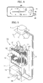
- the GHP comprises mainly the indoor unit 1 and the outdoor unit 10.
- the indoor unit 1 comprises the indoor heat exchange apparatus.
- the indoor heat exchange apparatus evaporates a liquid refrigerant of low temperature and low pressure, and thereby absorbs heat from the indoor air, that is, it cools the indoor air.
- the liquid refrigerant of low temperature and low pressure is supplied to the indoor heat exchange apparatus through the refrigerant pipe 2 from the outdoor unit 10 explained below.
- the indoor heat exchange apparatus condenses and liquefies a gaseous refrigerant of high temperature and high pressure, and thereby discharges heat to the indoor air, that is, it warms the indoor air.
- the gaseous refrigerant of high temperature and high pressure is supplied to the indoor heat exchange apparatus through the refrigerant pipe 2 from the outdoor unit 10 explained below.
- the indoor air is sucked by the indoor fan which is not shown in the figures, passes through the indoor heat exchange apparatus and thereby exchanges heat with the refrigerant. After that, the indoor air is blown out in the air-conditioned chamber.
- the outdoor unit 10 comprises a refrigerant circuit which comprises a compressor, an outdoor heat exchange apparatus, an expansion valve, and a four-way valve and a gas engine portion which comprises a gas engine for driving the compressor, an electric motor, and auxiliary equipment.
- the inside of the outdoor unit 10 is divided into top and bottom parts by a partition which is not shown in FIG. 9.
- the bottom part of the outdoor unit 10 is the machine chamber 11 which comprises mainly the gas engine 14, the compressor 15, and the controller 16.
- the top part of the outdoor unit 10 is a heat exchange chamber 12 which comprises mainly the outdoor heat exchange apparatus 30, and the outdoor fan 31.
- a ventilation opening is formed at the partition, and thereby the machine chamber 11 is connected to the heat exchange chamber 12.
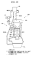
- FIG. 10 shows the flow of the blowby gas in the gas engine 14.
- the gas engine 14 comprises the oil pan 14a, the crank shaft 14b, the piston 14c, the piston ring 14d, the cylinder 14e, the crank case 14f, the combustion chamber 14g, the cylinder head cover 14h, and the intake manifold 14i.
- the blowby gas is gas which leaks from the combustion chamber 14g into the crank case 14f by passing through the gap between the piston ring 14d and the cylinder 14e, and it contains the combustible fuel, the lubricating oil in the state of a mist, the discharge gas, and the like.
- the blowby gas containing the oil mist which descends into the crank case 14f passes through the passage BG1 and is introduced into the cylinder head cover 14h.
- the cylinder head cover 14h is connected to the blowby gas filter 40 via the outflow passage BG2. Due to this structure, the blowby gas is introduced into the blowby gas filter 40 from the cylinder head cover 14h.
- the oil which is separated from the blowby gas by the blowby gas filter 40 passes through the oil return hose BG3 due to its own weight and is returned into the oil pan 14a. Then the oil is mixed with the lubricating oil in the oil pan 14a, and used again.
- the blowby gas from which the oil mist has been separated by the blowby gas filter 40 passes through the blowby gas return passage BG4 and is then taken into a portion of the engine intake system, such as the intake manifold 14i.
- the blowby gas which has been taken into the intake manifold 14i is mixed with new air which is shown by an arrow with a line, returns into the combustion chamber 14g, and it is burned with the fuel gas.
- the blowby gas filter 40 which is used as an oil separator can have the following structure.
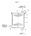
- the blowby gas filter 40 of this embodiment comprises the hollow case body 41 comprising the opening at the top thereof, the lid 42 for covering the opening formed in the case body 41, and the filter 43 which is made of nonwoven fabrics and is put into the case body 41.
- reference numeral 44 denotes the entrance for inward flow of the blowby gas containing the oil mist
- 45 denotes the exit for outward flow of the blowby gas in which the oil mist has been separated
- 46 denotes the outflow exit for outward flow of the separated oil.
- the case body 41 has a hollow rectangular shape, and is made of synthetic resins. At the top of the case body 41, an opening is provided. Around the opening, the flange 41a is provided.
- the lid 42 is a plate member made of synthetic resins having a size approximately equal to the flange 41a.
- the case body 41 and the lid 42 are fixed by covering the opening with the lid 42 and bolting them together using the fixing members 47.
- the fixing member 47 members, which can removably attach the lid 42, such as a bolt and a nut, can be used.
- the O-ring 48 which is a seal member is provided in the flange 41a.
- the case body 41 comprises the entrance 44 for inward flow of the blowby gas containing the oil mist, and the outflow exit 46 for outward flow of the oil which has been separated and removed from the blowby gas.
- the blowby gas entrance 44 is provided at the lower side of the case body 41, and connected to the crank case 14f of the gas engine 14 via a pipe.
- the outflow exit 46 is provided at the bottom of the case body 41 so as to accumulate the oil which descends due to its own weight, and connected to the oil pan 14a via a pipe.
- the blowby gas entrance 44 and the outflow exit 46 are provided in a positive pressure region P1 which is formed below the filter 43. Since the positive pressure region P1 is connected to the crank case 14f, the pressure in the positive pressure region P1 is greater than the pressure outside of the case body 41, i.e., greater than the atmospheric pressure.
- the exit 45 for discharging the blowby gas which has been separated the oil mist from the case body 41 is provided. Since the exit 45 is connected to the intake system of the gas engine 14, such as the intake manifold 14i via a pipe, it is formed in a negative pressure region P2 where the pressure is lower than the atmospheric pressure.
- the blowby gas filter 40 As it passes through the filter 43, the oil which has been separated and removed from the blowby gas descends due to its own weight toward the bottom of the case body 41. Then, the oil passes through the outflow exit 46 and returns into the oil pan 14a.
- the case body 41 and the lid 42 do not come into contact with each other at the bottom of the case body 41, where the separated oil descends. Therefore, it is possible to solve the problem that the separated and removed oil leaks at the contact portion between the case body 41 and the lid 42.
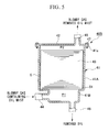
- the blowby gas filter 40A of this embodiment further comprises a guide member for introducing the gaseous fluid, that is a guide member for introducing the blowby gas into the center of the filter 43.
- the plate ring member 50 is provided so as to be integrated with the inside wall of the case body 41.
- the plate ring member 50 has a doughnut shape, and comprises a passage for the blowby gas at the center thereof.
- the plate ring member 50 is provided slightly above the entrance 44 for inward flow of the blowby gas.
- the plate ring member 50 can be also used as a supporting member for the filter 43, as shown in FIG. 4.
- blowby gas filter 40A since the plate ring member 50 is provided, the blowby gas cannot flow along the inside wall of the case body 41. As a result, the blowby gas containing the oil mist, which is introduced into the blowby gas filter 40A from the entrance 44, rises as it is introduced into the center of the filter 43. Thereby, all or almost of the blowby gas can be made to pass through the filter 43, and flows out from the exit 45. Consequently, in the blowby gas filter 40A of this embodiment, it is possible to separate and remove the oil mist with certainty from the blowby gas.
- the size of the hole which is formed at the center of the plate ring member 50 is too large, a large amount of the blowby gas passes through the gap S. In contrast, if it is too small, the separation efficiency can be improved, but the pressure loss increases. Therefore, it is preferable for the size of the hole which is formed at the center of the plate ring member 50 to be adjusted in accordance with the conditions.
- the blowby gas filter 40B of this embodiment is a modified embodiment of the blowby gas filter 40A in the second embodiment shown in FIG. 4.
- a connection portion 51 is used in this embodiment, which connects a large upper portion 41A and a small lower portion 41B.
- the case body 41 comprises the large upper portion 41A and the small lower portion 41B. They are connected by the connection portion 51.
- the connection portion 51 is a plate member which protrudes approximately horizontally toward the inside of the case body 41 between the large upper portion 41A and the small lower portion 41B.
- the plate member acts as the plate ring member 50 in the second embodiment.
- the connection portion 51 is also used as a support member for supporting the filter 43, similar to the plate ring member 50 in the second embodiment.
- the blowby gas filter 40B since the case body 41 comprises the connection portion 51, the blowby gas containing the oil mist which flows in through the entrance 44 is introduced into the center of the filter 43 as it rises. That is, since the gap S between the inside wall of the case body 41 the filter 43 is closed with the connection portion 51, all or almost of the blowby gas can be made to pass through the filter 43 and flows out from the exit 45. Consequently, in the blowby gas filter 40B of this embodiment, it is possible to separate and remove the oil mist with certainty from the blowby gas.
- the size of the hole which is formed at the center of the connection portion 51 i.e., the size of the small lower portion 41B
- the size of the hole which is formed at the center of the connection portion 51 is adjusted in accordance with the conditions.
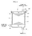
- the blowby gas filter 40C of this embodiment is a modified embodiment of the blowby gas filter 40A in the second embodiment shown in FIG. 4.
- a cylindrical member 52 is used, which is provided at the bottom surface of the lid 42 so as to protrude toward the inside of the case body 41.
- the cylindrical member 52 has a sectional shape which is similar to and smaller than that of the case body 41, and it contacts the filter 43. It is preferable for the cylindrical member 52 to be provided so that the bottom surface of the cylindrical member 52 contacts closely the top surface of the filter 43, as shown in FIG. 6.
- blowby gas filter 40C since the cylindrical member 52 is provided, the blowby gas containing the oil mist which passes through the gap S between the inside wall of the case body 41 the filter 43 cannot reach the negative pressure region P2 which is connected to the exit 45. Therefore, the blowby gas containing the oil mist which flows through the entrance 44 is introduced into the center of the filter 43 which contacts the negative pressure region P2 as it rises. Therefore, all or almost of the blowby gas can be made to pass through the filter 43 and flows out from the exit 45. Consequently, in the blowby gas filter 40C of this embodiment, it is possible to separate and remove the oil mist with certainty from the blowby gas.
- the lid 42 which is used to change the filter 43 is provided above the case body 41, it is possible to prevent the oil which has been separated and removed from the blowby gas by the filter 43 from leaking at the contact portion between the case body 41 and the lid 42.
- the structure of the seal for the contact portion between the case body 41 and the lid 42 is simple, they can be easily formed at a low cost.
- the oil separator of the present invention is used for the gaseous fluid, such as the blowby gas, since the entrance 44 is provided in a positive pressure region P1 and the exit 45 is formed in a negative pressure region P2, the contact portion between the case body 41 and the lid 42 is provided in the negative pressure region P2. As a result, it is possible to prevent the oil from leaking with more certainty.
- the gaseous fluid such as the blowby gas
- the guide member such as the plate ring member 50, connection portion 51, or the cylindrical member 52
- the guide member such as the plate ring member 50, connection portion 51, or the cylindrical member 52
- the oil separators of the present invention are used for the blowby gas of the gas engine 14 comprising the GHP. That is, the oil separator of the present invention is explained as a blowby gas filter.
- the oil separators of the present invention are not specifically limited to the above embodiments.
- the blowby gas exit of the oil separators of the present invention can be provided the place of which the pressure is not smaller than the atmospheric pressure.
- the present invention is not limited to the above embodiments, and the constitution of the oil separator according to the present invention can be changed as far as the change of the constitution is within the scope of the present invention.
- the structure for preventing oil leaks in the first embodiment and the structure for improving the oil separation efficiency in the second, third, and fourth embodiments can be adopted individually. However, if these structures are used together, it is possible to further improve the performance of the oil separator.
- FIGS. 7A and 7B the fifth embodiment of the blowby gas filter according to the present invention will be explained referring to FIGS. 7A and 7B.
- the blowby gas filter 40D comprises the hollow case body 41 comprising the opening at the top thereof, the lid 42 for covering the opening formed in the case body 41, and the filter 43 which is made of nonwoven fabrics and is put into the case body 41.
- the casing of the blowby gas filter 40 comprises the case body 41 and the lid 42.
- reference numeral 44 denotes the entrance for inward flow of the blowby gas containing the oil mist
- 45 denotes the exit for outward flow of the blowby gas in which the oil mist has been separated
- 46 denotes the outflow exit for outward flow of the separated oil.
- the case body 41 has a hollow rectangular shape, and is made of synthetic resins. At the top of the case body 41, an opening is provided. Around the opening, the flange 41a is provided.
- the lid 42 is a plate member made of synthetic resins having a size approximately equals to the flange 41a.
- the case body 41 and the lid 42 are fixed by covering the opening with the lid 42 and bolting them together using the fixing members 47.
- the fixing member 47 members, which can removably attach the lid 42, such as a bolt and a nut, can be used.
- the O-ring 48 which is a seal member is provided in the flange 41a.
- the case body 41 comprises the entrance 44 for flowing of the blowby gas containing the oil mist into the casing and the outflow exit 46 for outward flow of the oil which has been separated and removed from the blowby gas, which are provided at the circular flow formation portion 41L below the filter 43.
- the filter portion 41M for positioning the filter 43 is provided above the circular flow formation portion 41L.
- the blowby gas entrance 44 is provided at the lower side of the case body 41, and connected to the crank case 14f of the gas engine 14 via a pipe. Specifically, as shown in FIG. 7A, the entrance 44 is provided at short side of the case body 41 so that it contacts to the long side of the circular flow formation portion 41L and the center thereof does not meet to the center of the short side of the circular flow formation portion 41L. Due to this position, the blowby gas flowing through the entrance 44 flows into the casing along the long side of the circular flow formation portion 41L.
- the outflow exit 46 is provided at the bottom of the case body 41 so as to accumulate the oil which descends its own weight and discharge, and it is connected to the oil pan 14a via a pipe.
- the pressure of the circular flow formation portion 41L is greater than the pressure outside of the casing, i.e., greater than the atmospheric pressure. That is, the circular flow formation portion 41L is provided in a positive pressure region.
- the blowby gas exit 45 for discharging the blowby gas from which the oil has been separated and removed from the casing is provided. Since the blowby gas exit 45 is connected to the intake system of the gas engine 14, such as the intake manifold 14i via a pipe, it is formed in a negative pressure region P2 of which the pressure is lower than the atmospheric pressure.
- the circular flow formation portion 41L make the flow of the blowby gas circulate, it can separate the oil mist from the blowby gas by the centrifugal force.
- the oil mist which has a weight greater than that of the gas contained in the blowby gas, moves outwardly and adheres to the inside wall of the case body 41. Then, the oil mist descends to the bottom of the casing due to its own weight.
- the gas contained in the blowby gas which has a weight smaller than that of the oil mist, is separated from the oil mist, circulates near the center of the filter 43 as it rises.
- the gas passes through the filter 43, flows out through the blowby gas exit 45 which is provided in a negative pressure region, and flows into the intake manifold 14i.
- the oil mist which has not been separated by the circular flow formation portion 41L is absorbed in the filter 43, and thereby it is separated and removed.
- the circular flow formation portion 41L and the filter portion 41M are provided together. Therefore, the oil mist is separated from the blowby gas due to the effects provided by the circular flow formation portion 41L and the filter 43.
- the pressure loss of the blowby gas filter 40D of this embodiment is significantly smaller than that of the conventional blowby gas filter in which the thickness of the filter increases in order to obtain the oil mist separation efficiency which substantially equals to that of the blowby gas filter 40D.
- the flow of the blowby gas is made circulate only by providing the entrance 44 so that the center of the entrance 44 does not meet to the center of the short side of the circular flow formation portion 41L.
- the separation member 50 having a long cross-section at the vicinity of the circular flow formation portion 41L, in order to assist the formation of the circular flow of the blowby gas. If such separation member 50 is provided, the blowby gas which flows in through the entrance 44 easily circulates along the separation member 50. Beside the separation member 50 shown in FIG. 8, a plane guide or a curved guide may be provided at the suitable position, such as a corner of the circular flow formation portion 41L.
- the circular flow formation portion 41L it is preferable for the circular flow formation portion 41L to curve the comers thereof. Thereby, it is possible to make the flow of the blowby gas more smoothly.
- the cross section of the circular flow formation portion 41L in order to make the flow of the blowby gas circulate, it is preferable for the cross section of the circular flow formation portion 41L to be an oval, and more preferable is a circle.
- the cross section of the circular flow formation portion 41L may be preferably a rectangular shape or a rectangular shape of which the comers are curved.
- blowby gas exit 45 is provided at the center of lid 42 as shown by an imaginary lin e in FIG. 8. Due to this, it is also possible to form the smooth flow of the blowby gas. Since the flow of the blowby gas passes through the center of filter 43 and flows out through the blowby gas exit 44, the oil mist can be separated and removed by the filter 43 with certainty.
- the blowby gas filter 4D is used for separating blowby gas of the gas engine 14 comprising the GHP.
- the present invention is not limited to the oil separator for the gas engine comprising the GHP.
- the present invention can include the oil separator in which the exit is not provided in a negative pressure region.
- the present invention is not limited to the above embodiment, and the constructions of the oil separator according to the present invention can be changed as far as the change of the constructions is within the scope of the present invention.
- the lid 42 may be provided at the side surface of the casing as shown in FIG. 11.
Landscapes
- Engineering & Computer Science (AREA)
- Mechanical Engineering (AREA)
- General Engineering & Computer Science (AREA)
- Lubrication Details And Ventilation Of Internal Combustion Engines (AREA)
Abstract
An object of the present invention is to provide an oil separator which can be
manufactured at a low cost and can prevent the leakage of removed oil, and an oil
separator which has improved separation efficiency of the oil mist without increasing the
pressure loss; in order to achieve the object, the present invention provide an oil separator
for separating oil from a gaseous fluid containing oil in the state of a mist comprising: a
hollow case body comprising an opening at the top thereof; a lid for covering the opening
formed at the case body; and a filter in the case body; wherein an entrance for inward flow
of the gaseous fluid into the case body is formed at the lower side of the case body, an exit
for outward flow of the gaseous fluid is formed at the lid, and an outflow exit for outward
flow of oil which has been separated is formed at the bottom of the case body.
Description
The present invention relates to an oil separator for separating the oil mist from
gaseous fluids, such as a blowby gas, and in particular, to an oil separator which is
suitably used in a gas engine for a gas heat pump type air conditioner.
An air conditioner, in which a heat pump is used for cooling and heating
operations, is provided with a refrigerant circuit comprising an indoor heat exchange
apparatus, a compressor, an outdoor heat exchange apparatus, an expansion valve, etc.
When the refrigerant circulates in the refrigerant circuit and exchanges heat with air in the
indoor heat exchange apparatus and the outdoor heat exchange apparatus, the air
conditioned chamber is heated or cooled. In addition, in order to heat the chamber, not
only the outdoor heat exchange apparatus but also a refrigerant heating apparatus for
heating the refrigerant directly is sometimes provided in the refrigerant circuit.
In recent years, an air conditioner has been suggested, which comprises a gas
engine, instead of an ordinary motor, as a driving source for the compressor provided in
the refrigerant circuit. An air conditioner utilizing a gas engine is called a gas heat pump
type air conditioner (abbreviated as "GHP" below). The GHP can use gas, which is
relatively cheap, as fuel; therefore, the running cost thereof can be reduced, compared
with an air conditioner comprising a compressor driven by the ordinary motor
(abbreviated as "EHP" below).
Moreover, in the GHP, when waste heat of gas at a high temperature discharged
from the gas engine during the heating operation is used as the heat source for the
refrigerant, the heating ability can be improved, and the use efficiency of energy can also
be improved. In addition, when the waste heat of the gas discharged from the gas engine
is used in the GHP, the GHP does not require a special device, such as the refrigerant
heating device explained above.
Furthermore, the GHP can utilize the engine waste heat to defrost the outdoor
heat exchange apparatus during the heating operation. In general, the EHP defrosts the
outdoor heat exchange apparatus by stopping the heating operation and temporarily
performing the cooling operation. That is, when the EHP defrosts, cooled air is
introduced into the chamber. Therefore, a person in the chamber feels unpleasant. In
contrast, the GHP can utilize the waste heat, and it can continuously perform the heating
operation without such the problem which is caused by the EHP.
The GHP has many advantages as explained above; however, it also has the
following problems.
As explained above, the GHP uses the gas engine as a driving source for the
compressor. In the gas engine, oil contained in the blowby gas may rise to problems.
The blowby gas is gas which leaks from the combustion chamber into a crank case
through a gap between the piston ring and the cylinder. In general, the blowby gas is
returned from the crank case into an engine intake system and is then sent to the
combustion chamber again.
Since the blowby gas contains a lubricating oil in a the state of a mist
(abbreviated as "oil mist" below), at a suitable positions on a line for the flow of the
blowby gas (abbreviated as "blowby gas line" below), oil separators for accumulating and
removing the oil mist, such as a blowby gas filter, are provided.
FIGS. 11, 12A, and 12B show a conventional oil separator which is used as a
blowby gas filter. In the figures, reference number 140 denotes an oil separator, 141
denotes a case body, 142 denotes a lid, 143 denotes a filter, 144 denotes gaseous fluid
entrance, 145 denotes a gaseous fluid exit, and 146 denotes an outflow exit for the oil mist
accumulated by the filter 143. Moreover, the case body 141 and the lid 142 comprise the
casing of the oil separator 140.
In the oil separator 140, the blowby gas, which flows in through the entrance 144
connected to the crank case of the gas engine, passes through the filter 143 and is sucked
through the exit 145 by the intake system of the gas engine. The oil mist contained in the
blowby gas is separated and removed as it passes through the filter 143, falls to the bottom
of the case body 141, and is then returned to the oil pan of the gas engine through the
outflow exit 146. In the oil separator 140, in order to improve the separation efficiency
of the oil mist, the height of the filter 143, through which the blowby gas passes, is
increased as much as possible. It is necessary to replace the filter 143 after a given
operation time of the oil separator 140. Therefore, in order to change the filter 143, the
lid 142 can detach from the case body 141. In addition, in order to easily change the
filter 143, the lid 142 is attached at the side of the case body 141, where an opening
having the largest area can be formed.
However, if the lid 142 is formed at the side of the case body 141, there is the
possibility that the oil falling to the bottom of the case body 141 will leak from a gap
between the case body 141 and the lid 142. In particular, when the oil mist contained in
the blowby gas is separated and removed in the oil separator 140, the pressure at the
bottom of the case body 141 where the outflow exit 146 is provided is greater than the
atmospheric pressure at the outside of the case body 141. That is, the pressure at the
bottom of the case body 141 where the outflow exit 146 is provided in a positive pressure
region. Therefore, there may be oil leak due to the pressure difference, at any gap
occurring at the contact portion.
An oil leakage can be solved by improving the seal between the case body 141
and the lid 142. However, in order to obtain a good seal, the structure of the contact
portion must be complicated; therefore, a cost for manufacturing the oil separator will
increase. In addition, since the case body 141 and the lid 142 are made of synthetic
resins, if the structure thereof is complicated, their formability may be decreased.
In addition, in the conventional oil separator 140, since the filter 143 is made of
nonwoven fabrics, which have inferior shape maintaining properties, there is the problem
that a gap S can easily occur between the filter 143 and the inside wall of the case body
141, as shown in FIG. 12A. If the gap S is generated, the blowby gas containing the oil
mist passes through the gap S and flows out through the exit 145, without passing through
the filter 143. The gap S decreases the separation efficiency of the oil mist in the oil
separator 140. Therefore, it is desired for the blowby gas to pass with certainty through
the filter 143. In addition, in the conventional oil separator 140, since the separation of
the oil mist is carried out by only the filter 143, there is the problem that it is difficult to
obtain a sufficient separation efficiency. In this case, the separation efficiency can be
improved by increasing the thickness of the filter 143. However, an increase in the
thickness of the filter 143 causes a significant pressure loss. Therefore, the separation
efficiency cannot be sufficiently improved only by increasing the thickness of the filter
143. In the light of the above, it is desired to provide oil separator in which the oil mist
contained in the blowby gas can be efficiently separated without increasing the pressure
loss.
Therefore, one of objects of the present invention is to improve the performances
of the oil separator for removing the oil mist from the gaseous fluids, such as the blowby
gas. In particular, an object of the present invention is to provide an oil separator which
can be manufactured at a low cost and can prevent the leakage of removed oil, and an oil
separator which has improved separation efficiency of the oil mist contained in the
gaseous fluids without increasing the pressure loss.
In order to achieve the object, the present invention provides an oil separator for
separating oil from a gaseous fluid containing oil in the state of a mist comprising: a
hollow case body comprising an opening at the top thereof; a lid for covering the opening
formed at the case body; and a filter in the case body; wherein an entrance for flowing of
the gaseous fluid into the case body is formed at the lower side of the case body, an exit
for outward flow of the gaseous fluid is formed at the lid, and an outflow exit for outward
flow of oil which has been separated is formed at the bottom of the case body.
In the oil separator, since the opening, which is formed at the top of the case body,
is covered with the lid, the case body and the lid do not come into contact with each other
at the bottom of the case body, i.e., at the portion to which the separated oil descends.
Therefore, it is possible to flow out with certainty the separated and removed oil from the
oil separator without oil leaks at the contact portion between the case body and the lid.
In addition, the separator has a simple structure and it can be manufactured at a low cost.
In the oil separator, it is preferable to provide a guide for introducing the gaseous
fluid flowing from the entrance to the exit into the center of the filter.
In the oil separator, since the gaseous fluid is introduced into the center of the
filter by the guide, the amount of the gaseous fluid which does not pass through the filter
can be significantly decreased. If there is a gap between the filter and the inside wall of
the case body, it is possible to improve the separation efficiency of the oil mist.
In the oil separator, it is preferable for the guide to be a cylindrical member
provided at the bottom surface of the lid so as to protrude toward the inside of the case
body, or to be a plate ring member provided at the inside wall of the case body above the
entrance so as to protrude toward the inside of the case body.
In addition, in the oil separator, it is preferable for the case body to comprise a
large upper portion in which the filter is placed and a small lower portion in which the
entrance and the outflow exit are provided, and for the gaseous fluid flowing from the
entrance to the exit to be introduced into the center of the filter at a connection portion
between the large upper portion and the small lower portion.
In the oil separator, since the connection portion between the large upper portion
and the small lower portion acts as a guide for introducing the gaseous fluid into the center
of the filter, if there is the gap between the filter and the case body and the lid, it is
possible to improve the separation efficiency of the oil mist.
In the oil separator, it is preferable for the gaseous fluid entrance and the outflow
exit for the separated oil to be formed in a positive pressure region, and for the gaseous
fluid exit to be formed in a negative pressure region.
If the gaseous fluid is a blowby gas for an internal combustion engine, the
positive pressure region is connected to the crank case of the internal combustion engine,
and the negative pressure region is connected to the intake system of the internal
combustion engine. Therefore, in the oil separator, since the contact portion between the
case body and the lid is formed in a negative pressure region, that is, the pressure at the
connection portion is lower than the pressure outside of the case body, i.e., lower than the
atmospheric pressure, the oil is less likely to leak from the oil separator.
In addition, if the oil separator is used to remove the oil mist from the blowby gas
of the internal combustion engine, since the gaseous fluid exit is connected to the intake
system, it is possible to easily form a negative pressure region.
In order to achieve the object, the present invention provides another oil separator
for separating oil from a gaseous fluid containing oil in the state of a mist comprising: a
circular flow formation portion for generating a circular flow of the gaseous fluid
introduced in the casing and a filter portion in which the circular flow of the gaseous fluid
passes.
In the oil separator, the oil mist is separated by the centrifugal force occurring
due to the circular flow formation portion and by passing through the filter. In other
words, the oil mist is separated from the gaseous fluid due to the effects provided by the
circular flow formation portion and the filter. Therefore, it is possible to improve the
separation efficiency without increasing the pressure loss.
In the oil separator, it is preferable to provide an entrance for inward flow of the
gaseous fluid at the lower side of a casing, an exit for outward flow of the gaseous fluid at
the top surface of the casing, an outflow exit for outward flow of the oil which has been
separated is formed at the bottom of the casing, and the circular flow formation portion is
provided at the lower portion of the casing.
In the oil separator, since the gaseous fluid passes through the circular flow
formation portion and thereby the amount of the oil mist contained in the gaseous fluid
decreases due to the centrifugal force, a gaseous fluid containing only a small amount of
oil mist passes through the filter. In addition, the oil removed by the centrifugal force
flows out the casing through the outflow exit without passing through the filter place
portion. Therefore, it is possible to increase the operation life of the filter. In addition,
oil separated and removed by the filter descends due to its own weight and flows out the
casing through the outflow exit.
In addition, it is preferable for the position and the direction of the opening of the
gaseous fluid entrance to be adjusted such that the gaseous fluid is introduced into the
casing along the inside wall of the casing. As a result, it is easy for the gaseous fluid to
form a circular flow.
In addition, it is also preferable to provide a circular flow formation guide for the
gaseous fluid in the circular flow formation portion. This makes it easy to form a
circular flow. Furthermore, it is also preferable for the gaseous fluid exit to be provided
at the center of the top surface of the casing. This makes it possible to generate the
circular flow of the gaseous fluid.
It is preferable for the gaseous fluid to be the blowby gas of the internal
combustion engine, for the gaseous fluid entrance to be connected to the crank case of the
internal combustion engine, and for the gaseous fluid exit to be connected to the intake
system of the internal combustion engine. Due to this, since the gaseous fluid pushed out
by the crank case at a positive pressure is taken into the intake system at a negative
pressure through the oil separator, it is possible to generate a smooth flow of the gaseous
fluid in the oil separator.
Referring the figures, preferred embodiments of the oil separator according to the
present invention will be explained below.
First, as the device which comprises the oil separator of the present invention, the
GHP will be explained.
As shown in FIG. 9, the GHP comprises mainly the indoor unit 1 and the outdoor
unit 10.
The indoor unit 1 comprises the indoor heat exchange apparatus. During the
cooling operation, the indoor heat exchange apparatus evaporates a liquid refrigerant of
low temperature and low pressure, and thereby absorbs heat from the indoor air, that is, it
cools the indoor air. The liquid refrigerant of low temperature and low pressure is
supplied to the indoor heat exchange apparatus through the refrigerant pipe 2 from the
outdoor unit 10 explained below.
During the heating operation, the indoor heat exchange apparatus condenses and
liquefies a gaseous refrigerant of high temperature and high pressure, and thereby
discharges heat to the indoor air, that is, it warms the indoor air. The gaseous refrigerant
of high temperature and high pressure is supplied to the indoor heat exchange apparatus
through the refrigerant pipe 2 from the outdoor unit 10 explained below.
Moreover, the indoor air is sucked by the indoor fan which is not shown in the
figures, passes through the indoor heat exchange apparatus and thereby exchanges heat
with the refrigerant. After that, the indoor air is blown out in the air-conditioned
chamber.
The outdoor unit 10 comprises a refrigerant circuit which comprises a compressor,
an outdoor heat exchange apparatus, an expansion valve, and a four-way valve and a gas
engine portion which comprises a gas engine for driving the compressor, an electric motor,
and auxiliary equipment.
The inside of the outdoor unit 10 is divided into top and bottom parts by a
partition which is not shown in FIG. 9. The bottom part of the outdoor unit 10 is the
machine chamber 11 which comprises mainly the gas engine 14, the compressor 15, and
the controller 16. The top part of the outdoor unit 10 is a heat exchange chamber 12
which comprises mainly the outdoor heat exchange apparatus 30, and the outdoor fan 31.
In addition, a ventilation opening is formed at the partition, and thereby the machine
chamber 11 is connected to the heat exchange chamber 12.
FIG. 10 shows the flow of the blowby gas in the gas engine 14. The gas engine
14 comprises the oil pan 14a, the crank shaft 14b, the piston 14c, the piston ring 14d, the
cylinder 14e, the crank case 14f, the combustion chamber 14g, the cylinder head cover
14h, and the intake manifold 14i. The blowby gas is gas which leaks from the
combustion chamber 14g into the crank case 14f by passing through the gap between the
piston ring 14d and the cylinder 14e, and it contains the combustible fuel, the lubricating
oil in the state of a mist, the discharge gas, and the like.
As shown by an arrow with broken lines in FIG. 10, the blowby gas containing
the oil mist which descends into the crank case 14f passes through the passage BG1 and is
introduced into the cylinder head cover 14h. The cylinder head cover 14h is connected
to the blowby gas filter 40 via the outflow passage BG2. Due to this structure, the
blowby gas is introduced into the blowby gas filter 40 from the cylinder head cover 14h.
In addition, as shown by an arrow with two-dot chain lines, the oil which is separated
from the blowby gas by the blowby gas filter 40 passes through the oil return hose BG3
due to its own weight and is returned into the oil pan 14a. Then the oil is mixed with the
lubricating oil in the oil pan 14a, and used again. As shown by an arrow with dashed
lines, the blowby gas from which the oil mist has been separated by the blowby gas filter
40 passes through the blowby gas return passage BG4 and is then taken into a portion of
the engine intake system, such as the intake manifold 14i. The blowby gas which has
been taken into the intake manifold 14i is mixed with new air which is shown by an arrow
with a line, returns into the combustion chamber 14g, and it is burned with the fuel gas.
The blowby gas filter 40 which is used as an oil separator can have the following
structure.
As shown in FIG. 1, the blowby gas filter 40 of this embodiment comprises the
hollow case body 41 comprising the opening at the top thereof, the lid 42 for covering the
opening formed in the case body 41, and the filter 43 which is made of nonwoven fabrics
and is put into the case body 41. In FIG. 4, reference numeral 44 denotes the entrance
for inward flow of the blowby gas containing the oil mist, 45 denotes the exit for outward
flow of the blowby gas in which the oil mist has been separated, and 46 denotes the
outflow exit for outward flow of the separated oil.
The case body 41 has a hollow rectangular shape, and is made of synthetic resins.
At the top of the case body 41, an opening is provided. Around the opening, the flange
41a is provided. In addition, as shown in FIG. 2, the lid 42 is a plate member made of
synthetic resins having a size approximately equal to the flange 41a. The case body 41
and the lid 42 are fixed by covering the opening with the lid 42 and bolting them together
using the fixing members 47. As the fixing member 47, members, which can removably
attach the lid 42, such as a bolt and a nut, can be used. In addition, as shown in FIG. 3,
the O-ring 48 which is a seal member is provided in the flange 41a.
The case body 41 comprises the entrance 44 for inward flow of the blowby gas
containing the oil mist, and the outflow exit 46 for outward flow of the oil which has been
separated and removed from the blowby gas. The blowby gas entrance 44 is provided at
the lower side of the case body 41, and connected to the crank case 14f of the gas engine
14 via a pipe. The outflow exit 46 is provided at the bottom of the case body 41 so as to
accumulate the oil which descends due to its own weight, and connected to the oil pan 14a
via a pipe. The blowby gas entrance 44 and the outflow exit 46 are provided in a positive
pressure region P1 which is formed below the filter 43. Since the positive pressure
region P1 is connected to the crank case 14f, the pressure in the positive pressure region
P1 is greater than the pressure outside of the case body 41, i.e., greater than the
atmospheric pressure.
At the lid 42, the exit 45 for discharging the blowby gas which has been separated
the oil mist from the case body 41 is provided. Since the exit 45 is connected to the
intake system of the gas engine 14, such as the intake manifold 14i via a pipe, it is formed
in a negative pressure region P2 where the pressure is lower than the atmospheric
pressure.
In the blowby gas filter 40, as it passes through the filter 43, the oil which has
been separated and removed from the blowby gas descends due to its own weight toward
the bottom of the case body 41. Then, the oil passes through the outflow exit 46 and
returns into the oil pan 14a. In the blowby gas filter 40, the case body 41 and the lid 42
do not come into contact with each other at the bottom of the case body 41, where the
separated oil descends. Therefore, it is possible to solve the problem that the separated
and removed oil leaks at the contact portion between the case body 41 and the lid 42.
In addition, in the oil separator 40, since the contact portion between the case
body 41 and the lid 42 is formed in the negative pressure region P2 which is above the
filter 43, the oil is less likely to leak from the oil separator.
Below, the second embodiment of the blowby gas filter according to the present
invention will be explained referring to FIG. 4.
In addition to the members comprising the blowby gas filter 40 of the first
embodiment, the blowby gas filter 40A of this embodiment further comprises a guide
member for introducing the gaseous fluid, that is a guide member for introducing the
blowby gas into the center of the filter 43. In this embodiment, as the guide member, the
plate ring member 50 is provided so as to be integrated with the inside wall of the case
body 41. The plate ring member 50 has a doughnut shape, and comprises a passage for
the blowby gas at the center thereof. The plate ring member 50 is provided slightly
above the entrance 44 for inward flow of the blowby gas. Moreover, the plate ring
member 50 can be also used as a supporting member for the filter 43, as shown in FIG. 4.
In the blowby gas filter 40A, since the plate ring member 50 is provided, the
blowby gas cannot flow along the inside wall of the case body 41. As a result, the
blowby gas containing the oil mist, which is introduced into the blowby gas filter 40A
from the entrance 44, rises as it is introduced into the center of the filter 43. Thereby, all
or almost of the blowby gas can be made to pass through the filter 43, and flows out from
the exit 45. Consequently, in the blowby gas filter 40A of this embodiment, it is possible
to separate and remove the oil mist with certainty from the blowby gas.
In other words, if there is a gap S between the inside wall of the case body 41 and
the filter 43, since the flow of the blowby gas containing the oil mist is introduced into the
center of the filter 43 by the plate ring member 50, it is possible to prevent for the blowby
gas from passing through the gap S. Thereby, the ratio of the blowby gas which contains
the oil mist and flows out from the blowby gas filter 40A with respect to the blowby gas
which flows into the blowby gas filter 40A can be significantly decreased. Therefore, it
is possible to significantly improve the oil separation efficiency of the blowby gas filter
40A.
In addition, if the size of the hole which is formed at the center of the plate ring
member 50 is too large, a large amount of the blowby gas passes through the gap S. In
contrast, if it is too small, the separation efficiency can be improved, but the pressure loss
increases. Therefore, it is preferable for the size of the hole which is formed at the center
of the plate ring member 50 to be adjusted in accordance with the conditions.
Below, the third embodiment of the blowby gas filter according to the present
invention will be explained referring to FIG. 5.
The blowby gas filter 40B of this embodiment is a modified embodiment of the
blowby gas filter 40A in the second embodiment shown in FIG. 4. Specifically, as the
guide member for introducing the blowby gas into the center of the filter 43, a connection
portion 51 is used in this embodiment, which connects a large upper portion 41A and a
small lower portion 41B. In other words, in this embodiment, the case body 41
comprises the large upper portion 41A and the small lower portion 41B. They are
connected by the connection portion 51. That is, the connection portion 51 is a plate
member which protrudes approximately horizontally toward the inside of the case body 41
between the large upper portion 41A and the small lower portion 41B. The plate
member acts as the plate ring member 50 in the second embodiment. In addition, the
connection portion 51 is also used as a support member for supporting the filter 43, similar
to the plate ring member 50 in the second embodiment.
In the blowby gas filter 40B, since the case body 41 comprises the connection
portion 51, the blowby gas containing the oil mist which flows in through the entrance 44
is introduced into the center of the filter 43 as it rises. That is, since the gap S between
the inside wall of the case body 41 the filter 43 is closed with the connection portion 51,
all or almost of the blowby gas can be made to pass through the filter 43 and flows out
from the exit 45. Consequently, in the blowby gas filter 40B of this embodiment, it is
possible to separate and remove the oil mist with certainty from the blowby gas.
In other words, if there is a gap S between the inside wall of the case body 41 and
the filter 43, since the flow of the blowby gas containing the oil mist gas is introduced into
the center of the filter 43 by the connection portion 51, it is possible to prevent for the
blowby gas from passing through the gap S. Thereby, the ratio of the blowby gas which
contains the oil mist and flows out the blowby gas filter 40B with respect to the blowby
gas which flows into the blowby gas filter 40B can be significantly decreased. As a
result, it is possible to significantly improve the oil separation efficiency of the blowby gas
filter 40B.
In addition, if the size of the hole which is formed at the center of the connection
portion 51, i.e., the size of the small lower portion 41B, is too large, a large amount of the
blowby gas passes through the gap S. In contrast, if it is too small, the separation
efficiency can be improved, but the pressure loss increases. Therefore, it is preferable for
the size of the hole which is formed at the center of the connection portion 51 to be
adjusted in accordance with the conditions.
Below, the fourth embodiment of the blowby gas filter according to the present
invention will be explained referring to FIG. 6.
The blowby gas filter 40C of this embodiment is a modified embodiment of the
blowby gas filter 40A in the second embodiment shown in FIG. 4. Specifically, as the
guide member for introducing the blowby gas into the center of the filter 43, a cylindrical
member 52 is used, which is provided at the bottom surface of the lid 42 so as to protrude
toward the inside of the case body 41. The cylindrical member 52 has a sectional shape
which is similar to and smaller than that of the case body 41, and it contacts the filter 43.
It is preferable for the cylindrical member 52 to be provided so that the bottom surface of
the cylindrical member 52 contacts closely the top surface of the filter 43, as shown in FIG.
6.
In the blowby gas filter 40C, since the cylindrical member 52 is provided, the
blowby gas containing the oil mist which passes through the gap S between the inside wall
of the case body 41 the filter 43 cannot reach the negative pressure region P2 which is
connected to the exit 45. Therefore, the blowby gas containing the oil mist which flows
through the entrance 44 is introduced into the center of the filter 43 which contacts the
negative pressure region P2 as it rises. Therefore, all or almost of the blowby gas can be
made to pass through the filter 43 and flows out from the exit 45. Consequently, in the
blowby gas filter 40C of this embodiment, it is possible to separate and remove the oil
mist with certainty from the blowby gas.
In other words, if there is a gap S between the inside wall of the case body 41 and
the filter 43, since the flow of the blowby gas containing the oil mist is introduced into the
center of the filter 43 by the cylindrical member 52, it is possible to prevent the blowby
gas from passing through the gap S. Thereby, the ratio of the blowby gas which contains
the oil mist and outward flows from the blowby gas filter 40C with respect to the blowby
gas which flows into the blowby gas filter 40C can be significantly decreased. As a
result, it is possible to improve the separation efficiency of the blowby gas filter 40C.
As explained above, in the blowby gas filter, that is, the oil separator of the
present invention, since the lid 42 which is used to change the filter 43 is provided above
the case body 41, it is possible to prevent the oil which has been separated and removed
from the blowby gas by the filter 43 from leaking at the contact portion between the case
body 41 and the lid 42. In addition, since the structure of the seal for the contact portion
between the case body 41 and the lid 42 is simple, they can be easily formed at a low cost.
In particular, if the oil separator of the present invention is used for the gaseous
fluid, such as the blowby gas, since the entrance 44 is provided in a positive pressure
region P1 and the exit 45 is formed in a negative pressure region P2, the contact portion
between the case body 41 and the lid 42 is provided in the negative pressure region P2.
As a result, it is possible to prevent the oil from leaking with more certainty.
In addition, if the guide member, such as the plate ring member 50, connection
portion 51, or the cylindrical member 52 is provided, it is possible to solve the problem
that the blowby gas containing the oil mist passes through the gap S between the inside
wall of the case body 41 and the filter 43, without passing through the filter 43 and flows
out from the exit 45. That is, all or almost of the blowby gas can be made to pass
through the filter 43 and flows out from the exit 45. Consequently, in the blowby gas
filter of the present invention, it is possible to separate and remove the oil mist with
certainty from the blowby gas. Thereby, the oil separation efficiency of the oil separator
can be improved. In other words, if there is a gap S between the inside wall of the case
body 41 and the filter 43, the amount of the blowby gas passing through the gap S is
significantly decreased. Therefore, deterioration of oil separation efficiency decrease
due to this can be prevented.
In the above, the oil separators of the present invention are used for the blowby
gas of the gas engine 14 comprising the GHP. That is, the oil separator of the present
invention is explained as a blowby gas filter. However, the oil separators of the present
invention are not specifically limited to the above embodiments. The blowby gas exit of
the oil separators of the present invention can be provided the place of which the pressure
is not smaller than the atmospheric pressure. In addition, the present invention is not
limited to the above embodiments, and the constitution of the oil separator according to
the present invention can be changed as far as the change of the constitution is within the
scope of the present invention.
In addition, the structure for preventing oil leaks in the first embodiment and the
structure for improving the oil separation efficiency in the second, third, and fourth
embodiments can be adopted individually. However, if these structures are used together,
it is possible to further improve the performance of the oil separator.
Below, the fifth embodiment of the blowby gas filter according to the present
invention will be explained referring to FIGS. 7A and 7B.
As shown in FIG. 7B, the blowby gas filter 40D comprises the hollow case body
41 comprising the opening at the top thereof, the lid 42 for covering the opening formed in
the case body 41, and the filter 43 which is made of nonwoven fabrics and is put into the
case body 41. Moreover, the casing of the blowby gas filter 40 comprises the case body
41 and the lid 42. In addition, in FIGS. 7A and 7B, reference numeral 44 denotes the
entrance for inward flow of the blowby gas containing the oil mist, 45 denotes the exit for
outward flow of the blowby gas in which the oil mist has been separated, and 46 denotes
the outflow exit for outward flow of the separated oil.
The case body 41 has a hollow rectangular shape, and is made of synthetic resins.
At the top of the case body 41, an opening is provided. Around the opening, the flange
41a is provided. In addition, as shown in FIGS. 7A and 7B, the lid 42 is a plate member
made of synthetic resins having a size approximately equals to the flange 41a. The case
body 41 and the lid 42 are fixed by covering the opening with the lid 42 and bolting them
together using the fixing members 47. As the fixing member 47, members, which can
removably attach the lid 42, such as a bolt and a nut, can be used. In addition, as shown
in FIG. 3, the O-ring 48 which is a seal member is provided in the flange 41a.
The case body 41 comprises the entrance 44 for flowing of the blowby gas
containing the oil mist into the casing and the outflow exit 46 for outward flow of the oil
which has been separated and removed from the blowby gas, which are provided at the
circular flow formation portion 41L below the filter 43. In addition, in the case body 41,
the filter portion 41M for positioning the filter 43 is provided above the circular flow
formation portion 41L.
The blowby gas entrance 44 is provided at the lower side of the case body 41, and
connected to the crank case 14f of the gas engine 14 via a pipe. Specifically, as shown in
FIG. 7A, the entrance 44 is provided at short side of the case body 41 so that it contacts to
the long side of the circular flow formation portion 41L and the center thereof does not
meet to the center of the short side of the circular flow formation portion 41L. Due to
this position, the blowby gas flowing through the entrance 44 flows into the casing along
the long side of the circular flow formation portion 41L. In addition, the outflow exit 46
is provided at the bottom of the case body 41 so as to accumulate the oil which descends
its own weight and discharge, and it is connected to the oil pan 14a via a pipe.
Since the circular flow formation portion 41L in which the blowby gas entrance
44 and the outflow exit 46 are provided is connected to the crank case 14f, the pressure of
the circular flow formation portion 41L is greater than the pressure outside of the casing,
i.e., greater than the atmospheric pressure. That is, the circular flow formation portion
41L is provided in a positive pressure region.
At the lid 42, the blowby gas exit 45 for discharging the blowby gas from which
the oil has been separated and removed from the casing is provided. Since the blowby
gas exit 45 is connected to the intake system of the gas engine 14, such as the intake
manifold 14i via a pipe, it is formed in a negative pressure region P2 of which the pressure
is lower than the atmospheric pressure.
In the blowby gas filter 40D, since the circular flow formation portion 41L make
the flow of the blowby gas circulate, it can separate the oil mist from the blowby gas by
the centrifugal force. As a result, the oil mist, which has a weight greater than that of the
gas contained in the blowby gas, moves outwardly and adheres to the inside wall of the
case body 41. Then, the oil mist descends to the bottom of the casing due to its own
weight. In contrast, the gas contained in the blowby gas, which has a weight smaller than
that of the oil mist, is separated from the oil mist, circulates near the center of the filter 43
as it rises. As a result, the gas passes through the filter 43, flows out through the blowby
gas exit 45 which is provided in a negative pressure region, and flows into the intake
manifold 14i. The oil mist which has not been separated by the circular flow formation
portion 41L is absorbed in the filter 43, and thereby it is separated and removed.
As explained above, in the blowby gas filter 40D in this embodiment, the circular
flow formation portion 41L and the filter portion 41M are provided together. Therefore,
the oil mist is separated from the blowby gas due to the effects provided by the circular
flow formation portion 41L and the filter 43. In addition, the pressure loss of the blowby
gas filter 40D of this embodiment is significantly smaller than that of the conventional
blowby gas filter in which the thickness of the filter increases in order to obtain the oil
mist separation efficiency which substantially equals to that of the blowby gas filter 40D.
In addition, in this embodiment, the flow of the blowby gas is made circulate
only by providing the entrance 44 so that the center of the entrance 44 does not meet to the
center of the short side of the circular flow formation portion 41L. However, as shown
in FIG. 8, it is preferable to provide the separation member 50 having a long cross-section
at the vicinity of the circular flow formation portion 41L, in order to assist the formation
of the circular flow of the blowby gas. If such separation member 50 is provided, the
blowby gas which flows in through the entrance 44 easily circulates along the separation
member 50. Beside the separation member 50 shown in FIG. 8, a plane guide or a
curved guide may be provided at the suitable position, such as a corner of the circular flow
formation portion 41L. In addition, it is preferable for the circular flow formation
portion 41L to curve the comers thereof. Thereby, it is possible to make the flow of the
blowby gas more smoothly. In particular, in order to make the flow of the blowby gas
circulate, it is preferable for the cross section of the circular flow formation portion 41L to
be an oval, and more preferable is a circle. However, when the space required for
placing the blowby gas filter 40D is considered, the cross section of the circular flow
formation portion 41L may be preferably a rectangular shape or a rectangular shape of
which the comers are curved.
It is preferable for the blowby gas exit 45 to be provided at the center of lid 42 as
shown by an imaginary lin
e in FIG. 8. Due to this, it is also possible to form the smooth flow of the blowby gas.
Since the flow of the blowby gas passes through the center of filter 43 and flows out
through the blowby gas exit 44, the oil mist can be separated and removed by the filter 43
with certainty.
As explained above, the blowby gas filter 4D is used for separating blowby gas of
the gas engine 14 comprising the GHP. However, the present invention is not limited to
the oil separator for the gas engine comprising the GHP. For example, the present
invention can include the oil separator in which the exit is not provided in a negative
pressure region.
In addition, the present invention is not limited to the above embodiment, and the
constructions of the oil separator according to the present invention can be changed as far
as the change of the constructions is within the scope of the present invention. For
example, the lid 42 may be provided at the side surface of the casing as shown in FIG. 11.
Claims (13)
- An oil separator for separating oil from a gaseous fluid containing oil in the state of a mist comprising:wherein an entrance for inward flow of said gaseous fluid into said case body is formed at the lower side of said case body, an exit for outward flow of said gaseous fluid is formed at said lid, and an outflow exit for outward flow of oil which has been separated is formed at the bottom of said case body.a hollow case body comprising an opening at the top thereof;a lid for covering said opening formed at said case body; anda filter in said case body;
- An oil separator according to claim 1, wherein said oil separator further comprises a guide for introducing said gaseous fluid flowing from said entrance to said exit into the center of said filter.
- An oil separator according to claim 2, wherein said guide is a cylindrical member provided at the bottom surface of said lid so as to protrude toward the inside of said case body.
- An oil separator according to claim 2, wherein said guide is a plate ring member provided at the inside wall of said case body above said entrance so as to protrude toward the inside of said case body.
- An oil separator according to claim 1, wherein said case body comprises a large upper portion in which said filter is placed and a small lower portion in which said entrance and said outflow exit are provided, and a fluid of said gaseous fluid from said entrance to said exit is introduced into the center of said filter at a connection portion between said large upper portion and said small lower portion.
- An oil separator according to claim 1, wherein said entrance and said outflow exit are formed in a positive pressure region, and said exit is formed in a negative pressure region.
- An oil separator according to claim 6, wherein said gaseous fluid is a blowby gas for an internal combustion engine, said positive pressure region is connected to a crank case of an internal combustion engine, and said negative pressure region is connected to an intake system of said internal combustion engine.
- An oil separator for separating oil from a gaseous fluid containing oil in the state of a mist comprising:a circular flow formation portion for generating a circular flow of said gaseous fluid introduced in a casing; anda filter portion in which said circular flow of said gaseous fluid passes.
- An oil separator according to claim 8, wherein an entrance for inward flow of said gaseous fluid is provided at the lower side of said casing; an exit for outward flow of said gaseous fluid is provided at the top surface of said casing; an outflow exit for outward flow of said oil which has been separated is formed at the bottom of said casing; and said circular flow formation portion is provided at the lower portion of said casing.
- An oil separator according to claim 9, wherein the position and the direction of an opening of said entrance is adjusted such that said gaseous fluid is introduced into said casing along the inside wall of said casing.
- An oil separator according to claim 8, wherein said oil separator further comprises a guide for assisting a formation of said circular flow of said gaseous fluid at the circular flow formation portion.
- An oil separator according to claim 9, wherein said exit is provided at the center of the top surface of said casing.
- An oil separator according to claim 9, wherein said gaseous fluid is a blowby gas of an internal combustion engine, said entrance is connected to a crank case of said internal combustion engine, and said exit is connected to an intake system of said internal combustion engine.
Applications Claiming Priority (4)
| Application Number | Priority Date | Filing Date | Title |
|---|---|---|---|
| JP2001070088A JP2002266621A (en) | 2001-03-13 | 2001-03-13 | Oil separator structure |
| JP2001070088 | 2001-03-13 | ||
| JP2001070076 | 2001-03-13 | ||
| JP2001070076A JP3470805B2 (en) | 2001-03-13 | 2001-03-13 | Oil separator structure |
Publications (1)
| Publication Number | Publication Date |
|---|---|
| EP1241327A1 true EP1241327A1 (en) | 2002-09-18 |
Family
ID=26611128
Family Applications (1)
| Application Number | Title | Priority Date | Filing Date |
|---|---|---|---|
| EP02001593A Withdrawn EP1241327A1 (en) | 2001-03-13 | 2002-01-23 | Oil separator |
Country Status (5)
| Country | Link |
|---|---|
| US (1) | US6635095B2 (en) |
| EP (1) | EP1241327A1 (en) |
| KR (1) | KR100414774B1 (en) |
| CN (2) | CN1240934C (en) |
| AU (1) | AU2321802A (en) |
Cited By (1)
| Publication number | Priority date | Publication date | Assignee | Title |
|---|---|---|---|---|
| AU2004201305B2 (en) * | 2003-03-26 | 2005-07-28 | Komatsu Ltd. | Filter for Trapping Foreign Matter |
Families Citing this family (25)
| Publication number | Priority date | Publication date | Assignee | Title |
|---|---|---|---|---|
| DE10239408A1 (en) * | 2002-08-28 | 2004-03-11 | Robert Bosch Gmbh | Device for separating liquid from a gas stream |
| SG114657A1 (en) * | 2003-05-23 | 2005-09-28 | Fulta Electric Machinery Co | Oil mist removal device |
| US7285149B2 (en) * | 2003-10-31 | 2007-10-23 | Bendix Commercial Vehicle Systems Llc | Oil separator for vehicle air system |
| FR2867564B1 (en) * | 2004-03-11 | 2006-06-23 | Total France | METHOD AND DEVICE FOR REAL-TIME MEASUREMENT OF THE OIL CONSUMPTION OF THE ENGINE OIL SEPARATION SYSTEM |
| BE1016301A3 (en) * | 2004-11-08 | 2006-07-04 | Atlas Copco Airpower Nv | DEVICE FOR SEPARATING OIL FROM A BREED OF AN OIL RESERVOIR. |
| JP2006152890A (en) * | 2004-11-29 | 2006-06-15 | Toyota Industries Corp | Oil separating structure and internal combustion engine |
| CN101351626B (en) * | 2005-10-28 | 2012-05-23 | 唐纳森公司 | Suspended particle separator and method of use |
| CN100414077C (en) * | 2006-03-07 | 2008-08-27 | 潍柴动力股份有限公司 | Oil and gas separation device |
| EP1884651B1 (en) * | 2006-08-01 | 2009-09-30 | GM Global Technology Operations, Inc. | Oil separator for gas operated internal combustion engines |
| DE102006041213B4 (en) * | 2006-09-02 | 2017-06-29 | Mahle International Gmbh | Device for crank chamber ventilation |
| US8256405B2 (en) * | 2008-06-13 | 2012-09-04 | Kohler Co. | Breather assembly with standpipe for an internal combustion engine |
| US8505520B2 (en) * | 2011-08-17 | 2013-08-13 | GM Global Technology Operations LLC | Engine assembly including positive crankcase ventilation with oil surge protection |
| CN102434309B (en) * | 2011-09-29 | 2014-08-06 | 西安航空动力股份有限公司 | Working medium recycling system of solar Stirling engine |
| RU2482294C2 (en) * | 2011-11-10 | 2013-05-20 | Сергей Михайлович Кузьмин | Device for reduction of steams condensation in crankcase of internal combustion engine |
| CN104271949B (en) | 2012-02-27 | 2016-08-24 | 纳薄特斯克汽车零部件有限公司 | oil separator |
| CN104350247B (en) | 2012-02-27 | 2017-12-15 | 纳薄特斯克汽车零部件有限公司 | Oil eliminator |
| US10087798B2 (en) * | 2012-02-27 | 2018-10-02 | Nabtesco Automotive Corporation | Oil separator |
| CN104349829B (en) | 2012-05-10 | 2016-02-17 | 纳薄特斯克汽车零部件有限公司 | oil separator |
| IN2014MN02671A (en) | 2012-07-02 | 2015-08-28 | Nabtesco Automotive Corp | |
| CN103861373A (en) * | 2012-12-13 | 2014-06-18 | 南通中船机械制造有限公司 | Crude water filter |
| KR101511220B1 (en) * | 2013-11-29 | 2015-04-10 | 심서운 | Engine cleaning bypass system |
| JP6826009B2 (en) * | 2017-08-08 | 2021-02-03 | 株式会社ニフコ | Oil separator |
| CN109578109B (en) * | 2017-09-29 | 2021-05-18 | 上海汽车集团股份有限公司 | An engine oil and gas separator, a cyclone separation assembly and a control method thereof |
| JP6725604B2 (en) * | 2018-08-24 | 2020-07-22 | 本田技研工業株式会社 | Oil separator unit |
| CN112648043B (en) * | 2019-10-10 | 2022-03-22 | 上海汽车集团股份有限公司 | An automobile and its engine and oil-gas separator |
Citations (8)
| Publication number | Priority date | Publication date | Assignee | Title |
|---|---|---|---|---|
| DE1900827A1 (en) * | 1968-05-24 | 1969-12-04 | Ishida Koki Seisakusyo Kk | Automatic weighing device |
| US4269607A (en) * | 1977-11-07 | 1981-05-26 | Walker Robert A | Air-oil separator and method of separation |
| US4272371A (en) * | 1980-02-21 | 1981-06-09 | Fram-Israelson Enterprises | Lubricating oil filter-refiner for internal combustion engines |
| EP0353903A1 (en) * | 1988-07-19 | 1990-02-07 | Pall Corporation | Method for gas-liquid separation and filtration |
| US4920930A (en) * | 1983-06-30 | 1990-05-01 | Kubota Limited | System for blow-by gas return to the combustion chamber of an engine |
| US5335512A (en) * | 1991-03-28 | 1994-08-09 | K-Whit Tools, Inc. | Refrigerant recovery device |
| US6048376A (en) * | 1998-08-03 | 2000-04-11 | Ingersoll-Rand Company | Combination baffle and filter element system for removing oil from an oil/gas mixture |
| US6171355B1 (en) * | 1997-06-27 | 2001-01-09 | Donaldson Company, Inc. | Aerosol separator; and method |
Family Cites Families (4)
| Publication number | Priority date | Publication date | Assignee | Title |
|---|---|---|---|---|
| US3483677A (en) * | 1967-02-06 | 1969-12-16 | Herbert Pinto | Air cleaning device |
| JPH0332113A (en) | 1989-06-28 | 1991-02-12 | Mitsubishi Electric Corp | Semiconductor integrated circuit |
| US5586996A (en) * | 1994-05-12 | 1996-12-24 | Manookian, Jr.; Arman K. | Vapor separating device |
| US6500243B2 (en) * | 2001-02-02 | 2002-12-31 | Ingersoll-Rand Company | Compressor system including a separator tank with a separator element positioned therein |
-
2002
- 2002-01-23 EP EP02001593A patent/EP1241327A1/en not_active Withdrawn
- 2002-01-25 US US10/054,974 patent/US6635095B2/en not_active Expired - Fee Related
- 2002-03-08 CN CNB021071012A patent/CN1240934C/en not_active Expired - Fee Related
- 2002-03-08 CN CNA2005100093613A patent/CN1672763A/en active Pending
- 2002-03-11 KR KR10-2002-0012954A patent/KR100414774B1/en not_active Expired - Fee Related
- 2002-03-11 AU AU23218/02A patent/AU2321802A/en not_active Abandoned
Patent Citations (8)
| Publication number | Priority date | Publication date | Assignee | Title |
|---|---|---|---|---|
| DE1900827A1 (en) * | 1968-05-24 | 1969-12-04 | Ishida Koki Seisakusyo Kk | Automatic weighing device |
| US4269607A (en) * | 1977-11-07 | 1981-05-26 | Walker Robert A | Air-oil separator and method of separation |
| US4272371A (en) * | 1980-02-21 | 1981-06-09 | Fram-Israelson Enterprises | Lubricating oil filter-refiner for internal combustion engines |
| US4920930A (en) * | 1983-06-30 | 1990-05-01 | Kubota Limited | System for blow-by gas return to the combustion chamber of an engine |
| EP0353903A1 (en) * | 1988-07-19 | 1990-02-07 | Pall Corporation | Method for gas-liquid separation and filtration |
| US5335512A (en) * | 1991-03-28 | 1994-08-09 | K-Whit Tools, Inc. | Refrigerant recovery device |
| US6171355B1 (en) * | 1997-06-27 | 2001-01-09 | Donaldson Company, Inc. | Aerosol separator; and method |
| US6048376A (en) * | 1998-08-03 | 2000-04-11 | Ingersoll-Rand Company | Combination baffle and filter element system for removing oil from an oil/gas mixture |
Cited By (1)
| Publication number | Priority date | Publication date | Assignee | Title |
|---|---|---|---|---|
| AU2004201305B2 (en) * | 2003-03-26 | 2005-07-28 | Komatsu Ltd. | Filter for Trapping Foreign Matter |
Also Published As
| Publication number | Publication date |
|---|---|
| KR100414774B1 (en) | 2004-01-13 |
| CN1240934C (en) | 2006-02-08 |
| US20020129586A1 (en) | 2002-09-19 |
| CN1382899A (en) | 2002-12-04 |
| US6635095B2 (en) | 2003-10-21 |
| CN1672763A (en) | 2005-09-28 |
| KR20020081545A (en) | 2002-10-28 |
| AU2321802A (en) | 2002-09-19 |
Similar Documents
| Publication | Publication Date | Title |
|---|---|---|
| US6635095B2 (en) | Oil separator | |
| KR910017134A (en) | Air conditioner | |
| BRPI0513348B1 (en) | OIL COOLING AGENT MODULE | |
| EP2908061A1 (en) | Outdoor Unit of Air-Conditioner | |
| KR20060051599A (en) | Chillers for piston machines | |
| JP3470805B2 (en) | Oil separator structure | |
| CN214250231U (en) | Oil separator and air conditioning system | |
| CN112556254B (en) | Oil separator, air conditioning system | |
| CN112665202B (en) | Air conditioning system | |
| CN214371115U (en) | Air conditioning system | |
| JP2002266621A (en) | Oil separator structure | |
| US7066133B2 (en) | Cover plate for a crank case | |
| KR100819015B1 (en) | Oil Separator with Compressor | |
| JPH11270923A (en) | Outdoor machine unit and air conditioner | |
| CN214145888U (en) | Compressor with air suction flow channel | |
| JPH11247715A (en) | Gas engine device, outdoor unit, and air conditioner | |
| CN206257047U (en) | The inside oil baffle structure and the compressor with the oil baffle structure of compressor | |
| CN222108386U (en) | Cooling devices and electrical equipment | |
| CN215633939U (en) | Oil-gas separator device of compressor bearing box | |
| CN112556221A (en) | Evaporative cooling type direct expansion unit and control method thereof | |
| CN221548385U (en) | Forced lubrication device for oilless machine set | |
| JP3426657B2 (en) | Drain water treatment equipment | |
| JPH09126175A (en) | Package type oil cooling compressor | |
| JP3653365B2 (en) | Outdoor unit of engine-driven heat pump device | |
| CN118066455A (en) | Forced lubrication device for oilless machine set |
Legal Events
| Date | Code | Title | Description |
|---|---|---|---|
| PUAI | Public reference made under article 153(3) epc to a published international application that has entered the european phase |
Free format text: ORIGINAL CODE: 0009012 |
|
| 17P | Request for examination filed |
Effective date: 20020123 |
|
| AK | Designated contracting states |
Kind code of ref document: A1 Designated state(s): AT BE CH CY DE DK ES FI FR GB GR IE IT LI LU MC NL PT SE TR |
|
| AX | Request for extension of the european patent |
Free format text: AL;LT;LV;MK;RO;SI |
|
| AKX | Designation fees paid |
Designated state(s): DE GB IT NL |
|
| 17Q | First examination report despatched |
Effective date: 20080922 |
|
| STAA | Information on the status of an ep patent application or granted ep patent |
Free format text: STATUS: THE APPLICATION IS DEEMED TO BE WITHDRAWN |
|
| 18D | Application deemed to be withdrawn |
Effective date: 20090203 |