EP1240994A1 - Method and apparatus for extruding unvulcanized rubber - Google Patents
Method and apparatus for extruding unvulcanized rubber Download PDFInfo
- Publication number
- EP1240994A1 EP1240994A1 EP02251700A EP02251700A EP1240994A1 EP 1240994 A1 EP1240994 A1 EP 1240994A1 EP 02251700 A EP02251700 A EP 02251700A EP 02251700 A EP02251700 A EP 02251700A EP 1240994 A1 EP1240994 A1 EP 1240994A1
- Authority
- EP
- European Patent Office
- Prior art keywords
- unvulcanized rubber
- rubber
- passage
- die plate
- weir
- Prior art date
- Legal status (The legal status is an assumption and is not a legal conclusion. Google has not performed a legal analysis and makes no representation as to the accuracy of the status listed.)
- Granted
Links
- 229920001971 elastomer Polymers 0.000 title claims abstract description 274
- 239000005060 rubber Substances 0.000 title claims abstract description 274
- 238000000034 method Methods 0.000 title claims abstract description 23
- 238000001125 extrusion Methods 0.000 claims abstract description 31
- 238000011144 upstream manufacturing Methods 0.000 claims description 8
- 238000005192 partition Methods 0.000 claims description 3
- 238000004519 manufacturing process Methods 0.000 abstract description 5
- 241000254043 Melolonthinae Species 0.000 description 12
- 239000011324 bead Substances 0.000 description 4
- 230000007423 decrease Effects 0.000 description 3
- 239000004636 vulcanized rubber Substances 0.000 description 2
- 229920001875 Ebonite Polymers 0.000 description 1
- 238000005452 bending Methods 0.000 description 1
- 230000015572 biosynthetic process Effects 0.000 description 1
- 230000003247 decreasing effect Effects 0.000 description 1
- 230000000694 effects Effects 0.000 description 1
- 230000001747 exhibiting effect Effects 0.000 description 1
- 239000000203 mixture Substances 0.000 description 1
Images




Classifications
-
- B—PERFORMING OPERATIONS; TRANSPORTING
- B29—WORKING OF PLASTICS; WORKING OF SUBSTANCES IN A PLASTIC STATE IN GENERAL
- B29D—PRODUCING PARTICULAR ARTICLES FROM PLASTICS OR FROM SUBSTANCES IN A PLASTIC STATE
- B29D30/00—Producing pneumatic or solid tyres or parts thereof
- B29D30/06—Pneumatic tyres or parts thereof (e.g. produced by casting, moulding, compression moulding, injection moulding, centrifugal casting)
- B29D30/72—Side-walls
-
- B—PERFORMING OPERATIONS; TRANSPORTING
- B29—WORKING OF PLASTICS; WORKING OF SUBSTANCES IN A PLASTIC STATE IN GENERAL
- B29C—SHAPING OR JOINING OF PLASTICS; SHAPING OF MATERIAL IN A PLASTIC STATE, NOT OTHERWISE PROVIDED FOR; AFTER-TREATMENT OF THE SHAPED PRODUCTS, e.g. REPAIRING
- B29C48/00—Extrusion moulding, i.e. expressing the moulding material through a die or nozzle which imparts the desired form; Apparatus therefor
- B29C48/16—Articles comprising two or more components, e.g. co-extruded layers
- B29C48/18—Articles comprising two or more components, e.g. co-extruded layers the components being layers
- B29C48/19—Articles comprising two or more components, e.g. co-extruded layers the components being layers the layers being joined at their edges
-
- B—PERFORMING OPERATIONS; TRANSPORTING
- B29—WORKING OF PLASTICS; WORKING OF SUBSTANCES IN A PLASTIC STATE IN GENERAL
- B29C—SHAPING OR JOINING OF PLASTICS; SHAPING OF MATERIAL IN A PLASTIC STATE, NOT OTHERWISE PROVIDED FOR; AFTER-TREATMENT OF THE SHAPED PRODUCTS, e.g. REPAIRING
- B29C48/00—Extrusion moulding, i.e. expressing the moulding material through a die or nozzle which imparts the desired form; Apparatus therefor
- B29C48/16—Articles comprising two or more components, e.g. co-extruded layers
- B29C48/18—Articles comprising two or more components, e.g. co-extruded layers the components being layers
- B29C48/21—Articles comprising two or more components, e.g. co-extruded layers the components being layers the layers being joined at their surfaces
-
- B—PERFORMING OPERATIONS; TRANSPORTING
- B29—WORKING OF PLASTICS; WORKING OF SUBSTANCES IN A PLASTIC STATE IN GENERAL
- B29C—SHAPING OR JOINING OF PLASTICS; SHAPING OF MATERIAL IN A PLASTIC STATE, NOT OTHERWISE PROVIDED FOR; AFTER-TREATMENT OF THE SHAPED PRODUCTS, e.g. REPAIRING
- B29C48/00—Extrusion moulding, i.e. expressing the moulding material through a die or nozzle which imparts the desired form; Apparatus therefor
- B29C48/25—Component parts, details or accessories; Auxiliary operations
- B29C48/36—Means for plasticising or homogenising the moulding material or forcing it through the nozzle or die
- B29C48/49—Means for plasticising or homogenising the moulding material or forcing it through the nozzle or die using two or more extruders to feed one die or nozzle
-
- B—PERFORMING OPERATIONS; TRANSPORTING
- B60—VEHICLES IN GENERAL
- B60C—VEHICLE TYRES; TYRE INFLATION; TYRE CHANGING; CONNECTING VALVES TO INFLATABLE ELASTIC BODIES IN GENERAL; DEVICES OR ARRANGEMENTS RELATED TO TYRES
- B60C15/00—Tyre beads, e.g. ply turn-up or overlap
- B60C15/06—Flipper strips, fillers, or chafing strips and reinforcing layers for the construction of the bead
-
- B—PERFORMING OPERATIONS; TRANSPORTING
- B29—WORKING OF PLASTICS; WORKING OF SUBSTANCES IN A PLASTIC STATE IN GENERAL
- B29C—SHAPING OR JOINING OF PLASTICS; SHAPING OF MATERIAL IN A PLASTIC STATE, NOT OTHERWISE PROVIDED FOR; AFTER-TREATMENT OF THE SHAPED PRODUCTS, e.g. REPAIRING
- B29C48/00—Extrusion moulding, i.e. expressing the moulding material through a die or nozzle which imparts the desired form; Apparatus therefor
- B29C48/03—Extrusion moulding, i.e. expressing the moulding material through a die or nozzle which imparts the desired form; Apparatus therefor characterised by the shape of the extruded material at extrusion
- B29C48/07—Flat, e.g. panels
- B29C48/08—Flat, e.g. panels flexible, e.g. films
-
- B—PERFORMING OPERATIONS; TRANSPORTING
- B29—WORKING OF PLASTICS; WORKING OF SUBSTANCES IN A PLASTIC STATE IN GENERAL
- B29C—SHAPING OR JOINING OF PLASTICS; SHAPING OF MATERIAL IN A PLASTIC STATE, NOT OTHERWISE PROVIDED FOR; AFTER-TREATMENT OF THE SHAPED PRODUCTS, e.g. REPAIRING
- B29C48/00—Extrusion moulding, i.e. expressing the moulding material through a die or nozzle which imparts the desired form; Apparatus therefor
- B29C48/03—Extrusion moulding, i.e. expressing the moulding material through a die or nozzle which imparts the desired form; Apparatus therefor characterised by the shape of the extruded material at extrusion
- B29C48/12—Articles with an irregular circumference when viewed in cross-section, e.g. window profiles
-
- B—PERFORMING OPERATIONS; TRANSPORTING
- B60—VEHICLES IN GENERAL
- B60C—VEHICLE TYRES; TYRE INFLATION; TYRE CHANGING; CONNECTING VALVES TO INFLATABLE ELASTIC BODIES IN GENERAL; DEVICES OR ARRANGEMENTS RELATED TO TYRES
- B60C15/00—Tyre beads, e.g. ply turn-up or overlap
- B60C15/06—Flipper strips, fillers, or chafing strips and reinforcing layers for the construction of the bead
- B60C2015/0614—Flipper strips, fillers, or chafing strips and reinforcing layers for the construction of the bead characterised by features of the chafer or clinch portion, i.e. the part of the bead contacting the rim
Definitions
- the present invention relates to a method and apparatus for extruding unvulcanized rubber, in which an unvulcanized rubber member comprised of at least two kinds of unvulcanized rubbers is extruded.
- a rubber chafer comprised of hard rubber may be provided at the outer side of a tire bead portion so as to increase rigidity of the bead portion.
- An upper end of the rubber chafer is connected to a side-wall rubber layer which forms a side wall of the tire.
- an inner portion 106A provided at a radial-direction inner side of a side-wall rubber layer 106 which forms a side wall 104, and an outer portion 106B provided at an outer side of the side-wall rubber layer 106 are formed so as to cover inner and outer surfaces, in an axial direction of the tire, of a rubber chafer 102 tapered in an upward direction, and an area in which the side-wall rubber layer 106 and the rubber chafer 102 are connected is increased so as to strengthen the junction between the side-wall rubber layer 106 and the rubber chafer 102.
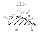
- a rubber extruded member 108 in which the unvulcanized side-wall rubber layer 106 and the unvulcanized rubber chafer 102 having the cross sectional configuration as shown in Fig. 8 are integrated with each other is produced. Thereafter, a rubber sheet 110 comprised of unvulcanized rubber of the same kind as the side-wall rubber layer 106 is adhered so as to cover a region of the rubber extruded member 108 in the vicinity of the end of the rubber chafer 102.
- the rubber extruded member 108 with the rubber sheet 110 adhered thereto is applied to an outer surface of a carcass of a tire case in a production process.
- the pneumatic tire is manufactured.
- a stepped portion 112 is formed on the surface of the rubber extruded member 108, as shown in Fig. 8. For this reason, air in the stepped portion 112 may cause bare. Moreover, losses due to spoiled products caused by incorrect setting may also increase.
- An object of the present invention is to provide a method and apparatus for extruding unvulcanized rubber, in which equipment investment for tires is held down, the number of manufacturing steps is not increased, and an unvulcanized rubber extruded member from which a high quality tire is produced can be formed by extrusion.
- a first aspect of the present invention is an apparatus for extruding unvulcanized rubber which comprises a first extruder main body for extruding a first unvulcanized rubber, a second extruder main body for extruding a second unvulcanized rubber, an extrusion head which connects a leading end of the first extruder main body and the second extruder main body, and a passage-forming die for guiding, at a leading end of the extrusion head, the first unvulcanized rubber and the second unvulcanized rubber toward a die plate having an opening, wherein an extruded rubber member is formed by extrusion, the extruded rubber member having a cross sectional configuration in which, when seen from a cross section perpendicular to a direction in which the extruded rubber member is extruded, a portion of the second unvulcanized rubber intrudes into the first unvulcanized rubber and a portion of the first unvulcanized rubber is disposed at both sides of the intruded second unvul
- the first unvulcanized rubber and the second unvulcanized rubber are each delivered to the passage-forming die by using the first extruder main body and the second extruder main body, respectively.
- the first unvulcanized rubber passes through the first passage formed in the passage-forming die and the second unvulcanized rubber passes through the second passage formed in the passage-forming die.
- the flow dividing mechanism provided between the first passage and the second passage divides a portion of the flowing first unvulcanized rubber passed through the first passage so that the first unvulcanized rubber is disposed in the extruded rubber member at both sides of the intruded second unvulcanized rubber in a direction intersecting a direction in which the second unvulcanized rubber intrudes.
- the extruded rubber member is readily obtained by one extrusion process, and the member has a cross sectional configuration in which, when seen in a cross section perpendicular to a direction in which the extruded rubber member is extruded, at a boundary portion between the first unvulcanized rubber and the second unvulcanized rubber, a portion of the second unvulcanized rubber intrudes into the first unvulcanized rubber, and a portion of the first unvulcanized rubber is disposed at both sides of the intruded second unvulcanized rubber in a direction intersecting a direction in which the second unvulcanized rubber intrudes.
- the flow dividing mechanism includes a first weir disposed at an upstream side of the die plate and apart from the die plate, and protruding from the second passage side toward the first passage in a direction perpendicular to a direction in which the unvulcanized rubbers pass.
- the weir formed so as to protrude from the second passage toward the first passage in a direction perpendicular to a direction in which unvulcanized rubber passes is provided at the upstream side of the die plate and apart from the die plate.
- the direction in which a portion of the first unvulcanized rubber passes through the first passage can be changed so that the portion of the first unvulcanized rubber rides over a protruding end of the weir, and the direction in which the other portion of the first unvulcanized rubber flows can be changed so that the other portion of the first unvulcanized rubber flows laterally around the weir in a direction perpendicular to a direction in which the weir protrudes.
- the portion of the first unvulcanized rubber is disposed at one side of the intruded second unvulcanized rubber in the direction in which the second unvulcanized rubber intrudes, and the other portion of the first unvulcanized rubber is disposed at another side of the intruded second unvulcanized rubber.
- a second aspect of the present invention is a method for extruding unvulcanized rubber, in which an extruded rubber member is formed by extrusion by an extruding apparatus, the extruded rubber member having a cross sectional configuration in which a portion of the second unvulcanized rubber intrudes into the first unvulcanized rubber and a portion of the first unvulcanized rubber is disposed at both sides of the intruded second unvulcanized rubber in a direction intersecting a direction in which the second unvulcanized rubber intrudes, the method comprising the steps of: dividing a portion of the flowing first unvulcanized rubber into two flows at an upstream side of a die plate including an opening in the extruding apparatus; allowing a portion of the second unvulcanized rubber to intrude in between the two flows into which the portion of the first unvulcanized rubber is divided; and extruding, from the opening of the die plate, an extruded rubber member in which the first unvulcanized rubber and the second unvulcan
- a portion of the flowing first unvulcanized rubber is divided into two parts at the upstream side of the die plate having the opening for the extruding apparatus, and a portion of the second unvulcanized rubber is caused to intrude in between the two divided flows of the first unvulcanized rubber. Thereafter, the first unvulcanized rubber and the second unvulcanized rubber are integrated with each other and an extruded rubber member having the first and second unvulcanized rubbers integrated is extruded from the opening of the die plate.
- the extruding apparatus includes a flow dividing mechanism including a first weir which is provided at the upstream side of the die plate and apart from the die plate and which protrudes in a direction perpendicular to a direction in which the first unvulcanized rubber passes, the first unvulcanized rubber and the second unvulcanized rubber are caused to intersect with each other by allowing the second unvulcanized rubber to pass over the first weir.
- the flow dividing mechanism includes a second weir extending from the first weir to the die plate, and the position of one of leading ends of two divided flows of the first unvulcanized rubber disposed at both sides of the second unvulcanized rubber is changed by the position of the second weir.
- the aforementioned method preferably, further comprises a step of: causing a portion of a third unvulcanized rubber to intrude into the first unvulcanized rubber, and an extruded rubber member having a region in which the first unvulcanized rubber and the third unvulcanized rubber are integrated with each other is extruded from the opening of the die plate.
- the unvulcanized rubber extruding apparatus 10 has three extruder main bodies 12, 14 and 16, and an extrusion head 18 to which ends of the extruder main bodies 12, 14 and 16 are connected.
- the extruder main bodies 12, 14 and 16 each include a hopper (not shown) for supplying unvulcanized rubber, and three kinds of unvulcanized rubbers A, B and C having different compositions are continuously supplied from the hoppers to the extruder main bodies 12, 14 and 16, respectively.
- the supplied unvulcanized rubbers A, B and C are each kneaded by screws (not shown) driven to rotate within the extruder main bodies 12, 14 or 16.
- the unvulcanized rubbers A, B and C are caused to flow toward the extrusion head 18 while exhibiting enhanced fluidity due to a self-exothermic property and increased plasticity.
- the extruder main bodies 12, 14 and 16 each have the same structure as in a conventional system.
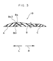
- an unvulcanized rubber member 19 is comprised of the three kinds of unvulcanized rubber, that is, the unvulcanized rubber A for forming a rubber chafer, the unvulcanized rubber B for forming a side-wall rubber layer, and the unvulcanized rubber C for a cushion rubber layer to be disposed at an inner side of a tread at a position near a tire shoulder.
- the unvulcanized rubber member 19 is formed by extrusion so as to become wide in a horizontal direction, that is, in the direction indicated by arrows L and R.
- a substantially V-shaped groove portion Ba is provided at an end of the unvulcanized rubber B (the side-wall rubber layer) in the direction indicated by arrow L.
- a lower portion of the groove portion Ba is formed as an inner portion Ba1 along an outer surface of a carcass of a product tire, and an upper portion of the groove portion Ba is formed as an outer portion Ba2 along an outer wall surface of the tire.
- the inner portion Ba1 and the outer portion Ba2 are each formed so as to be tapered with the thickness thereof being gradually decreased toward the end in the direction indicated by arrow L.
- the unvulcanized rubber A (rubber chafer) extends in the widthwise direction in the same manner as the unvulcanized rubber B (side-wall rubber layer), that is, in the direction indicated by arrows L and R, and is formed in a tapered manner so that the thickness thereof gradually decreases from a thick central portion to both ends in the widthwise direction.
- the end of the unvulcanized rubber A (rubber chafer) at the side of the unvulcanized rubber B (side-wall rubber layer) is covered such that the upper surface thereof is in contact with the outer portion Ba2 and the lower surface thereof is in contact with the inner portion Ba1.
- the other end of the unvulcanized rubber B (side-wall rubber layer) in the direction indicated by arrow R is formed in a tapered manner so that the thickness thereof gradually decreases toward the end.
- the vulcanized rubber C (cushion rubber layer) is disposed at the end of the unvulcanized rubber B (side-wall rubber layer) in the direction indicated by arrow R.
- the unvulcanized rubber C may not necessarily be required, depending on the type of tire.
- the unvulcanized rubber C (cushion rubber layer) is formed in a tapered manner so that the thickness thereof gradually decreases from the central portion to the both ends thereof in the widthwise direction. A portion of the unvulcanized rubber C in the direction indicated by arrow L is covered by the other end of the unvulcanized rubber B (side-wall rubber layer) from an upper side.
- the extrusion head 18 includes an extrusion die plate (hereinafter referred to as "die plate") 20 positioned at a front side in a direction in which the unvulcanized rubbers A, B and C are extruded, and also includes passages 22a, 22b and 22c for the unvulcanized rubbers A, B and C, which are directed toward the die plate 20 from extrusion orifices of the extruder main bodies 12, 14 and 16.
- die plate extrusion die plate
- the extrusion head 18 detachably accommodates an unvulcanized rubber member-forming device 24 for forming the unvulcanized rubber member 19, in which the unvulcanized rubbers A, B and C each have a predetermined cross sectional configuration, at a position between ends of the passages 22a, 22b and 22c and the front side of the die plate 20.
- the unvulcanized rubber member 19 is extruded from the die plate 20 in the direction indicated by arrow F in Fig. 4.
- the unvulcanized rubber member-forming device 24 has a back die 26 which serves to form a bottom portion of an outer contour of the die plate 20 to make a pair together with the die plate 20, a die holder 28 for holding and fixing the die plate 20 to the extrusion head 18, and a back die holder 30 for holding and fixing the back die 26 to the extrusion head 18.
- a passage-forming die 32 is provided between the ends of the passages 22a, 22b and 22c of the extrusion head 18 and the die plate 20.
- the passage-forming die 32 includes, at a central portion thereof, a passage 34b through which the unvulcanized rubber B flows, and also includes a passage 34a through which the unvulcanized rubber A flows, at a side in the direction indicated by arrow L, and a passage 34c through which the unvulcanized rubber C flows, at a side in the direction indicated by arrow R.
- the passage 34a and the passage 34b are connected to each other.
- the passage 34a has a stepped portion 36 at a side in the direction indicated by arrow U.
- a first weir 38 which serves as a flaw dividing mechanism, is provided at an end of the stepped portion 36 in the direction indicated by arrow D (that is, a portion at which the passage 34a and the passage 34b are connected) so as to protrude toward the passage 34b in the direction indicated by arrow D.
- the dimension of the first weir 38 protruding toward the passage 34b is gradually made shorter from a substantially intermediate portion thereof in the direction indicated by arrow L.
- An end 38a of the first weir 38 in the direction indicated by arrow D is disposed at a substantially intermediate position with respect to an opening portion 40 formed by the die plate 20 in a direction corresponding to thickness of the rubber extruded member. As shown in Fig. 6B, the end 38a of the first weir 38 extends to a position near an intermediate portion of the cross section of the passage 34b in a vertical direction of the die (that is, in the directions indicated by arrows U and D).
- a partition wall 42 is integrally formed with the end of the first weir 38 in the direction indicated by arrow R so as to protrude toward the passage 34b.
- the partition wall 42 is formed upright from the first weir 38 so as to reach the extrusion head 18 (in the direction indicated by arrow B).
- a second weir 44 is provided between the first weir 38 and the die plate 20 so as to protrude toward the passage 34b from a side surface 36b of the stepped portion 36 located at a side in the direction indicated by arrow F.
- the end of the second weir 44 reaches the opening portion of the die plate 20.
- the passage 22a of the extrusion head 18 is opened at a position which faces the stepped portion 36, and the passage 22b is opened at a central portion of the passage 34b in the widthwise direction.
- an opening of the passage 34c at the side of the die plate 20 is located in the vicinity of an end of the passage 22b at the side in the direction indicated by arrow R.
- the unvulcanized rubbers A, B and C are delivered by the extruder main bodies 12, 14 and 16, respectively, toward the extrusion head 18.
- the unvulcanized rubber A is fed into the passage 34a via the passage 22a
- the unvulcanized rubber B is fed into the passage 34b via the passage 22b
- the unvulcanized rubber C is fed into the passage 34c via the passage 22c.
- the unvulcanized rubber A flows toward the die plate 20 as indicated by arrows a1 and a2
- the unvulcanized rubber B flows toward the die plate 20 as indicated by arrows b1, b2, b3 and b4
- the unvulcanized rubber C flows toward the die plate 20 as indicated by arrows c1 and c2.
- the unvulcanized rubber A is pushed out from the die plate 20 at the side in the direction indicated by arrow L, and the vulcanized rubber C is pushed out from the die plate 20 at the side in the direction indicated by arrow R.
- the unvulcanized rubber B is pushed out from the central portion of the die plate 20.
- the flow of unvulcanized rubber A is partially changed by the first weir 38 in the direction indicated by arrow D so as to ride across the first weir 38 as shown by the arrow a2, and thereafter, the unvulcanized rubber A flows toward the die plate 20 in the direction indicated by arrow F.
- a portion of the unvulcanized rubber B flows in the direction indicated by arrow L as indicated by arrow b2 at the side of the direction indicated by arrow U (at the side of the stepped portion 36) in which the unvulcanized rubber A flows as indicated by arrow a2.
- a portion of the unvulcanized rubber B flows toward the die plate 20 in the direction of arrow F in such a manner as indicated by arrow b1.
- the end of the outer portion Ba2 of the unvulcanized rubber B can be changed by the position of the second weir 44 which changes the direction in which the unvulcanized rubber B flows as indicated by arrow b2 (in the directions indicated by arrows L and R).
- border line between the unvulcanized rubber A and the unvulcanized rubber B in the unvulcanized rubber member 19 can also be changed by extrusion pressure of each unvulcanized rubber.
- the use of the unvulcanized rubber extruding apparatus 10 of the present embodiment allows formation of the unvulcanized rubber member 19 shown in the cross section of Fig. 3 in one process. Further, unlike conventional, the unvulcanized rubber member 19 does not have a stepped portion formed by sticking a rubber sheet onto the surface thereof. Therefore, there is no possibility of bare occurring.
- the method and apparatus for extruding unvulcanized rubber according to the present invention has an excellent effect in that the number of processes for manufacturing tires is not increased and an unvulcanized rubber member from which a high quality tire can be obtained can be effectively produced.
Landscapes
- Engineering & Computer Science (AREA)
- Mechanical Engineering (AREA)
- Extrusion Moulding Of Plastics Or The Like (AREA)
Abstract
Description
- The present invention relates to a method and apparatus for extruding unvulcanized rubber, in which an unvulcanized rubber member comprised of at least two kinds of unvulcanized rubbers is extruded.
- In an automobile pneumatic tire, there are some cases in which a rubber chafer comprised of hard rubber may be provided at the outer side of a tire bead portion so as to increase rigidity of the bead portion.
- An upper end of the rubber chafer is connected to a side-wall rubber layer which forms a side wall of the tire.
- However, there are cases in which, because the bead portion is repeatedly subjected to bending deformation when the vehicle is running, the rubber chafer and the side-wall rubber layer are separated from each other.
- In order to solve the aforementioned problem, it has been considered that an area in which the rubber chafer and the side-wall rubber layer are connected can be increased, and a pneumatic tire having a cross sectional configuration as shown in Fig. 7 has been proposed.
- In the pneumatic tire having the cross sectional configuration shown in Fig. 7, an
inner portion 106A provided at a radial-direction inner side of a side-wall rubber layer 106 which forms aside wall 104, and anouter portion 106B provided at an outer side of the side-wall rubber layer 106 are formed so as to cover inner and outer surfaces, in an axial direction of the tire, of arubber chafer 102 tapered in an upward direction, and an area in which the side-wall rubber layer 106 and therubber chafer 102 are connected is increased so as to strengthen the junction between the side-wall rubber layer 106 and therubber chafer 102. - In order to manufacture such a pneumatic tire, in a process for producing a green tire, a rubber extruded
member 108 in which the unvulcanized side-wall rubber layer 106 and theunvulcanized rubber chafer 102 having the cross sectional configuration as shown in Fig. 8 are integrated with each other is produced. Thereafter, arubber sheet 110 comprised of unvulcanized rubber of the same kind as the side-wall rubber layer 106 is adhered so as to cover a region of the rubber extrudedmember 108 in the vicinity of the end of therubber chafer 102. - The rubber extruded
member 108 with therubber sheet 110 adhered thereto is applied to an outer surface of a carcass of a tire case in a production process. Thus, the pneumatic tire is manufactured. - However, there conventionally existed a problem that equipment for adhering the
rubber sheet 110 or a process for adhering the sheet may be required, and equipment investment and stock handling of therubber sheet 10 may also increase. - Further, because the
thick rubber sheet 110 is adhered to the rubber extrudedmember 108, astepped portion 112 is formed on the surface of the rubber extrudedmember 108, as shown in Fig. 8. For this reason, air in thestepped portion 112 may cause bare. Moreover, losses due to spoiled products caused by incorrect setting may also increase. - An object of the present invention is to provide a method and apparatus for extruding unvulcanized rubber, in which equipment investment for tires is held down, the number of manufacturing steps is not increased, and an unvulcanized rubber extruded member from which a high quality tire is produced can be formed by extrusion.
- A first aspect of the present invention is an apparatus for extruding unvulcanized rubber which comprises a first extruder main body for extruding a first unvulcanized rubber, a second extruder main body for extruding a second unvulcanized rubber, an extrusion head which connects a leading end of the first extruder main body and the second extruder main body, and a passage-forming die for guiding, at a leading end of the extrusion head, the first unvulcanized rubber and the second unvulcanized rubber toward a die plate having an opening, wherein an extruded rubber member is formed by extrusion, the extruded rubber member having a cross sectional configuration in which, when seen from a cross section perpendicular to a direction in which the extruded rubber member is extruded, a portion of the second unvulcanized rubber intrudes into the first unvulcanized rubber and a portion of the first unvulcanized rubber is disposed at both sides of the intruded second unvulcanized rubber in a direction intersecting a direction in which the second unvulcanized rubber intrudes, the apparatus comprising: a first passage through which the first unvulcanized rubber passes; a second passage provided adjacent to or connected to the first passage and making the second unvulcanized rubber to pass therethrough; and a flow dividing mechanism provided at one of a portion at which the first passage and the second passage are disposed adjacently and a portion at which these passages are connected, and separating a portion of the first unvulcanized rubber passing through the first passage to allow the first unvulcanized rubber to be disposed at both sides of the intruded second unvulcanized rubber in a direction intersecting a direction in which the second unvulcanized rubber intrudes.
- In the apparatus for extruding unvulcanized rubber, the first unvulcanized rubber and the second unvulcanized rubber are each delivered to the passage-forming die by using the first extruder main body and the second extruder main body, respectively.
- The first unvulcanized rubber passes through the first passage formed in the passage-forming die and the second unvulcanized rubber passes through the second passage formed in the passage-forming die.
- The flow dividing mechanism provided between the first passage and the second passage divides a portion of the flowing first unvulcanized rubber passed through the first passage so that the first unvulcanized rubber is disposed in the extruded rubber member at both sides of the intruded second unvulcanized rubber in a direction intersecting a direction in which the second unvulcanized rubber intrudes.
- As a result, the extruded rubber member is readily obtained by one extrusion process, and the member has a cross sectional configuration in which, when seen in a cross section perpendicular to a direction in which the extruded rubber member is extruded, at a boundary portion between the first unvulcanized rubber and the second unvulcanized rubber, a portion of the second unvulcanized rubber intrudes into the first unvulcanized rubber, and a portion of the first unvulcanized rubber is disposed at both sides of the intruded second unvulcanized rubber in a direction intersecting a direction in which the second unvulcanized rubber intrudes.
- In the apparatus for extruding unvulcanized rubber of the present invention, preferably, the flow dividing mechanism includes a first weir disposed at an upstream side of the die plate and apart from the die plate, and protruding from the second passage side toward the first passage in a direction perpendicular to a direction in which the unvulcanized rubbers pass.
- In the aforementioned apparatus for extruding unvulcanized rubber, the weir formed so as to protrude from the second passage toward the first passage in a direction perpendicular to a direction in which unvulcanized rubber passes is provided at the upstream side of the die plate and apart from the die plate. For this reason, the direction in which a portion of the first unvulcanized rubber passes through the first passage can be changed so that the portion of the first unvulcanized rubber rides over a protruding end of the weir, and the direction in which the other portion of the first unvulcanized rubber flows can be changed so that the other portion of the first unvulcanized rubber flows laterally around the weir in a direction perpendicular to a direction in which the weir protrudes.
- As a result, the portion of the first unvulcanized rubber is disposed at one side of the intruded second unvulcanized rubber in the direction in which the second unvulcanized rubber intrudes, and the other portion of the first unvulcanized rubber is disposed at another side of the intruded second unvulcanized rubber.
- A second aspect of the present invention is a method for extruding unvulcanized rubber, in which an extruded rubber member is formed by extrusion by an extruding apparatus, the extruded rubber member having a cross sectional configuration in which a portion of the second unvulcanized rubber intrudes into the first unvulcanized rubber and a portion of the first unvulcanized rubber is disposed at both sides of the intruded second unvulcanized rubber in a direction intersecting a direction in which the second unvulcanized rubber intrudes, the method comprising the steps of: dividing a portion of the flowing first unvulcanized rubber into two flows at an upstream side of a die plate including an opening in the extruding apparatus; allowing a portion of the second unvulcanized rubber to intrude in between the two flows into which the portion of the first unvulcanized rubber is divided; and extruding, from the opening of the die plate, an extruded rubber member in which the first unvulcanized rubber and the second unvulcanized rubber are integrated with each other.
- In the method for extruding unvulcanized rubber, a portion of the flowing first unvulcanized rubber is divided into two parts at the upstream side of the die plate having the opening for the extruding apparatus, and a portion of the second unvulcanized rubber is caused to intrude in between the two divided flows of the first unvulcanized rubber. Thereafter, the first unvulcanized rubber and the second unvulcanized rubber are integrated with each other and an extruded rubber member having the first and second unvulcanized rubbers integrated is extruded from the opening of the die plate.
- In the aforementioned method for extruding unvulcanized rubber of the present invention, preferably, the extruding apparatus includes a flow dividing mechanism including a first weir which is provided at the upstream side of the die plate and apart from the die plate and which protrudes in a direction perpendicular to a direction in which the first unvulcanized rubber passes, the first unvulcanized rubber and the second unvulcanized rubber are caused to intersect with each other by allowing the second unvulcanized rubber to pass over the first weir.
- Further, preferably, the flow dividing mechanism includes a second weir extending from the first weir to the die plate, and the position of one of leading ends of two divided flows of the first unvulcanized rubber disposed at both sides of the second unvulcanized rubber is changed by the position of the second weir.
- Moreover, the aforementioned method, preferably, further comprises a step of: causing a portion of a third unvulcanized rubber to intrude into the first unvulcanized rubber, and an extruded rubber member having a region in which the first unvulcanized rubber and the third unvulcanized rubber are integrated with each other is extruded from the opening of the die plate.
-
- Fig. 1A is a back view of a passage-forming die as seen from a side of extruders.
- Fig. 1B is a cross sectional view taken along the line 1(B) - 1(B) of the passage-forming die shown in Fig. 1A.
- Fig. 2 is a side view which schematically shows structure of an unvulcanized rubber extruding apparatus.
- Fig. 3 is a cross sectional view of an unvulcanized rubber member formed by extrusion by the unvulcanized rubber extruding apparatus.
- Fig. 4 is a longitudinal cross sectional view of an extrusion head.
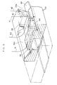
- Fig. 5 is a perspective view showing a portion of the passage-forming die.
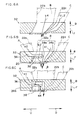
- Fig. 6A is a cross sectional view taken along the line 6(A) - 6(A) of the passage-forming die shown in Fig. 1A.
- Fig. 6B is a cross sectional view taken along the line 6(B) - 6(B) of the passage-forming die shown in Fig. 1A.
- Fig. 6C is a cross sectional view taken along the line 6(C) - 6(C) of the passage-forming die shown in Fig. 1A.
- Fig. 7 is a cross sectional view showing a bead portion of a conventional pneumatic tire.
- Fig. 8 is a cross sectional view of a conventional unvulcanized rubber member.
-
- An embodiment of an unvulcanized rubber extruding apparatus of the present invention will be described hereinafter with reference to Figs. 1 to 6.
- As shown in Fig. 2, the unvulcanized
rubber extruding apparatus 10 has three extrudermain bodies extrusion head 18 to which ends of the extrudermain bodies - The extruder
main bodies main bodies main bodies extrusion head 18 while exhibiting enhanced fluidity due to a self-exothermic property and increased plasticity. - The extruder
main bodies - Next, an
unvulcanized rubber member 19 formed by extrusion with the unvulcanizedrubber extruding apparatus 10 will be described with reference to Fig. 3. - As shown in the cross sectional view of Fig. 3, an
unvulcanized rubber member 19 is comprised of the three kinds of unvulcanized rubber, that is, the unvulcanized rubber A for forming a rubber chafer, the unvulcanized rubber B for forming a side-wall rubber layer, and the unvulcanized rubber C for a cushion rubber layer to be disposed at an inner side of a tread at a position near a tire shoulder. Theunvulcanized rubber member 19 is formed by extrusion so as to become wide in a horizontal direction, that is, in the direction indicated by arrows L and R. - In the
unvulcanized rubber member 19, a substantially V-shaped groove portion Ba is provided at an end of the unvulcanized rubber B (the side-wall rubber layer) in the direction indicated by arrow L. At the end of the unvulcanized rubber B, a lower portion of the groove portion Ba is formed as an inner portion Ba1 along an outer surface of a carcass of a product tire, and an upper portion of the groove portion Ba is formed as an outer portion Ba2 along an outer wall surface of the tire. - The inner portion Ba1 and the outer portion Ba2 are each formed so as to be tapered with the thickness thereof being gradually decreased toward the end in the direction indicated by arrow L.
- The unvulcanized rubber A (rubber chafer) extends in the widthwise direction in the same manner as the unvulcanized rubber B (side-wall rubber layer), that is, in the direction indicated by arrows L and R, and is formed in a tapered manner so that the thickness thereof gradually decreases from a thick central portion to both ends in the widthwise direction.
- The end of the unvulcanized rubber A (rubber chafer) at the side of the unvulcanized rubber B (side-wall rubber layer) is covered such that the upper surface thereof is in contact with the outer portion Ba2 and the lower surface thereof is in contact with the inner portion Ba1.
- The other end of the unvulcanized rubber B (side-wall rubber layer) in the direction indicated by arrow R is formed in a tapered manner so that the thickness thereof gradually decreases toward the end.
- The vulcanized rubber C (cushion rubber layer) is disposed at the end of the unvulcanized rubber B (side-wall rubber layer) in the direction indicated by arrow R. The unvulcanized rubber C may not necessarily be required, depending on the type of tire.
- The unvulcanized rubber C (cushion rubber layer) is formed in a tapered manner so that the thickness thereof gradually decreases from the central portion to the both ends thereof in the widthwise direction. A portion of the unvulcanized rubber C in the direction indicated by arrow L is covered by the other end of the unvulcanized rubber B (side-wall rubber layer) from an upper side.
- Next, the unvulcanized
rubber extruding apparatus 10 will be described in detail. - As shown in Fig. 4, the
extrusion head 18 includes an extrusion die plate (hereinafter referred to as "die plate") 20 positioned at a front side in a direction in which the unvulcanized rubbers A, B and C are extruded, and also includespassages die plate 20 from extrusion orifices of the extrudermain bodies extrusion head 18 detachably accommodates an unvulcanized rubber member-formingdevice 24 for forming theunvulcanized rubber member 19, in which the unvulcanized rubbers A, B and C each have a predetermined cross sectional configuration, at a position between ends of thepassages die plate 20. - The
unvulcanized rubber member 19 is extruded from thedie plate 20 in the direction indicated by arrow F in Fig. 4. - The unvulcanized rubber member-forming
device 24 has aback die 26 which serves to form a bottom portion of an outer contour of thedie plate 20 to make a pair together with thedie plate 20, adie holder 28 for holding and fixing thedie plate 20 to theextrusion head 18, and aback die holder 30 for holding and fixing the back die 26 to theextrusion head 18. - In the unvulcanized rubber member-forming
device 24, a passage-formingdie 32 is provided between the ends of thepassages extrusion head 18 and thedie plate 20. - As shown in Figs. 1A, 1B, 5, 6A, 6B and 6C, the passage-forming
die 32 includes, at a central portion thereof, apassage 34b through which the unvulcanized rubber B flows, and also includes apassage 34a through which the unvulcanized rubber A flows, at a side in the direction indicated by arrow L, and apassage 34c through which the unvulcanized rubber C flows, at a side in the direction indicated by arrow R. - The
passage 34a and thepassage 34b are connected to each other. - The
passage 34a has a steppedportion 36 at a side in the direction indicated by arrow U. - A
first weir 38, which serves as a flaw dividing mechanism, is provided at an end of the steppedportion 36 in the direction indicated by arrow D (that is, a portion at which thepassage 34a and thepassage 34b are connected) so as to protrude toward thepassage 34b in the direction indicated by arrow D. - As shown in Fig. 1A, the dimension of the
first weir 38 protruding toward thepassage 34b is gradually made shorter from a substantially intermediate portion thereof in the direction indicated by arrow L. - An
end 38a of thefirst weir 38 in the direction indicated by arrow D is disposed at a substantially intermediate position with respect to anopening portion 40 formed by thedie plate 20 in a direction corresponding to thickness of the rubber extruded member. As shown in Fig. 6B, theend 38a of thefirst weir 38 extends to a position near an intermediate portion of the cross section of thepassage 34b in a vertical direction of the die (that is, in the directions indicated by arrows U and D). - A
partition wall 42 is integrally formed with the end of thefirst weir 38 in the direction indicated by arrow R so as to protrude toward thepassage 34b. - The
partition wall 42 is formed upright from thefirst weir 38 so as to reach the extrusion head 18 (in the direction indicated by arrow B). - A
second weir 44 is provided between thefirst weir 38 and thedie plate 20 so as to protrude toward thepassage 34b from aside surface 36b of the steppedportion 36 located at a side in the direction indicated by arrow F. - The end of the
second weir 44 reaches the opening portion of thedie plate 20. - The
passage 22a of theextrusion head 18 is opened at a position which faces the steppedportion 36, and thepassage 22b is opened at a central portion of thepassage 34b in the widthwise direction. - Further, an opening of the
passage 34c at the side of thedie plate 20 is located in the vicinity of an end of thepassage 22b at the side in the direction indicated by arrow R. - Next, the operation of the unvulcanized
rubber extruding apparatus 10 will be described. - First, the unvulcanized rubbers A, B and C are delivered by the extruder
main bodies extrusion head 18. The unvulcanized rubber A is fed into thepassage 34a via thepassage 22a, the unvulcanized rubber B is fed into thepassage 34b via thepassage 22b, and the unvulcanized rubber C is fed into thepassage 34c via thepassage 22c. - In the passage-forming
die 32, the unvulcanized rubber A flows toward thedie plate 20 as indicated by arrows a1 and a2, the unvulcanized rubber B flows toward thedie plate 20 as indicated by arrows b1, b2, b3 and b4, and the unvulcanized rubber C flows toward thedie plate 20 as indicated by arrows c1 and c2. - As a result, the unvulcanized rubber A is pushed out from the
die plate 20 at the side in the direction indicated by arrow L, and the vulcanized rubber C is pushed out from thedie plate 20 at the side in the direction indicated by arrow R. The unvulcanized rubber B is pushed out from the central portion of thedie plate 20. - Specifically, the flow of unvulcanized rubber A is partially changed by the
first weir 38 in the direction indicated by arrow D so as to ride across thefirst weir 38 as shown by the arrow a2, and thereafter, the unvulcanized rubber A flows toward thedie plate 20 in the direction indicated by arrow F. - Further, as shown in Figs. 1A and 1B, at the
die plate 20 side of the first weir 38 (in the direction indicated by arrow F), a portion of the unvulcanized rubber B flows in the direction indicated by arrow L as indicated by arrow b2 at the side of the direction indicated by arrow U (at the side of the stepped portion 36) in which the unvulcanized rubber A flows as indicated by arrow a2. Moreover, at the side of the direction indicated by arrow D (at the side of theend 38a) in which the unvulcanized rubber A flows as indicated by arrow a2, a portion of the unvulcanized rubber B flows toward thedie plate 20 in the direction of arrow F in such a manner as indicated by arrow b1. - In other words, as shown by the cross sectional view of Fig. 3, in the
unvulcanized rubber member 19 formed by extrusion, the flow of the unvulcanized rubber B indicated by arrow b2 forms the outer portion Ba2, and the flow of the unvulcanized rubber B indicated by arrow b1 forms the inner portion Ba1. - The end of the outer portion Ba2 of the unvulcanized rubber B can be changed by the position of the
second weir 44 which changes the direction in which the unvulcanized rubber B flows as indicated by arrow b2 (in the directions indicated by arrows L and R). - Further, the border line between the unvulcanized rubber A and the unvulcanized rubber B in the
unvulcanized rubber member 19 can also be changed by extrusion pressure of each unvulcanized rubber. - Thus, the use of the unvulcanized
rubber extruding apparatus 10 of the present embodiment allows formation of theunvulcanized rubber member 19 shown in the cross section of Fig. 3 in one process. Further, unlike conventional, theunvulcanized rubber member 19 does not have a stepped portion formed by sticking a rubber sheet onto the surface thereof. Therefore, there is no possibility of bare occurring. - As described above, the method and apparatus for extruding unvulcanized rubber according to the present invention has an excellent effect in that the number of processes for manufacturing tires is not increased and an unvulcanized rubber member from which a high quality tire can be obtained can be effectively produced.
Claims (15)
- An apparatus for extruding unvulcanized rubber which comprises a first extruder main body for extruding a first unvulcanized rubber, a second extruder main body for extruding a second unvulcanized rubber, an extrusion head which connects a leading end of the first extruder main body and the second extruder main body, and a passage-forming die for guiding, at a leading end of the extrusion head, the first unvulcanized rubber and the second unvulcanized rubber toward a die plate having an opening, wherein an extruded rubber member is formed by extrusion, the extruded rubber member having a cross sectional configuration in which, when seen from a cross section perpendicular to a direction in which the extruded rubber member is extruded, a portion of the second unvulcanized rubber intrudes into the first unvulcanized rubber and a portion of the first unvulcanized rubber is disposed at both sides of the intruded second unvulcanized rubber in a direction intersecting a direction in which the second unvulcanized rubber intrudes, said apparatus comprising:a first passage through which the first unvulcanized rubber passes;a second passage provided adjacent to or connected to the first passage and making the second unvulcanized rubber to pass therethrough; anda flow dividing mechanism provided at one of a portion at which the first passage and the second passage are disposed adjacently and a portion at which these passages are connected, and separating a portion of the first unvulcanized rubber passing through the first passage to allow the first unvulcanized rubber to be disposed at both sides of the intruded second unvulcanized rubber in a direction intersecting a direction in which the second unvulcanized rubber intrudes.
- The apparatus of claim 1, wherein the flow dividing mechanism includes a first weir disposed at an upstream side of the die plate and apart from the die plate, and protruding from the second passage side toward the first passage in a direction perpendicular to a direction in which the unvulcanized rubbers pass.
- The apparatus of claim 2, wherein the first weir is substantially parallel to the die plate and includes a substantially trapezoidal shape.
- The apparatus of claim 2, wherein the flow dividing mechanism further comprises a partition wall extending substantially perpendicular from the first weir in a direction away from the die plate.
- The apparatus of claim 4, wherein one end portion of the first weir is connected to the passage-forming die and the other end portion thereof is disposed at a portion substantially corresponding to a widthwise intermediate portion of the opening of the die plate, the widthwise direction corresponding to a direction in which the first weir protrudes.
- The apparatus of claim 2, wherein the flow dividing mechanism further comprises a second weir which extends from the first weir toward the die plate.
- The apparatus of claim 6, wherein the second weir reaches the opening of the die plate.
- The apparatus of claim 6, further comprising:a third extruder main body, which extrudes a third type of unvulcanized rubber; anda third passage, through which the third unvulcanized rubber passes.
- The apparatus of claim 8, wherein the third passage is disposed adjacent to the first passage and at a side of the first passage opposite to a side at which the second passage is disposed.
- A method for extruding unvulcanized rubber, in which an extruded rubber member is formed by extrusion by an extruding apparatus, the extruded rubber member having a cross sectional configuration in which a portion of the second unvulcanized rubber intrudes into the first unvulcanized rubber and a portion of the first unvulcanized rubber is disposed at both sides of the intruded second unvulcanized rubber in a direction intersecting a direction in which the second unvulcanized rubber intrudes, said method comprising the steps of:dividing a portion of the flowing first unvulcanized rubber into two flows at an upstream side of a die plate including an opening in the extruding apparatus;allowing a portion of the second unvulcanized rubber to intrude in between the two flows into which the portion of the first unvulcanized rubber is divided; andextruding, from the opening of the die plate, an extruded rubber member in which the first unvulcanized rubber and the second unvulcanized rubber are integrated with each other.
- The method of claim 10, wherein the extruding apparatus includes a flow dividing mechanism including a first weir which is provided at the upstream side of the die plate and apart from the die plate and which protrudes in a direction perpendicular to a direction in which the first unvulcanized rubber passes, the first unvulcanized rubber and the second unvulcanized rubber are caused to intersect with each other by allowing the second unvulcanized rubber to pass over the first weir.
- The method of claim 11, wherein the flow dividing mechanism includes a second weir extending from the first weir to the die plate, and the position of one of leading ends of two divided flows of the first unvulcanized rubber disposed at both sides of the second unvulcanized rubber is changed by the position of the second weir.
- The method of claim 11, wherein a border line between the first unvulcanized rubber and the second unvulcanized rubber is changed by extrusion pressures of the first unvulcanized rubber and second unvulcanized rubber.
- The method of claim 11, further comprising a step of:causing a portion of a third unvulcanized rubber to intrude into the first unvulcanized rubber, and an extruded rubber member having a region in which the first unvulcanized rubber and the third unvulcanized rubber are integrated with each other is extruded from the opening of the die plate.
- The method of claim 14, wherein the third unvulcanized rubber intrudes into the first unvulcanized rubber at a side opposite to that at which the second unvulcanized rubber is disposed.
Applications Claiming Priority (2)
| Application Number | Priority Date | Filing Date | Title |
|---|---|---|---|
| JP2001069154A JP4611551B2 (en) | 2001-03-12 | 2001-03-12 | Unvulcanized rubber extrusion apparatus and unvulcanized rubber extrusion method |
| JP2001069154 | 2001-03-12 |
Publications (2)
| Publication Number | Publication Date |
|---|---|
| EP1240994A1 true EP1240994A1 (en) | 2002-09-18 |
| EP1240994B1 EP1240994B1 (en) | 2004-07-21 |
Family
ID=18927226
Family Applications (1)
| Application Number | Title | Priority Date | Filing Date |
|---|---|---|---|
| EP02251700A Expired - Lifetime EP1240994B1 (en) | 2001-03-12 | 2002-03-11 | Apparatus and method for extruding unvulcanized rubber |
Country Status (5)
| Country | Link |
|---|---|
| US (2) | US6875004B2 (en) |
| EP (1) | EP1240994B1 (en) |
| JP (1) | JP4611551B2 (en) |
| DE (1) | DE60200765T2 (en) |
| ES (1) | ES2224026T3 (en) |
Cited By (2)
| Publication number | Priority date | Publication date | Assignee | Title |
|---|---|---|---|---|
| ITTO20090965A1 (en) * | 2009-12-09 | 2011-06-10 | Bridgestone Corp | METHOD OF CONSTRUCTION OF A TIRE AND CORRESPONDING PNEUMATIC |
| EP2147770A4 (en) * | 2007-03-27 | 2012-12-05 | Bridgestone Corp | Unvulcanized rubber extruder and process for producing unvulcanized rubber |
Families Citing this family (7)
| Publication number | Priority date | Publication date | Assignee | Title |
|---|---|---|---|---|
| JP2009056652A (en) * | 2007-08-30 | 2009-03-19 | Bridgestone Corp | Method for molding pneumatic tire, and pneumatic tire |
| JP5566588B2 (en) * | 2008-01-29 | 2014-08-06 | 株式会社ブリヂストン | Unvulcanized rubber extruder |
| US8016580B2 (en) * | 2009-01-28 | 2011-09-13 | The Goodyear Tire & Rubber Company | Assembly and a method for extruding a tire component |
| JP5643209B2 (en) * | 2009-09-16 | 2014-12-17 | 株式会社ブリヂストン | Pneumatic radial tire |
| US20120160392A1 (en) * | 2010-12-22 | 2012-06-28 | Philip Carl Van Riper | Tire with optimized chafer |
| JP6536204B2 (en) * | 2015-06-18 | 2019-07-03 | 住友ゴム工業株式会社 | Method of manufacturing pneumatic tire |
| AU2023250926A1 (en) | 2022-04-05 | 2024-10-17 | Jd Russell Company | Device and method for making concrete expansion joint inserts |
Citations (7)
| Publication number | Priority date | Publication date | Assignee | Title |
|---|---|---|---|---|
| US4556376A (en) * | 1983-07-11 | 1985-12-03 | Continental Gummi-Werke Aktiengesellschaft | Extruder head for producing flat cohesive profiled webs from resilient mixtures of differing composition |
| US4653994A (en) * | 1985-06-15 | 1987-03-31 | Hermann Berstorff Maschinenbau Gmbh | Extrusion head for producing flat profiles from rubber or plastics material |
| DE3534734A1 (en) * | 1985-09-28 | 1987-04-09 | Krupp Gmbh | Method for operating a multi-extruder system |
| JPH04208443A (en) * | 1990-11-30 | 1992-07-30 | Bridgestone Corp | Pneumatic tire |
| JPH11240081A (en) * | 1997-12-26 | 1999-09-07 | Bridgestone Corp | Method for producing unvulcanized tread rubber for tire and pneumatic tire |
| JP2000117813A (en) * | 1998-10-16 | 2000-04-25 | Sumitomo Rubber Ind Ltd | Rubber extrusion equipment |
| JP2000351145A (en) * | 1999-06-11 | 2000-12-19 | Sumitomo Rubber Ind Ltd | Roller head rubber extrusion device |
Family Cites Families (9)
| Publication number | Priority date | Publication date | Assignee | Title |
|---|---|---|---|---|
| US3398431A (en) * | 1964-10-23 | 1968-08-27 | Nat Distillers And Chemicals C | Laminating extrusion die |
| US4731004A (en) * | 1984-10-12 | 1988-03-15 | Princeton Packaging, Inc. | Side-by-side co-extrusion of film using multiple materials |
| US4552521A (en) * | 1984-12-10 | 1985-11-12 | Gencorp Inc. | Apparatus for co-extruding a rubber strip of one material with a stripe of a second material |
| US4683095A (en) * | 1985-05-08 | 1987-07-28 | The Uniroyal Goodrich Tire Company | Early progressive junction extrusion process and system |
| JPH0794142B2 (en) * | 1990-07-03 | 1995-10-11 | 積水化学工業株式会社 | Apparatus for producing thermoplastic resin sheet and method for producing thermoplastic resin sheet using the same |
| JPH0811510A (en) * | 1994-06-29 | 1996-01-16 | Bridgestone Corp | Pneumatic radial tires for heavy loads |
| JP3880691B2 (en) * | 1997-07-08 | 2007-02-14 | 株式会社ブリヂストン | Pneumatic tire |
| US6294119B1 (en) * | 1997-12-26 | 2001-09-25 | Bridgestone Corporation | Production of unvulcanized tread rubber for pneumatic tires |
| ES2282373T3 (en) * | 2001-03-12 | 2007-10-16 | Bridgestone Corporation | TIRE. |
-
2001
- 2001-03-12 JP JP2001069154A patent/JP4611551B2/en not_active Expired - Fee Related
-
2002
- 2002-03-08 US US10/092,755 patent/US6875004B2/en not_active Expired - Lifetime
- 2002-03-11 ES ES02251700T patent/ES2224026T3/en not_active Expired - Lifetime
- 2002-03-11 DE DE2002600765 patent/DE60200765T2/en not_active Expired - Lifetime
- 2002-03-11 EP EP02251700A patent/EP1240994B1/en not_active Expired - Lifetime
-
2005
- 2005-01-24 US US11/039,839 patent/US7258827B2/en not_active Expired - Lifetime
Patent Citations (7)
| Publication number | Priority date | Publication date | Assignee | Title |
|---|---|---|---|---|
| US4556376A (en) * | 1983-07-11 | 1985-12-03 | Continental Gummi-Werke Aktiengesellschaft | Extruder head for producing flat cohesive profiled webs from resilient mixtures of differing composition |
| US4653994A (en) * | 1985-06-15 | 1987-03-31 | Hermann Berstorff Maschinenbau Gmbh | Extrusion head for producing flat profiles from rubber or plastics material |
| DE3534734A1 (en) * | 1985-09-28 | 1987-04-09 | Krupp Gmbh | Method for operating a multi-extruder system |
| JPH04208443A (en) * | 1990-11-30 | 1992-07-30 | Bridgestone Corp | Pneumatic tire |
| JPH11240081A (en) * | 1997-12-26 | 1999-09-07 | Bridgestone Corp | Method for producing unvulcanized tread rubber for tire and pneumatic tire |
| JP2000117813A (en) * | 1998-10-16 | 2000-04-25 | Sumitomo Rubber Ind Ltd | Rubber extrusion equipment |
| JP2000351145A (en) * | 1999-06-11 | 2000-12-19 | Sumitomo Rubber Ind Ltd | Roller head rubber extrusion device |
Non-Patent Citations (4)
| Title |
|---|
| PATENT ABSTRACTS OF JAPAN vol. 016, no. 549 (M - 1338) 18 November 1992 (1992-11-18) * |
| PATENT ABSTRACTS OF JAPAN vol. 1999, no. 14 22 December 1999 (1999-12-22) * |
| PATENT ABSTRACTS OF JAPAN vol. 2000, no. 07 29 September 2000 (2000-09-29) * |
| PATENT ABSTRACTS OF JAPAN vol. 2000, no. 15 6 April 2001 (2001-04-06) * |
Cited By (3)
| Publication number | Priority date | Publication date | Assignee | Title |
|---|---|---|---|---|
| EP2147770A4 (en) * | 2007-03-27 | 2012-12-05 | Bridgestone Corp | Unvulcanized rubber extruder and process for producing unvulcanized rubber |
| US8523551B2 (en) | 2007-03-27 | 2013-09-03 | Bridgestone Corporation | Unvulcanized rubber extruder and process for producing unvulcanized rubber |
| ITTO20090965A1 (en) * | 2009-12-09 | 2011-06-10 | Bridgestone Corp | METHOD OF CONSTRUCTION OF A TIRE AND CORRESPONDING PNEUMATIC |
Also Published As
| Publication number | Publication date |
|---|---|
| ES2224026T3 (en) | 2005-03-01 |
| JP2002264196A (en) | 2002-09-18 |
| DE60200765T2 (en) | 2005-01-13 |
| US7258827B2 (en) | 2007-08-21 |
| JP4611551B2 (en) | 2011-01-12 |
| EP1240994B1 (en) | 2004-07-21 |
| US6875004B2 (en) | 2005-04-05 |
| US20050121823A1 (en) | 2005-06-09 |
| DE60200765D1 (en) | 2004-08-26 |
| US20020125608A1 (en) | 2002-09-12 |
Similar Documents
| Publication | Publication Date | Title |
|---|---|---|
| JP5039127B2 (en) | Unvulcanized rubber extrusion apparatus and method for producing unvulcanized rubber | |
| US6495081B2 (en) | Method for manufacturing tread bands for vehicle tires | |
| CN1238176C (en) | Appts. for coextrusion of rubber mixtures | |
| EP0925903A1 (en) | Production of unvulcanized tread rubber for pneumatic tires | |
| US6875004B2 (en) | Apparatus for extruding unvulcanized rubber | |
| CN102029700A (en) | Multiple-preformer die of extrusion mold for tire treads | |
| NZ198168A (en) | Extrusion die throat contour | |
| JP2014180785A (en) | Apparatus and method for rubber molding | |
| CN100553935C (en) | Be used for to prevent the extrusion die of the tyre surface of tire static | |
| EP1207033B1 (en) | Method and device for producing a two-part tire layer | |
| KR102343891B1 (en) | Extrusion apparatus for manufacturing tire semi product | |
| JP2012081716A (en) | Rubber extruder | |
| JP2000318016A (en) | Rubber extrusion equipment | |
| JP5566588B2 (en) | Unvulcanized rubber extruder | |
| JP6587207B2 (en) | Tread, mold for tread molding, tread molding method, and green tire molding method | |
| CN114072275B (en) | Method for producing a pneumatic vehicle tire, device for shaping a rubber tread comprising two wings and a discharge, use of the device and pneumatic vehicle tire | |
| KR100558698B1 (en) | Extruder head mold structure for large tire tread | |
| KR100522091B1 (en) | Forming Roll for Bead & Apex ass´y | |
| KR20250062723A (en) | Extrusion die for manufacturing tire sidewall having multi-layers | |
| JP2001315187A (en) | Method for forming plastic polymer material and apparatus for forming plastic polymer material | |
| JP2021079645A (en) | Rubber extrusion molding apparatus | |
| JP2013141790A (en) | Inserter for extrusion molding | |
| JP2024001748A (en) | Extrusion head, rubber extrusion device, tread rubber manufacturing method, and tire manufacturing method | |
| JPH10166416A (en) | Die holder of head for multilayer extruder | |
| KR20180085431A (en) | Extrusion Apparatus for Capply |
Legal Events
| Date | Code | Title | Description |
|---|---|---|---|
| PUAI | Public reference made under article 153(3) epc to a published international application that has entered the european phase |
Free format text: ORIGINAL CODE: 0009012 |
|
| AK | Designated contracting states |
Kind code of ref document: A1 Designated state(s): AT BE CH CY DE DK ES FI FR GB GR IE IT LI LU MC NL PT SE TR |
|
| AX | Request for extension of the european patent |
Free format text: AL;LT;LV;MK;RO;SI |
|
| 17P | Request for examination filed |
Effective date: 20020913 |
|
| AKX | Designation fees paid |
Designated state(s): DE ES FR GB IT |
|
| GRAP | Despatch of communication of intention to grant a patent |
Free format text: ORIGINAL CODE: EPIDOSNIGR1 |
|
| RTI1 | Title (correction) |
Free format text: APPARATUS AND METHOD FOR EXTRUDING UNVULCANIZED RUBBER |
|
| GRAS | Grant fee paid |
Free format text: ORIGINAL CODE: EPIDOSNIGR3 |
|
| GRAA | (expected) grant |
Free format text: ORIGINAL CODE: 0009210 |
|
| AK | Designated contracting states |
Kind code of ref document: B1 Designated state(s): DE ES FR GB IT |
|
| REG | Reference to a national code |
Ref country code: GB Ref legal event code: FG4D |
|
| REF | Corresponds to: |
Ref document number: 60200765 Country of ref document: DE Date of ref document: 20040826 Kind code of ref document: P |
|
| ET | Fr: translation filed | ||
| REG | Reference to a national code |
Ref country code: ES Ref legal event code: FG2A Ref document number: 2224026 Country of ref document: ES Kind code of ref document: T3 |
|
| PLBE | No opposition filed within time limit |
Free format text: ORIGINAL CODE: 0009261 |
|
| STAA | Information on the status of an ep patent application or granted ep patent |
Free format text: STATUS: NO OPPOSITION FILED WITHIN TIME LIMIT |
|
| 26N | No opposition filed |
Effective date: 20050422 |
|
| REG | Reference to a national code |
Ref country code: DE Ref legal event code: R082 Ref document number: 60200765 Country of ref document: DE Representative=s name: HOFFMANN - EITLE, DE |
|
| REG | Reference to a national code |
Ref country code: FR Ref legal event code: CA Effective date: 20140812 |
|
| REG | Reference to a national code |
Ref country code: DE Ref legal event code: R082 Ref document number: 60200765 Country of ref document: DE Representative=s name: HOFFMANN - EITLE PATENT- UND RECHTSANWAELTE PA, DE Effective date: 20140828 Ref country code: DE Ref legal event code: R082 Ref document number: 60200765 Country of ref document: DE Representative=s name: HOFFMANN - EITLE, DE Effective date: 20140828 Ref country code: DE Ref legal event code: R081 Ref document number: 60200765 Country of ref document: DE Owner name: BRIDGESTONE CORPORATION, JP Free format text: FORMER OWNER: BRIDGESTONE CORP., TOKIO/TOKYO, JP Effective date: 20140828 |
|
| REG | Reference to a national code |
Ref country code: FR Ref legal event code: PLFP Year of fee payment: 15 |
|
| PGFP | Annual fee paid to national office [announced via postgrant information from national office to epo] |
Ref country code: ES Payment date: 20160309 Year of fee payment: 15 |
|
| PGFP | Annual fee paid to national office [announced via postgrant information from national office to epo] |
Ref country code: GB Payment date: 20160321 Year of fee payment: 15 |
|
| PGFP | Annual fee paid to national office [announced via postgrant information from national office to epo] |
Ref country code: IT Payment date: 20160324 Year of fee payment: 15 |
|
| REG | Reference to a national code |
Ref country code: FR Ref legal event code: PLFP Year of fee payment: 16 |
|
| GBPC | Gb: european patent ceased through non-payment of renewal fee |
Effective date: 20170311 |
|
| PG25 | Lapsed in a contracting state [announced via postgrant information from national office to epo] |
Ref country code: IT Free format text: LAPSE BECAUSE OF NON-PAYMENT OF DUE FEES Effective date: 20170311 Ref country code: GB Free format text: LAPSE BECAUSE OF NON-PAYMENT OF DUE FEES Effective date: 20170311 |
|
| REG | Reference to a national code |
Ref country code: FR Ref legal event code: PLFP Year of fee payment: 17 |
|
| REG | Reference to a national code |
Ref country code: ES Ref legal event code: FD2A Effective date: 20180703 |
|
| PG25 | Lapsed in a contracting state [announced via postgrant information from national office to epo] |
Ref country code: ES Free format text: LAPSE BECAUSE OF NON-PAYMENT OF DUE FEES Effective date: 20170312 |
|
| REG | Reference to a national code |
Ref country code: DE Ref legal event code: R079 Ref document number: 60200765 Country of ref document: DE Free format text: PREVIOUS MAIN CLASS: B29C0047560000 Ipc: B29C0048490000 |
|
| PGFP | Annual fee paid to national office [announced via postgrant information from national office to epo] |
Ref country code: DE Payment date: 20200320 Year of fee payment: 19 |
|
| PGFP | Annual fee paid to national office [announced via postgrant information from national office to epo] |
Ref country code: FR Payment date: 20200319 Year of fee payment: 19 |
|
| REG | Reference to a national code |
Ref country code: DE Ref legal event code: R119 Ref document number: 60200765 Country of ref document: DE |
|
| PG25 | Lapsed in a contracting state [announced via postgrant information from national office to epo] |
Ref country code: DE Free format text: LAPSE BECAUSE OF NON-PAYMENT OF DUE FEES Effective date: 20211001 Ref country code: FR Free format text: LAPSE BECAUSE OF NON-PAYMENT OF DUE FEES Effective date: 20210331 |