EP1239215A2 - Leuchtkörper zur Beleuchtung von Räumen - Google Patents
Leuchtkörper zur Beleuchtung von Räumen Download PDFInfo
- Publication number
- EP1239215A2 EP1239215A2 EP02005485A EP02005485A EP1239215A2 EP 1239215 A2 EP1239215 A2 EP 1239215A2 EP 02005485 A EP02005485 A EP 02005485A EP 02005485 A EP02005485 A EP 02005485A EP 1239215 A2 EP1239215 A2 EP 1239215A2
- Authority
- EP
- European Patent Office
- Prior art keywords
- light
- hollow body
- wall
- scattering
- luminous body
- Prior art date
- Legal status (The legal status is an assumption and is not a legal conclusion. Google has not performed a legal analysis and makes no representation as to the accuracy of the status listed.)
- Granted
Links
- 238000000149 argon plasma sintering Methods 0.000 claims abstract description 25
- 239000000463 material Substances 0.000 claims description 5
- 238000007688 edging Methods 0.000 claims description 3
- 230000000149 penetrating effect Effects 0.000 abstract 1
- 230000000694 effects Effects 0.000 description 14
- 238000009826 distribution Methods 0.000 description 13
- 230000003595 spectral effect Effects 0.000 description 9
- 238000005286 illumination Methods 0.000 description 8
- 230000005855 radiation Effects 0.000 description 5
- 230000002349 favourable effect Effects 0.000 description 4
- 238000002310 reflectometry Methods 0.000 description 4
- 238000010521 absorption reaction Methods 0.000 description 3
- 230000008901 benefit Effects 0.000 description 3
- 230000004907 flux Effects 0.000 description 3
- 239000011888 foil Substances 0.000 description 3
- 230000003287 optical effect Effects 0.000 description 3
- 230000005540 biological transmission Effects 0.000 description 2
- 239000003086 colorant Substances 0.000 description 2
- 238000005516 engineering process Methods 0.000 description 2
- 238000010438 heat treatment Methods 0.000 description 2
- QSHDDOUJBYECFT-UHFFFAOYSA-N mercury Chemical compound [Hg] QSHDDOUJBYECFT-UHFFFAOYSA-N 0.000 description 2
- 229920001343 polytetrafluoroethylene Polymers 0.000 description 2
- 239000004810 polytetrafluoroethylene Substances 0.000 description 2
- 238000004026 adhesive bonding Methods 0.000 description 1
- 230000002411 adverse Effects 0.000 description 1
- 238000013459 approach Methods 0.000 description 1
- 230000009286 beneficial effect Effects 0.000 description 1
- 230000015572 biosynthetic process Effects 0.000 description 1
- 238000000576 coating method Methods 0.000 description 1
- 238000001816 cooling Methods 0.000 description 1
- 230000004313 glare Effects 0.000 description 1
- 238000005304 joining Methods 0.000 description 1
- 238000004519 manufacturing process Methods 0.000 description 1
- 229910052753 mercury Inorganic materials 0.000 description 1
- 239000000203 mixture Substances 0.000 description 1
- 239000013307 optical fiber Substances 0.000 description 1
- 239000004033 plastic Substances 0.000 description 1
- 229920003023 plastic Polymers 0.000 description 1
- 239000011112 polyethylene naphthalate Substances 0.000 description 1
- -1 polytetrafluoroethylene Polymers 0.000 description 1
- 238000005096 rolling process Methods 0.000 description 1
- 239000004065 semiconductor Substances 0.000 description 1
- 238000001228 spectrum Methods 0.000 description 1
- 238000002834 transmittance Methods 0.000 description 1
Images


Classifications
-
- F—MECHANICAL ENGINEERING; LIGHTING; HEATING; WEAPONS; BLASTING
- F21—LIGHTING
- F21V—FUNCTIONAL FEATURES OR DETAILS OF LIGHTING DEVICES OR SYSTEMS THEREOF; STRUCTURAL COMBINATIONS OF LIGHTING DEVICES WITH OTHER ARTICLES, NOT OTHERWISE PROVIDED FOR
- F21V7/00—Reflectors for light sources
- F21V7/22—Reflectors for light sources characterised by materials, surface treatments or coatings, e.g. dichroic reflectors
-
- F—MECHANICAL ENGINEERING; LIGHTING; HEATING; WEAPONS; BLASTING
- F21—LIGHTING
- F21S—NON-PORTABLE LIGHTING DEVICES; SYSTEMS THEREOF; VEHICLE LIGHTING DEVICES SPECIALLY ADAPTED FOR VEHICLE EXTERIORS
- F21S11/00—Non-electric lighting devices or systems using daylight
-
- F—MECHANICAL ENGINEERING; LIGHTING; HEATING; WEAPONS; BLASTING
- F21—LIGHTING
- F21S—NON-PORTABLE LIGHTING DEVICES; SYSTEMS THEREOF; VEHICLE LIGHTING DEVICES SPECIALLY ADAPTED FOR VEHICLE EXTERIORS
- F21S19/00—Lighting devices or systems employing combinations of electric and non-electric light sources; Replacing or exchanging electric light sources with non-electric light sources or vice versa
-
- F—MECHANICAL ENGINEERING; LIGHTING; HEATING; WEAPONS; BLASTING
- F21—LIGHTING
- F21V—FUNCTIONAL FEATURES OR DETAILS OF LIGHTING DEVICES OR SYSTEMS THEREOF; STRUCTURAL COMBINATIONS OF LIGHTING DEVICES WITH OTHER ARTICLES, NOT OTHERWISE PROVIDED FOR
- F21V7/00—Reflectors for light sources
- F21V7/0008—Reflectors for light sources providing for indirect lighting
-
- F—MECHANICAL ENGINEERING; LIGHTING; HEATING; WEAPONS; BLASTING
- F21—LIGHTING
- F21S—NON-PORTABLE LIGHTING DEVICES; SYSTEMS THEREOF; VEHICLE LIGHTING DEVICES SPECIALLY ADAPTED FOR VEHICLE EXTERIORS
- F21S8/00—Lighting devices intended for fixed installation
- F21S8/04—Lighting devices intended for fixed installation intended only for mounting on a ceiling or the like overhead structures
-
- F—MECHANICAL ENGINEERING; LIGHTING; HEATING; WEAPONS; BLASTING
- F21—LIGHTING
- F21V—FUNCTIONAL FEATURES OR DETAILS OF LIGHTING DEVICES OR SYSTEMS THEREOF; STRUCTURAL COMBINATIONS OF LIGHTING DEVICES WITH OTHER ARTICLES, NOT OTHERWISE PROVIDED FOR
- F21V13/00—Producing particular characteristics or distribution of the light emitted by means of a combination of elements specified in two or more of main groups F21V1/00 - F21V11/00
- F21V13/02—Combinations of only two kinds of elements
- F21V13/04—Combinations of only two kinds of elements the elements being reflectors and refractors
-
- F—MECHANICAL ENGINEERING; LIGHTING; HEATING; WEAPONS; BLASTING
- F21—LIGHTING
- F21W—INDEXING SCHEME ASSOCIATED WITH SUBCLASSES F21K, F21L, F21S and F21V, RELATING TO USES OR APPLICATIONS OF LIGHTING DEVICES OR SYSTEMS
- F21W2131/00—Use or application of lighting devices or systems not provided for in codes F21W2102/00-F21W2121/00
- F21W2131/40—Lighting for industrial, commercial, recreational or military use
- F21W2131/402—Lighting for industrial, commercial, recreational or military use for working places
-
- F—MECHANICAL ENGINEERING; LIGHTING; HEATING; WEAPONS; BLASTING
- F21—LIGHTING
- F21Y—INDEXING SCHEME ASSOCIATED WITH SUBCLASSES F21K, F21L, F21S and F21V, RELATING TO THE FORM OR THE KIND OF THE LIGHT SOURCES OR OF THE COLOUR OF THE LIGHT EMITTED
- F21Y2103/00—Elongate light sources, e.g. fluorescent tubes
- F21Y2103/30—Elongate light sources, e.g. fluorescent tubes curved
- F21Y2103/33—Elongate light sources, e.g. fluorescent tubes curved annular
-
- F—MECHANICAL ENGINEERING; LIGHTING; HEATING; WEAPONS; BLASTING
- F21—LIGHTING
- F21Y—INDEXING SCHEME ASSOCIATED WITH SUBCLASSES F21K, F21L, F21S and F21V, RELATING TO THE FORM OR THE KIND OF THE LIGHT SOURCES OR OF THE COLOUR OF THE LIGHT EMITTED
- F21Y2113/00—Combination of light sources
- F21Y2113/10—Combination of light sources of different colours
- F21Y2113/13—Combination of light sources of different colours comprising an assembly of point-like light sources
-
- F—MECHANICAL ENGINEERING; LIGHTING; HEATING; WEAPONS; BLASTING
- F21—LIGHTING
- F21Y—INDEXING SCHEME ASSOCIATED WITH SUBCLASSES F21K, F21L, F21S and F21V, RELATING TO THE FORM OR THE KIND OF THE LIGHT SOURCES OR OF THE COLOUR OF THE LIGHT EMITTED
- F21Y2115/00—Light-generating elements of semiconductor light sources
- F21Y2115/10—Light-emitting diodes [LED]
Definitions
- the present invention relates to a luminous element for illuminating rooms with a hollow body bounded by a wall, which is used for multiple reflection of light inside is provided with reflective inner surfaces.
- Luminous elements for illuminating rooms are in one in the state of the art great variety and known in a wide variety of forms.
- the different Characteristics of light fixtures depend on the type of use. Here one can generally distinguish between luminous bodies, which the punctual Illuminate a specific area. For this genus of lights are as Example a reading lamp or a spotlight for illuminating stages in To lead theaters or the like.
- Another type of light fixture is used the illumination of rooms as evenly as possible.
- ceiling washlights, arrangement of fluorescent tubes etc. are often used.
- the Task of selective illumination of certain limited areas as well as that of evenly illuminating rooms often occurs simultaneously closed rooms. In the prior art, this often has to be solved Different types of lamps used in combination become.
- the task set is also determined by the Combination of different types of lights not completely solved.
- Common Problems are further that undesirable with different types of lights Color effects due to a restricted spectrum of the emitted light are caused.
- a mercury vapor lamp through the one in the Light source present "mercury sump" down through brown light down, while the portion of the light emitted that is not the swamp must penetrate, has a blue color.
- the object of the invention is therefore to create a generic luminous element, in which the disadvantages mentioned above are eliminated.
- the inner surfaces of the hollow body have a reflectance of at least 90% and are light-scattering are and in the wall of the hollow body at least one the wall Breakthrough light exit opening is provided.
- the luminous element has a wall of the hollow body has a light outlet opening.
- This targeted Light decoupling can be used for concentrated lighting of limited areas, however can also be used for the targeted illumination of rooms.
- This will overall a significantly improved illumination than with that in the prior art Known hollow body lights achieved, because this only the light via semi-transparent Submit areas.
- the use of light exit openings according to the invention is only possible with a sufficiently high luminance inside the filament. The high luminance and thus economical operation of such lights a correspondingly high luminaire operating efficiency is only possible through the reflectance according to the invention of the inner surfaces of the hollow body of at least 90% possible.
- the light-scattering design of the inner surfaces of the hollow body is also achieved on the one hand that light sources or other components not be shown to the outside within the hollow body.
- the light-scattering effect of the inner surfaces results in that of the filament only pleasantly diffusely scattered light is emitted.
- Scattering light here not only a perfect direction-independent ideal spread but in generally refers to an expansion of the reflected light beam.
- Overall is the light-scattering effect according to the invention characterized in that the Luminous light leaving no longer has preferred directions. This can, as stated below, can be achieved through various measures.
- the effective reflectance of the inner surfaces is determined by it diminishes. This leads to a reduction in the luminance inside the Luminous body or the hollow body. It is therefore favorable that the ratio of the Inner surface of the wall of the hollow body to the sum of all surfaces of all openings, preferably all light exit openings, larger than in the wall of the hollow body 5: 1, preferably greater than 10: 1.
- a ratio of the area of the wall of the hollow body to Sum of all areas of all openings in the wall of the hollow body greater than 20: 1 or greater than 30: 1 or preferably even greater than 40: 1.
- a luminous element can only be operated sensibly if its efficiency Eta is above a certain minimum value.
- the efficiency Eta depends on the inner surface of the wall, the sum of all surfaces of all openings and on the reflectance of the inner surfaces.
- the efficiency Eta is generally defined as the ratio of the luminous flux that exits the hollow body through A1 to the luminous flux of the supplying light sources. It is practical to provide in many embodiments of luminous bodies that the area of the light exit opening (s) is kept as small as possible, since this simplifies further light control of the light flux emitted through the light exit openings by appropriate optics. This is the case, for example, if further light-directing reflectors are to be used. From the formula given above for the efficiency Eta, it follows, for example, that if an efficiency of 65% is to be achieved with the good reflectivities of approximately 85% known in the prior art, the area ratio f should be more than 32%.
- the area ratio f has a value of 9.7%, which in turn means that the area of the light exit openings can be kept considerably smaller thanks to the high reflectance without loss of efficiency in Purchase would have to be taken. With correspondingly higher degrees of reflection, correspondingly smaller light exit openings can be used with constant efficiency.
- a preferred embodiment of the luminous element according to the invention provides that in the filament at least one light inlet opening preferably to the inlet of daylight and / or sunlight and / or at least one artificial light source is arranged.
- the hollow body with a diffusely reflecting inner surface can also be a or have several light entry opening (s) to alternatively or additionally to one integrated light source natural or artificial light from the outside through the Feed openings into the hollow body. Due to the multiple reflection of the light the inner surfaces of the hollow body is the position of the light inlet opening or Artificial light source in the hollow body of the filament regardless of the Luminous element total emitted luminous effect. This enables a very large one Freedom in the design of the shape of the light body.
- the light distribution emerging from the light exit opening is always diffusely scattered and regardless of the light distribution of the light source located in the hollow body and regardless of the light distribution of those flowing in through the inlet opening Is light source.
- the proportion can be controlled accordingly artificial light an almost uniform intensity of that of the filament emitted light with the maximum possible proportion of sunlight over the entire Daily routine can be maintained indoors.
- a preferred embodiment provides that two or more in the filament Light sources or light inlet openings, preferably for the admission of daylight and / or sunlight are arranged, the multiple reflection at the highly reflective inner surfaces the light introduced into the hollow body, preferably practically completely, mixes. This is how light in different colors becomes, whether it is now from one or different light sources in the hollow body of the Luminous body is irradiated in the manner by multiple reflections of the light the inner surfaces of the hollow body mixed so that it is always the light exit surfaces Mixed light, preferably white light, leaves. So daylight with artificial light or different colored light from different light sources in the hollow body of the Luminous body can be mixed specifically.
- the luminous element Due to the light mixing effect of the luminous element according to the invention, it can also be designed such that at least one light source is provided, which in different spatial directions different colored light with different Spectral distribution emits, whereby the multiple reflection of the light at the highly reflective inner surface of the hollow body the light of different spectral Light distribution or color distribution - preferably to white light - mixes.
- two or more light sources are provided are the light with different spectral light distribution or different Radiate color content, whereby the multiple reflection of light at the highly reflective inner surface of the hollow body the light of different spectral Distribution - preferably to white light - mixes.
- an embodiment of the Luminous body can also be used, the directional dependence of the intensity of light, which is caused by the emission characteristics of a light source, to eliminate.
- a preferred embodiment provides that at least one Light source is provided which has light in different spatial directions emits different intensities, whereby the multiple reflection of the light at the highly reflective inner surface of the hollow body causes the intensity of the from the luminous element - preferably via at least one light exit opening - emitted light is completely independent of direction.
- the leveling of the intensity achieved by the multiple reflection, the direction and the color content of the light emitted by the light source Light is especially for the use of different colored dots and linear light sources or different colored high pressure discharge lamps Cheap.
- the leveling effect can also be achieved when using several semiconductor light sources (e.g. LEDs) can be used.
- the highly reflective properties of the inner surface of the invention Hollow bodies can, as already mentioned above, by various measures can be achieved.
- a preferred variant provides that the light-scattering highly reflective inner surfaces, at least in some areas, preferably completely, have a light-scattering, preferably white, film.
- a white film can e.g. made of polytetrafluoroethylene (PTFE).
- PTFE polytetrafluoroethylene
- the light-scattering, highly reflective inner surfaces at least in some areas, preferably complete, a light scattering roughened, matted or etched Have surface.
- the light-scattering highly reflective inner surfaces at least partially completely preferably one - preferably made of knobs, Multiple edging, creasing or other straight or crooked bumps-light-scattering macroscopic surface structure.
- the macroscopic surface structure of shiny or high-gloss material.
- a high-gloss film or a high-gloss reflector plate the surface of which nubbed, grooved, multiple edged or the like is used. In this way, too, can reflectivities of the inner surfaces of the hollow body greater than 95% or 98% can be achieved. All these different variants of the Formation of the highly reflective light-scattering inner surfaces is, however together, that ultimately the lamp through the light exit opening leaving light is pleasantly diffused.
- a particularly preferred embodiment provides that at least one light-directing, preferably parabolically shaped, mirror optics or another Light guiding device arranged in the region of the light exit opening of the luminous element is and the emerging light limited angularly.
- panels can also be used be provided inside the hollow body, these diaphragms providing a direct view prevent the light source or the light inlet opening in the hollow body.
- a preferred embodiment of the luminous element according to the invention provides that it has a preferably diffusely scattering, for the non-reflected light component in the has substantially translucent wall. This makes one special uniform and pleasant illumination of a room. Through the through the high reflectance generated, highly concentrated luminance within the The very small cavity of the filament does not reach the inner surface of the Hollow body reflected but diffusely scattered transmitted through the wall Light component for uniform lighting that is pleasant for the human eye of a room. Through the transmission of the non-reflecting residual light the wall thus increases the efficiency of the filament, since almost all the light, however injected, leaves the filament as useful light.
- the wall or the luminous element contains as little light energy as possible Form of heat absorbed. This is especially true for those outside of the visible Range lying spectral ranges of the light, in particular for the infrared Wavelength range.
- the low heat absorption can be achieved by a high transmittance. Above all, there is good transmission of the infrared wavelength ranges of light in the foreground. So is the use of interior surfaces with a reflectance of at least 90% for visible ones Light components and a degree of reflection of only approx. 20% for the infrared range very cheap.
- cooling fins or the like can also be used Hollow body may be provided. Another one looks to prevent burns Variant of thermal contact protection e.g. in the form of grids, plastic ribs or the like.
- a preferred embodiment provides that the filament preferably cuboid hollow body, which with a highly reflective film is lined, wherein at least one lamp or at least in the hollow body a light entry opening, - preferably for daylight and / or sunlight - and at least one diaphragm is arranged, the direct radiation component being masked out is. This makes dazzling people otherwise very pleasant targeted light distribution prevented.
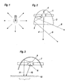
- Fig. 1 shows a simple light bulb, in the direction of the socket of the light bulb none Light is emitted.
- This is a schematic example of light sources in usually a directional dependence in the emitted intensity of the light exhibit. In Fig. 2, this is based on a located in a filament 2
- Light source 1 clarifies.
- the light source 1 in Fig. 2 emits in different Directions light with different intensity. This ultimately results in that in the angular range perpendicularly under the light source 1 or the light exit opening 3 of the Luminous body 2 light is emitted with a relatively high intensity.
- This is illustrated schematically by the light beam 4.
- the Intensity of the emitted light with increasing angle against the through Beam 4 shows the vertical direction of radiation. This will increase the light intensity the sides less. This laterally emitted light of lower intensity exemplified by rays 5 and 6.
- FIG. 3 a schematic representation of a filament with a discharge lamp shown.
- a lamp sump 9 forms on the bottom of a discharge lamp 8 changes the spectral content (color) of the light passing through it.
- the light generated by the gas discharge lamp is passed through the Filtered lamp sump 9 such that it is the gas discharge lamp as a brown light leaves towards the bottom.
- Beam 10 shown in Fig. 3.
- the beam path 11 does not lead through the lamp sump and the light running on its way is therefore not filtered through the lamp sump. It leaves on its way through a reflection on Reflector 7 the gas discharge lamp as blue light.
- the overall lighting effect of one Such a luminous element is thus characterized in that 12 Annoying color spots exist, since the plane of use 12 also has areas different colored light is illuminated.
- the Light emitted by the light source 13 becomes highly reflective on the light-scattering trained inner surface 14 of the hollow body 15 reflected several times before a part of light through the light exit opening 16 leaves the filament.
- the light-scattering highly reflective properties of the inner surfaces 14 can in all Embodiments e.g. through suitable coats, macroscopic Surface structures or the gluing of suitable foils can be achieved.
- Such foils can e.g. from polytetraethylene foils or from multilayer polymeric films with an outer layer of polyethylene naphthalate (PEN) be formed.
- the aperture 18 prevents that light directly from the lamp 13 through the light exit opening 16 Can leave filament. This prevents a person from directly light emitted by the light source is dazzled. That through the Light exit opening 16 is the light leaving the filament before leaving the Luminous body multiple light scattering on the highly reflective inner surface 14 has been reflected and is therefore a completely directional, spectral completely mixed, pleasant diffuse light.
- the Space through the light exit opening 16 can also diffuse light from the filament through the wall of the hollow body 15 when the wall of the Hollow body 15 is designed to be translucent. It should be noted that despite the high reflectance of the inner surface 14 of the hollow body 15 one for the Illumination of a room sufficient amount of light by the highly reflective Inner surface and the wall of the hollow body 15 can be transmitted since one with a suitable wall whose absorption is negligible and others due to the multiple reflection such a high luminance in the interior 19 of the hollow body is generated that the small percentage of the transmitted Low light is still sufficient to pleasantly illuminate rooms.
- the Ratio between that emerging through the wall 15 of the filament Light and the amount of light emerging through the light exit opening 16 essentially by the ratio of the area of the light exit opening 16 and the total area of the highly reflective inner wall 14 of the hollow body 15 determined and can be adapted to the respective need. So it's one precise control between the proportions of general room lighting with pleasant diffuse light and the concentrated illumination of limited areas possible.
- a corresponding design of the luminous element according to the invention can limit glare in all spatial directions for angular ranges above 65 ° to the vertical to less than 1000 cd / m 2 for office workplaces.
- Fig. 5 shows a variant with two light sources 13, in which the hollow body 15 one overall oval cross-sectional shape and an integrated in the wall Has mirror grid optics 17.
- Fig. 6 shows schematically a variant with several Light exit openings 16.
- Fig. 7 shows an embodiment according to the invention, in which parallel sunlight enters the interior 19 of the hollow body 15 through a light entry opening 20.
- the incoming sunlight in a completely directional diffuse light transforms and then occurs out of the light exit opening 16.
- the wall 15 of the Hollow body can be designed to be translucent, which means that part of the light can pass through the wall 15 of the luminous body is transported and as diffusely scattered light is delivered.
- a mirror raster optics 17 adapted to the respective need become.
- the aperture 18 in turn prevents that through the light entry opening 20th Sunlight entering the lamp directly through the light exit opening 16 leaves again before it is repeatedly reflected on the inner walls 14.
- the transport of sunlight to the filament can, as in the prior art known, in a channel made of fully reflecting prisms or in optical fibers respectively.
- highly reflective mirror materials are also possible.
- the luminous element is optically connected to a heliostat via a light guide, which guides the sunlight through the light guide into the filament.
- the heliostat consists essentially of an arrangement according to the prior art of mirrors, the alignment of which is adjusted to the course of the sun, so that as long as possible the optimal amount of light is coupled into the light pipe.
- an additional artificial light source 13 is attached.
- This combination of at least one Light entry opening and at least one additional light source is said to be the schematic A multitude of possible combinations between artificial and natural light or different artificial light sources with different radiation characteristics and the emitted radiation distributions of light.
- Fig. 8 is a variant for exploiting the mixing effect of the Multiple reflection of the incident light in the hollow body of the invention Luminous body clarified.
- Light sources e.g. different colored LEDs
- FIG. 9 shows an embodiment variant in which a fluorescent tube is used as the light source 13 is arranged in the hollow body.
- 10 schematically shows a variant in which the light-scattering effect of the inner surfaces 14 of the hollow body by a macroscopic surface structure is achieved.
- the Internal surfaces can even be made glossy because of the light-scattering effect Surface structure is achieved.
- the use of the highly reflective according to the invention results Inner surfaces of the hollow body that the light ultimately emitted by the hollow body regardless of the actual shape of the hollow body and thus the luminous body is almost completely diffuse and independent of direction. This means one great freedom in the design of the filament, without its lighting effect would be adversely affected. It is generally favorable that the ratio between the surface of the hollow body and the enclosed volume of the Hollow body not twice this ratio for a sphere with the same Volume exceeds. As a further dimensioning guideline can also be taken into account that the maximum diagonal dimension is not greater than that Is three times the minimum diagonal dimension. With elypsoid-shaped or spherical hollow bodies generally have a particularly high efficiency reached.
- Other cheap shapes are composed of planes Surface segments or from cylindrical rolled surface segments and / or cone-shaped rolled surface segments. These forms are beneficial as they simply from a film material by rolling, edging and joining can be produced.
- Other inexpensive shapes are essentially convex Polyhedra, e.g. regular polyhedra (tetrahedron, octahedron, decahedron and Icosahedra) and distorted regular polyhedra (e.g. cuboids and general pyramids). These embodiments have the advantage that they consist of a few levels Surface segments exist and are therefore also easy to manufacture can.
- the type of light exit from the light exit opening 16 can be influenced by different types of light directing device.
- Fig. 11 and 12 show, as a variant, different mirror optics 17.
- FIG. 13 shown variant is used to influence the emerging light in essentially plate-shaped transparent body with schematically defractive Structures such as Prisms, truncated pyramids or totally reflective Cavities with possibly partially reflective surface coatings used.
- the refractive structures 21 have the advantage that they are flat and small can be designed and have hardly any absorption losses.
- the in the Light components reflected back from the cavity emerge again from the cavity, after being repeatedly reflected on the various inner surfaces.
- This in 14 shows an embodiment essentially plate-shaped body with schematically drawn optical Diffraction structures.
- holographic or optical elements defractive optical elements or as computer-generated diffraction structures as so-called “Kinoforms” or “binary optics” known.
- defractive structures the same benefits as refractive structures 21. They can also be very inexpensive reproduced and produced.
Landscapes
- Engineering & Computer Science (AREA)
- General Engineering & Computer Science (AREA)
- Life Sciences & Earth Sciences (AREA)
- Sustainable Development (AREA)
- Non-Portable Lighting Devices Or Systems Thereof (AREA)
- Optical Fibers, Optical Fiber Cores, And Optical Fiber Bundles (AREA)
- Light Guides In General And Applications Therefor (AREA)
- Vessels And Coating Films For Discharge Lamps (AREA)
Abstract
Description
- Fig. 1 bis 3
- eine schematische Darstellung einer Glühlampe bzw. von Leuchtkörpern nach dem Stand der Technik,
- Fig. 4 bis 10
- verschiedene erfindungsgemäße Ausführungsformen eines Leuchtkörpers,
- Fig. 11 bis 14
- verschiedene Ausführungsvarianten von Spiegeloptiken, Refraktoroptiken und Diffraktoroptiken.
Claims (13)
- Leuchtkörper zur Beleuchtung von Räumen mit einem von einer Wandung begrenzten Hohlkörper, der zur Mehrfachreflexion von Licht im Inneren mit reflektierenden Innenflächen versehen ist, dadurch gekennzeichnet, daß die Innenflächen (14) des Hohlkörpers einen Reflexionsgrad von mindestens 90 % aufweisen und lichtstreuend ausgebildet sind und in der Wandung (15) des Hohlkörpers mindestens eine die Wandung (15) durchbrechende Lichtaustrittsöffnung (16) vorgesehen ist.
- Leuchtkörper nach Anspruch 1, dadurch gekennzeichnet, daß die Innenflächen (14) des Hohlkörpers einen Reflexionsgrad größer als 95 % - vorzugsweise größer als 98 % - aufweisen.
- Leuchtkörper nach einem der Ansprüche 1 bis 2, dadurch gekennzeichnet, daß das Verhältnis der Innenfläche der Wandung (15) des Hohlkörpers zur Summe aller Flächen aller Öffnungen, vorzugsweise aller Lichtaustrittsöffnungen (16), in der Wandung (15) des Hohlkörpers größer als 5:1, vorzugsweise größer als 10:1, ist.
- Leuchtkörper nach einem der Ansprüche 1 bis 3, dadurch gekennzeichnet, daß sich aus der Innenfläche A0 der Wandung (15) des Hohlkörpers, der Summe A1 aller Flächen aller Öffnungen (16, 20) in der Wandung (15) und aus dem Reflexionsgrad Rho bei der Berechnung des Wirkungsgrades Eta nach der Formel Eta = Rho x f / (1 - Rho (1 - f)) ein Wirkungsgrad Eta von mindestens 40 %, vorzugsweise von mindestens 65 %, ergibt, wobei f = A1 / (A1 + A0) ist.
- Leuchtkörper nach einem der Ansprüche 1 bis 4, dadurch gekennzeichnet, daß in ihm mindestens eine Lichteinlaßöffnung (20) - vorzugsweise zum Einlaß von Tageslicht und/oder Sonnenlicht - und/oder mindestens eine künstliche Lichtquelle (13) angeordnet ist.
- Leuchtkörper nach einem der Ansprüche 1 bis 5, dadurch gekennzeichnet, daß in ihm zwei oder mehrere Lichtquellen (13) oder Lichteinlaßöffnungen (20) - vorzugsweise zum Einlaß von Tageslicht und/oder Sonnenlicht - angeordnet sind, wobei die Mehrfachreflexion an den hochreflektierenden Innenflächen (14) das in den Hohlkörper eingebrachte Licht - vorzugsweise praktisch vollständig - mischt.
- Leuchtkörper nach einem der Ansprüche 1 bis 6, dadurch gekennzeichnet, daß die lichtstreuenden hochreflektierenden Innenflächen zumindest bereichsweise, vorzugsweise vollständig, eine lichtstreuende vorzugsweise weiße Folie aufweisen.
- Leuchtkörper nach einem der Ansprüche 1 bis 6, dadurch gekennzeichnet, daß die lichtstreuenden hochreflektierenden Innenflächen (14) zumindest bereichsweise, vorzugsweise vollständig, eine lichtstreuende aufgerauhte, mattierte oder geätzte Oberfläche aufweisen.
- Leuchtkörper nach einem der Ansprüche 1 bis 7, dadurch gekennzeichnet, daß die lichtstreuenden hochreflektierenden Innenflächen (14) zumindest bereichsweise vorzugsweise vollständig eine - vorzugsweise aus Noppen, Vielfachkantung, Rillen oder anderen geraden oder schiefen Unebenheiten gebildete - lichtstreuende makroskopische Oberflächenstruktur, aufweisen.
- Leuchtkörper nach Anspruch 9, dadurch gekennzeichnet, daß die makroskopische Oberflächenstruktur aus glänzendem oder hochglänzendem Material besteht.
- Leuchtkörper nach einem der Ansprüche 1 bis 10, dadurch gekennzeichnet, daß mindestens eine lichtlenkende, vorzugsweise parabolisch geformte, Spiegeloptik (17) oder eine andere Lichtlenkeinrichtung im Bereich der Lichtaustrittsöffnung (16) des Leuchtkörpers angeordnet ist und das austretende Licht winkelmäßig begrenzt.
- Leuchtkörper nach einem der Ansprüche 1 bis 10, dadurch gekennzeichnet, daß mindestens eine lichtlenkende Refraktoroptik oder Diffraktoroptik im Bereich der Lichtaustrittsöffnung (16) des Leuchtkörpers angeordnet ist und das austretende Licht winkelmäßig begrenzt.
- Leuchtkörper nach einem der Ansprüche 1 bis 12, dadurch gekennzeichnet, daß er eine vorzugsweise diffus streuende, für den nicht reflektierten Lichtanteil im wesentlichen lichtdurchlässige Wandung (15) aufweist.
Applications Claiming Priority (2)
| Application Number | Priority Date | Filing Date | Title |
|---|---|---|---|
| AT3772001 | 2001-03-09 | ||
| AT3772001 | 2001-03-09 |
Publications (3)
| Publication Number | Publication Date |
|---|---|
| EP1239215A2 true EP1239215A2 (de) | 2002-09-11 |
| EP1239215A3 EP1239215A3 (de) | 2005-03-23 |
| EP1239215B1 EP1239215B1 (de) | 2007-06-06 |
Family
ID=3673067
Family Applications (1)
| Application Number | Title | Priority Date | Filing Date |
|---|---|---|---|
| EP02005485A Expired - Lifetime EP1239215B1 (de) | 2001-03-09 | 2002-03-07 | Leuchtkörper zur Beleuchtung von Räumen |
Country Status (4)
| Country | Link |
|---|---|
| EP (1) | EP1239215B1 (de) |
| AT (1) | ATE364153T1 (de) |
| DE (1) | DE50210253D1 (de) |
| ES (1) | ES2286170T3 (de) |
Cited By (5)
| Publication number | Priority date | Publication date | Assignee | Title |
|---|---|---|---|---|
| DE102006016218A1 (de) * | 2006-04-03 | 2007-10-04 | Nimbus Design Gmbh | Leuchte, insbesondere Raumleuchte |
| WO2012136572A1 (en) * | 2011-04-05 | 2012-10-11 | Valitutti Pierfranco | Light source for testing a photovoltaic panel or cell |
| ITMI20112331A1 (it) * | 2011-12-21 | 2013-06-22 | Artemide Spa | Dispositivo di illuminazione a led a luce indiretta |
| CN105247281A (zh) * | 2013-05-30 | 2016-01-13 | 皇家飞利浦有限公司 | 用于获得天空光外观的光学元件和照明器 |
| US11549680B2 (en) | 2020-07-08 | 2023-01-10 | Feit Electric Company, Inc. | Mirror with light emitting elements and stand |
Families Citing this family (1)
| Publication number | Priority date | Publication date | Assignee | Title |
|---|---|---|---|---|
| US10984204B2 (en) | 2019-06-28 | 2021-04-20 | Zebra Technologies Corporation | Hybrid illumination system for symbology readers and method of reading DPM codes therewith |
Citations (2)
| Publication number | Priority date | Publication date | Assignee | Title |
|---|---|---|---|---|
| US4459642A (en) | 1980-07-07 | 1984-07-10 | Kei Mori | Optical lighting device |
| DE4439507A1 (de) | 1994-10-27 | 1996-05-02 | Heiko Schnetz | 3-Komponenten-Beleuchtungssystem |
Family Cites Families (2)
| Publication number | Priority date | Publication date | Assignee | Title |
|---|---|---|---|---|
| DE4442351A1 (de) * | 1994-11-29 | 1996-05-30 | Thoca Geraetebau Gmbh | Leuchtkasten |
| GB9816492D0 (en) * | 1998-07-30 | 1998-09-23 | Integrated Syst Tech Ltd | Scattering illumination light source |
-
2002
- 2002-03-07 DE DE50210253T patent/DE50210253D1/de not_active Expired - Lifetime
- 2002-03-07 AT AT02005485T patent/ATE364153T1/de active
- 2002-03-07 ES ES02005485T patent/ES2286170T3/es not_active Expired - Lifetime
- 2002-03-07 EP EP02005485A patent/EP1239215B1/de not_active Expired - Lifetime
Patent Citations (2)
| Publication number | Priority date | Publication date | Assignee | Title |
|---|---|---|---|---|
| US4459642A (en) | 1980-07-07 | 1984-07-10 | Kei Mori | Optical lighting device |
| DE4439507A1 (de) | 1994-10-27 | 1996-05-02 | Heiko Schnetz | 3-Komponenten-Beleuchtungssystem |
Cited By (6)
| Publication number | Priority date | Publication date | Assignee | Title |
|---|---|---|---|---|
| DE102006016218A1 (de) * | 2006-04-03 | 2007-10-04 | Nimbus Design Gmbh | Leuchte, insbesondere Raumleuchte |
| WO2012136572A1 (en) * | 2011-04-05 | 2012-10-11 | Valitutti Pierfranco | Light source for testing a photovoltaic panel or cell |
| ITMI20112331A1 (it) * | 2011-12-21 | 2013-06-22 | Artemide Spa | Dispositivo di illuminazione a led a luce indiretta |
| CN105247281A (zh) * | 2013-05-30 | 2016-01-13 | 皇家飞利浦有限公司 | 用于获得天空光外观的光学元件和照明器 |
| CN105247281B (zh) * | 2013-05-30 | 2018-05-18 | 飞利浦灯具控股公司 | 用于获得天空光外观的光学元件和照明器 |
| US11549680B2 (en) | 2020-07-08 | 2023-01-10 | Feit Electric Company, Inc. | Mirror with light emitting elements and stand |
Also Published As
| Publication number | Publication date |
|---|---|
| EP1239215B1 (de) | 2007-06-06 |
| EP1239215A3 (de) | 2005-03-23 |
| ATE364153T1 (de) | 2007-06-15 |
| ES2286170T3 (es) | 2007-12-01 |
| DE50210253D1 (de) | 2007-07-19 |
Similar Documents
| Publication | Publication Date | Title |
|---|---|---|
| EP0846915B1 (de) | Innenraumleuchte | |
| DE102005022054B4 (de) | Leuchte | |
| DE102004013962A1 (de) | Stufenlinsenscheinwerfer mit gekoppelter Abstandsveränderung lichttechnischer Elemente | |
| EP1697683B1 (de) | Einbauleuchte | |
| EP1843081B1 (de) | Leuchte, insbesondere Raumleuchte | |
| EP1239215B1 (de) | Leuchtkörper zur Beleuchtung von Räumen | |
| DE2032229A1 (de) | Beleuchtungskörper | |
| DE102013204945B4 (de) | Mikroskop mit Durchlicht-Beleuchtungseinrichtung für kritische Beleuchtung | |
| EP3623695A1 (de) | Leuchte sowie verfahren zur steuerung der abstrahlcharakteristik derselben und lichtmischleiter und leuchte mit lichtmischleiter | |
| AT514917B1 (de) | LED-Leuchte | |
| DE4312889B4 (de) | Vorwiegend direkt strahlende Leuchte mit einem abgehängten Lichtleitkörper | |
| EP3086025A1 (de) | Abstrahleinheit für eine operationsleuchte | |
| EP3132188A1 (de) | Beleuchtungsvorrichtung | |
| DE102004025699B4 (de) | Fahrzeugscheinwerfer | |
| DE10361116A1 (de) | Stufenlinsenscheinwerfer | |
| EP1496308B1 (de) | Innenraumleuchte mit einem Entblendungskörper | |
| DE29710475U1 (de) | Innenleuchte | |
| WO2009121701A1 (de) | Leuchte mit einem durchsichtigen körper | |
| DE102013222352A1 (de) | Beleuchtungseinrichtung mit Lichtgenerator und Kollimator | |
| EP3623694A1 (de) | Leuchte sowie verfahren zur steuerung der abstrahlcharakteristik derselben und lichtmischleiter und leuchte mit lichtmischleiter | |
| DE29712314U1 (de) | Innenleuchte | |
| WO2006116982A2 (de) | Plattenförmiger lichtlenkungskörper | |
| EP4107426B1 (de) | Längliche leuchte | |
| DE10241566A1 (de) | Lichtleitkörper zur Umlenkung von Lichtverteilungen | |
| DE10354462B4 (de) | Leuchte mit asymmetrischer Lichtabstrahlung |
Legal Events
| Date | Code | Title | Description |
|---|---|---|---|
| PUAI | Public reference made under article 153(3) epc to a published international application that has entered the european phase |
Free format text: ORIGINAL CODE: 0009012 |
|
| AK | Designated contracting states |
Kind code of ref document: A2 Designated state(s): AT BE CH CY DE DK ES FI FR GB GR IE IT LI LU MC NL PT SE TR |
|
| AX | Request for extension of the european patent |
Free format text: AL;LT;LV;MK;RO;SI |
|
| PUAL | Search report despatched |
Free format text: ORIGINAL CODE: 0009013 |
|
| AK | Designated contracting states |
Kind code of ref document: A3 Designated state(s): AT BE CH CY DE DK ES FI FR GB GR IE IT LI LU MC NL PT SE TR |
|
| AX | Request for extension of the european patent |
Extension state: AL LT LV MK RO SI |
|
| 17P | Request for examination filed |
Effective date: 20050720 |
|
| AKX | Designation fees paid |
Designated state(s): AT BE CH CY DE DK ES FI FR GB GR IE IT LI LU MC NL PT SE TR |
|
| GRAP | Despatch of communication of intention to grant a patent |
Free format text: ORIGINAL CODE: EPIDOSNIGR1 |
|
| RIC1 | Information provided on ipc code assigned before grant |
Ipc: F21W 131/30 20060101ALI20070117BHEP Ipc: F21S 11/00 20060101ALI20070117BHEP Ipc: F21V 7/22 20060101ALI20070117BHEP Ipc: F21W 131/402 20060101ALI20070117BHEP Ipc: F21S 8/00 20060101AFI20070117BHEP Ipc: F21Y 113/00 20060101ALI20070117BHEP |
|
| GRAS | Grant fee paid |
Free format text: ORIGINAL CODE: EPIDOSNIGR3 |
|
| GRAA | (expected) grant |
Free format text: ORIGINAL CODE: 0009210 |
|
| AK | Designated contracting states |
Kind code of ref document: B1 Designated state(s): AT BE CH CY DE DK ES FI FR GB GR IE IT LI LU MC NL PT SE TR |
|
| PG25 | Lapsed in a contracting state [announced via postgrant information from national office to epo] |
Ref country code: FI Free format text: LAPSE BECAUSE OF FAILURE TO SUBMIT A TRANSLATION OF THE DESCRIPTION OR TO PAY THE FEE WITHIN THE PRESCRIBED TIME-LIMIT Effective date: 20070606 |
|
| REG | Reference to a national code |
Ref country code: GB Ref legal event code: FG4D Free format text: NOT ENGLISH |
|
| REG | Reference to a national code |
Ref country code: CH Ref legal event code: EP |
|
| REG | Reference to a national code |
Ref country code: IE Ref legal event code: FG4D Free format text: LANGUAGE OF EP DOCUMENT: GERMAN |
|
| REF | Corresponds to: |
Ref document number: 50210253 Country of ref document: DE Date of ref document: 20070719 Kind code of ref document: P |
|
| REG | Reference to a national code |
Ref country code: CH Ref legal event code: NV Representative=s name: BOVARD AG PATENTANWAELTE |
|
| PG25 | Lapsed in a contracting state [announced via postgrant information from national office to epo] |
Ref country code: SE Free format text: LAPSE BECAUSE OF FAILURE TO SUBMIT A TRANSLATION OF THE DESCRIPTION OR TO PAY THE FEE WITHIN THE PRESCRIBED TIME-LIMIT Effective date: 20070906 |
|
| GBT | Gb: translation of ep patent filed (gb section 77(6)(a)/1977) |
Effective date: 20070822 |
|
| ET | Fr: translation filed | ||
| REG | Reference to a national code |
Ref country code: ES Ref legal event code: FG2A Ref document number: 2286170 Country of ref document: ES Kind code of ref document: T3 |
|
| REG | Reference to a national code |
Ref country code: IE Ref legal event code: FD4D |
|
| PG25 | Lapsed in a contracting state [announced via postgrant information from national office to epo] |
Ref country code: IE Free format text: LAPSE BECAUSE OF FAILURE TO SUBMIT A TRANSLATION OF THE DESCRIPTION OR TO PAY THE FEE WITHIN THE PRESCRIBED TIME-LIMIT Effective date: 20070606 Ref country code: PT Free format text: LAPSE BECAUSE OF FAILURE TO SUBMIT A TRANSLATION OF THE DESCRIPTION OR TO PAY THE FEE WITHIN THE PRESCRIBED TIME-LIMIT Effective date: 20071106 |
|
| PLBE | No opposition filed within time limit |
Free format text: ORIGINAL CODE: 0009261 |
|
| STAA | Information on the status of an ep patent application or granted ep patent |
Free format text: STATUS: NO OPPOSITION FILED WITHIN TIME LIMIT |
|
| PG25 | Lapsed in a contracting state [announced via postgrant information from national office to epo] |
Ref country code: DK Free format text: LAPSE BECAUSE OF FAILURE TO SUBMIT A TRANSLATION OF THE DESCRIPTION OR TO PAY THE FEE WITHIN THE PRESCRIBED TIME-LIMIT Effective date: 20070606 Ref country code: GR Free format text: LAPSE BECAUSE OF FAILURE TO SUBMIT A TRANSLATION OF THE DESCRIPTION OR TO PAY THE FEE WITHIN THE PRESCRIBED TIME-LIMIT Effective date: 20070907 |
|
| 26N | No opposition filed |
Effective date: 20080307 |
|
| BERE | Be: lapsed |
Owner name: BARTENBACH, CHRISTIAN Effective date: 20080331 |
|
| PG25 | Lapsed in a contracting state [announced via postgrant information from national office to epo] |
Ref country code: MC Free format text: LAPSE BECAUSE OF NON-PAYMENT OF DUE FEES Effective date: 20080331 |
|
| PG25 | Lapsed in a contracting state [announced via postgrant information from national office to epo] |
Ref country code: BE Free format text: LAPSE BECAUSE OF NON-PAYMENT OF DUE FEES Effective date: 20080331 |
|
| PG25 | Lapsed in a contracting state [announced via postgrant information from national office to epo] |
Ref country code: CY Free format text: LAPSE BECAUSE OF FAILURE TO SUBMIT A TRANSLATION OF THE DESCRIPTION OR TO PAY THE FEE WITHIN THE PRESCRIBED TIME-LIMIT Effective date: 20070606 |
|
| PG25 | Lapsed in a contracting state [announced via postgrant information from national office to epo] |
Ref country code: LU Free format text: LAPSE BECAUSE OF NON-PAYMENT OF DUE FEES Effective date: 20080307 |
|
| REG | Reference to a national code |
Ref country code: CH Ref legal event code: PFA Owner name: BARTENBACH, CHRISTIAN Free format text: BARTENBACH, CHRISTIAN#RINNER STRASSE 14#A-6071 ALDRANS (TIROL) (AT) -TRANSFER TO- BARTENBACH, CHRISTIAN#RINNER STRASSE 14#A-6071 ALDRANS (TIROL) (AT) |
|
| PGFP | Annual fee paid to national office [announced via postgrant information from national office to epo] |
Ref country code: TR Payment date: 20110307 Year of fee payment: 10 Ref country code: NL Payment date: 20110330 Year of fee payment: 10 Ref country code: AT Payment date: 20110328 Year of fee payment: 10 Ref country code: FR Payment date: 20110401 Year of fee payment: 10 |
|
| PGFP | Annual fee paid to national office [announced via postgrant information from national office to epo] |
Ref country code: CH Payment date: 20110405 Year of fee payment: 10 Ref country code: ES Payment date: 20110323 Year of fee payment: 10 Ref country code: GB Payment date: 20110324 Year of fee payment: 10 |
|
| PGFP | Annual fee paid to national office [announced via postgrant information from national office to epo] |
Ref country code: IT Payment date: 20120328 Year of fee payment: 11 |
|
| PGFP | Annual fee paid to national office [announced via postgrant information from national office to epo] |
Ref country code: DE Payment date: 20120330 Year of fee payment: 11 |
|
| REG | Reference to a national code |
Ref country code: NL Ref legal event code: V1 Effective date: 20121001 |
|
| REG | Reference to a national code |
Ref country code: CH Ref legal event code: PL |
|
| GBPC | Gb: european patent ceased through non-payment of renewal fee |
Effective date: 20120307 |
|
| REG | Reference to a national code |
Ref country code: AT Ref legal event code: MM01 Ref document number: 364153 Country of ref document: AT Kind code of ref document: T Effective date: 20120307 |
|
| REG | Reference to a national code |
Ref country code: FR Ref legal event code: ST Effective date: 20121130 |
|
| PG25 | Lapsed in a contracting state [announced via postgrant information from national office to epo] |
Ref country code: CH Free format text: LAPSE BECAUSE OF NON-PAYMENT OF DUE FEES Effective date: 20120331 Ref country code: GB Free format text: LAPSE BECAUSE OF NON-PAYMENT OF DUE FEES Effective date: 20120307 Ref country code: FR Free format text: LAPSE BECAUSE OF NON-PAYMENT OF DUE FEES Effective date: 20120402 Ref country code: LI Free format text: LAPSE BECAUSE OF NON-PAYMENT OF DUE FEES Effective date: 20120331 Ref country code: AT Free format text: LAPSE BECAUSE OF NON-PAYMENT OF DUE FEES Effective date: 20120307 |
|
| PG25 | Lapsed in a contracting state [announced via postgrant information from national office to epo] |
Ref country code: NL Free format text: LAPSE BECAUSE OF NON-PAYMENT OF DUE FEES Effective date: 20121001 |
|
| REG | Reference to a national code |
Ref country code: ES Ref legal event code: FD2A Effective date: 20130711 |
|
| PG25 | Lapsed in a contracting state [announced via postgrant information from national office to epo] |
Ref country code: ES Free format text: LAPSE BECAUSE OF NON-PAYMENT OF DUE FEES Effective date: 20120308 |
|
| REG | Reference to a national code |
Ref country code: DE Ref legal event code: R119 Ref document number: 50210253 Country of ref document: DE Effective date: 20131001 |
|
| PG25 | Lapsed in a contracting state [announced via postgrant information from national office to epo] |
Ref country code: DE Free format text: LAPSE BECAUSE OF NON-PAYMENT OF DUE FEES Effective date: 20131001 |
|
| PG25 | Lapsed in a contracting state [announced via postgrant information from national office to epo] |
Ref country code: TR Free format text: LAPSE BECAUSE OF NON-PAYMENT OF DUE FEES Effective date: 20120307 |
|
| PG25 | Lapsed in a contracting state [announced via postgrant information from national office to epo] |
Ref country code: IT Free format text: LAPSE BECAUSE OF NON-PAYMENT OF DUE FEES Effective date: 20140307 |