EP1239195A2 - Gangaktuator zum Ein/Auslegen von Gängen eines Getriebes - Google Patents
Gangaktuator zum Ein/Auslegen von Gängen eines Getriebes Download PDFInfo
- Publication number
- EP1239195A2 EP1239195A2 EP02005119A EP02005119A EP1239195A2 EP 1239195 A2 EP1239195 A2 EP 1239195A2 EP 02005119 A EP02005119 A EP 02005119A EP 02005119 A EP02005119 A EP 02005119A EP 1239195 A2 EP1239195 A2 EP 1239195A2
- Authority
- EP
- European Patent Office
- Prior art keywords
- piston
- pressure
- gear actuator
- gear
- system pressure
- Prior art date
- Legal status (The legal status is an assumption and is not a legal conclusion. Google has not performed a legal analysis and makes no representation as to the accuracy of the status listed.)
- Granted
Links
Images



Classifications
-
- F—MECHANICAL ENGINEERING; LIGHTING; HEATING; WEAPONS; BLASTING
- F16—ENGINEERING ELEMENTS AND UNITS; GENERAL MEASURES FOR PRODUCING AND MAINTAINING EFFECTIVE FUNCTIONING OF MACHINES OR INSTALLATIONS; THERMAL INSULATION IN GENERAL
- F16H—GEARING
- F16H61/00—Control functions within control units of change-speed- or reversing-gearings for conveying rotary motion ; Control of exclusively fluid gearing, friction gearing, gearings with endless flexible members or other particular types of gearing
- F16H61/26—Generation or transmission of movements for final actuating mechanisms
- F16H61/28—Generation or transmission of movements for final actuating mechanisms with at least one movement of the final actuating mechanism being caused by a non-mechanical force, e.g. power-assisted
- F16H61/2807—Generation or transmission of movements for final actuating mechanisms with at least one movement of the final actuating mechanism being caused by a non-mechanical force, e.g. power-assisted using electric control signals for shift actuators, e.g. electro-hydraulic control therefor
-
- Y—GENERAL TAGGING OF NEW TECHNOLOGICAL DEVELOPMENTS; GENERAL TAGGING OF CROSS-SECTIONAL TECHNOLOGIES SPANNING OVER SEVERAL SECTIONS OF THE IPC; TECHNICAL SUBJECTS COVERED BY FORMER USPC CROSS-REFERENCE ART COLLECTIONS [XRACs] AND DIGESTS
- Y10—TECHNICAL SUBJECTS COVERED BY FORMER USPC
- Y10T—TECHNICAL SUBJECTS COVERED BY FORMER US CLASSIFICATION
- Y10T74/00—Machine element or mechanism
- Y10T74/19—Gearing
- Y10T74/19219—Interchangeably locked
- Y10T74/19251—Control mechanism
-
- Y—GENERAL TAGGING OF NEW TECHNOLOGICAL DEVELOPMENTS; GENERAL TAGGING OF CROSS-SECTIONAL TECHNOLOGIES SPANNING OVER SEVERAL SECTIONS OF THE IPC; TECHNICAL SUBJECTS COVERED BY FORMER USPC CROSS-REFERENCE ART COLLECTIONS [XRACs] AND DIGESTS
- Y10—TECHNICAL SUBJECTS COVERED BY FORMER USPC
- Y10T—TECHNICAL SUBJECTS COVERED BY FORMER US CLASSIFICATION
- Y10T74/00—Machine element or mechanism
- Y10T74/20—Control lever and linkage systems
- Y10T74/20012—Multiple controlled elements
- Y10T74/20018—Transmission control
- Y10T74/20024—Fluid actuator
Definitions
- the present invention relates to a gear actuator for engagement / disengagement of gears of a transmission, especially in AMT systems (automatic manual transmission).
- AMT automated manual transmissions
- the actuator for a gearbox with H shift is made up of several pistons and corresponding mechanics, a gait movement and / or an alley movement perform.
- a gear actuator is, for example, from DE 199 31 975 A1 known.
- a complex unit is created from actuators, sensors and valve devices proposed to engage a gear of the transmission or interpreted.
- FIG. 8 shows another known gear actuator 1 and one Alley actuator 19 shown.
- the Actuator two working pistons 3 and 5 and two bushes 23 or two auxiliary pistons, each with a pressure control valve EVG1 and EVG2 can be supplied with regulated system pressure to a Shift rod 9 to move.
- the position of the piston elements 3, 5 as well as that of the bushes 23 or the auxiliary piston complicated control of the pressure control valves EVG1 and EVG2 determined.
- Such a gear actuator requires a complicated one mechanical design and has a variety of Components.
- this known gear actuator involves increased production costs and a widely ramified hydraulic line system. Farther elaborate control must be provided in order to to control the valves of the pistons.
- a gear actuator for inserting and removing of gears in an automated manual transmission, in particular in an AMT system, includes a first piston surface, a second working piston surface, an auxiliary piston and a Pressure control valve.
- the pressure control valve regulates the pressure for the second working piston surface.
- the first piston surface and that Pressure control valves are supplied with a system pressure. there are the first piston surface and the pressure control valve over a shut-off valve can be disconnected from the system pressure.
- the system pressure means a pressure which is provided for operating a hydraulic system.
- auxiliary piston is required and there is only one pressure control valve necessary that the process of shifting gears or of gear selection regulates.
- the shut-off valve ensures that no forces are exerted on the transmission during an engaged gear transmitted through the gear actuator because the shut-off valve separates the gear actuator from the system pressure. This extends the life of the gearbox. Furthermore, by disconnect the hydraulic connection from the gear actuator the leak can be minimized, thereby reducing the lifespan of the motor or the Hydraulic pump can be extended.
- the gear actuator thus points two working pistons, one on opposite sides Gear shift rod can be arranged.
- the first piston surface and the second Working area formed on a common working piston are the first piston surface and the second Working area formed on a common working piston. That the common piston is double-acting Pistons trained. This can reduce the number of components be further reduced and in particular the cost and that Weight of the gear actuator can be further reduced.
- the pressure regulating valve preferably regulates the pressure for the auxiliary piston.
- the second piston surface and the Auxiliary piston together from the pressure control valve with regulated system pressure provided. This will be the second piston area and the auxiliary piston is subjected to the same regulated system pressure.
- auxiliary piston via the shut-off valve with system pressure provided.
- the first piston surface and the auxiliary piston is supplied with system pressure.
- the Pressure height on the first working piston surface and the auxiliary piston the pressure level of the system pressure, which is unregulated on the two Components works.
- the auxiliary piston is designed as a stop for the shift rod. This enables the neutral position to be set in a simple and safe manner be determined in which no gear is engaged. In the neutral position the transmission can then change lanes, if a gear is to be engaged, which is in another Alley of the transmission is arranged.
- the first and second working piston surfaces are preferably different sized. This allows the forces that drive the movement of the gear actuator with less control effort can be set.
- the first is particularly preferred Working area smaller than the second working area.
- the pressure control valve regulates the pressure level of the system pressure in three areas. It is in a first area a gear in one alley of the transmission, in a second A neutral position is set and in a third Another gear is in the same alley in the area. That is, if e.g. in an alley of the transmission the first and the second gear are arranged, there is a movement in the first pressure range possible in the direction of the first gear and in the third Pressure area is a movement towards the second gear possible.
- the system pressure is preferably in the first area regulated to 0% to 40% of the system pressure.
- the system pressure In the second area (Neutral position) the system pressure is preferably from 41% to 59% of the system pressure is regulated and it takes place after reaching the Neutral no movement takes place.
- the third area is the System pressure preferably to 60% to 100% of the system pressure regulated.
- the shut-off valve is advantageously used to interrupt the system pressure supply to the gear actuator at the same time as a clutch valve is formed, which is also a clutch cylinder and Alley actuator supplied with system pressure. This leads to Shutoff valve also performs other functions at the same time, so that the number of components can be reduced further.
- the neutral position of the gear actuator can in particular determined depending on the state of the pressure control valve become.
- the neutral position can always be used without this of a sensor can be determined.
- the two can End positions of the gear actuator can be determined.
- a Sensor can be used to determine the position.
- a slow one Shifting the gears is also possible without a sensor, because the neutral position according to the invention was always found without a sensor becomes. This also means changing lanes in the event of a sensor failure possible.
- FIGS. 1 to 5 described first embodiment according to the present invention.
- the gear actuator 1 according to the first embodiment a first piston 3, a second working piston 5, an auxiliary piston 6, a pressure control valve 7 and a shut-off valve 8.
- the first working piston 3 has a first one Working piston surface 2 and the second working piston 5 has a second piston surface 4.
- the surfaces of the two working pistons are of different sizes, with the working piston area 2 of the first piston smaller than the working piston surface 4 of the second piston.
- the first piston 3 and the auxiliary piston 6 are via a line 13 connected to the shut-off valve 8 designed as a clutch valve.
- the second piston 5 is connected via a line 14 to the Coupling valve connected.
- the clutch valve serves as a shut-off valve, which the piston or the pressure control valve 7 with a system pressure Psy cares.
- the system pressure Psy is provided by a pump 16 which sucks a hydraulic fluid from a tank 15.
- Several Filters 17 are used to separate contaminants the hydraulic fluid.
- the clutch valve 8 serves at the same time also for the pressure supply of a clutch cylinder a line 22 and for supplying pressure to a gate actuator 19, which supplies system pressure Psy via a line 18 becomes.
- the pistons 3, 5 and 6 act via a Bracket 11 on a shift rod 9.
- the gears are engaged and disengaged. This is at the Shift rod 9 provided a shift finger, not shown, which engages the respective gear in the transmission.
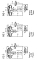
- a right position of the shift rod 9 is shown, which the shift rod assumes when the pressure control valve 7 the System pressure Psy in a first range A from 0 to 40% of the System pressure regulates. This is due to the first piston 3 the shift rod 9 applied force from the left greater than that Sum of the by the auxiliary piston 6 and the second piston 5 of force applied on the right. This causes the shift rod to move 9 to the right. As shown in Figure 2, the shift rod 9 pivots thereby about a pivot point S, so that one of the in a Weggasse left gear is inserted.
- four switching gates N1, N2, N3 and N4 are specified, which are each in planes parallel to the image plane shown are located.
- the position of the shift rod 9 is in a second control range B of the pressure control valve 7 shown.
- the second Control range B includes a pressure range from 41 to 59% of the system pressure Psy.
- the shift rod 9 is located in a neutral position in an axis X-X. In this neutral position the shift rod 9 can e.g. a lane change in the transmission respectively.
- a stop 12 which as a stop for the Auxiliary piston 6 is used.
- Area B of the pressure control valve 7 thus lies the auxiliary piston 6 always on the stop 12. Forms at the same time the auxiliary piston 6 a stop for the shift rod 9, so that the shift rod in the second area is always in the neutral position is positioned.
- the position of the shift rod 9 is in a third control range C of the pressure control valve 7 shown.
- the third Control range C includes a pressure range from 60 to 100% of the system pressure Psy.
- the Shift rod in the third area C pushed to the left so that it again pivots about the pivot point S. This makes one again Gear engaged in an alley of the transmission.
- the three control areas A, B, C of the pressure control valve 7 shown the control areas depending on the regulation of the current intensity I of the pressure control valve can be achieved.
- this will be on the shift rod 9 prevailing force balance, so that the Shift rod 9 is in a desired position.
- the first piston surface 2 to the second piston surface 4 have a ratio of 1 to 2 half pressure on the regulated by the pressure control valve 7 A balance of forces occurs on the piston side, so that the shift rod is in the neutral position.
- the auxiliary piston 6 is there at his stop 12 so that the ones he exercises Forces do not cause the shift rod to shift.
- the gear actuator can thus be used can be operated by a single pressure control valve 7.
- the clutch valve 8 only ensures that the gear actuator when closed Clutch is separated from the system pressure Psy, so that it is ensured that while driving with the clutch closed no forces from the gear actuator can act on the transmission. This can extend the life of the gear unit. Additional leakage is also prevented.
- the invention Gear actuator has a simple mechanical Execution compared to the state of the art, and required fewer components, which means less manufacturing effort, lower weight and improved reliability can be achieved. There are also savings on the electronics side, the wiring harness and the controller, there only one pressure control valve needs to be controlled.
- Figure 6 is a gear actuator according to a second embodiment of the present invention. Same or Functionally identical parts are identified by the same reference numerals as referred to in the first embodiment.
- the first Piston 3 to the second piston 5 an area ratio of 5: 9. Furthermore, the first piston 3 has an area ratio to the auxiliary piston 6 from 5: 2 to. If the pressure Psy on the first piston 3 is twice as large as that through the pressure control valve 7 in the line 14 regulated pressure for the second piston 5 and the auxiliary piston 6, the shift rod 9 moves from that in FIG. 6 position shown in the direction of arrow R, since the force F of the first piston with 100 N greater than the force F of the second piston with 90 N. However, the shift rod 9 is only up move to the neutral position X-X, because there the auxiliary piston 6 in is positioned in its extended position and at this position there is a balance of forces since the auxiliary piston 6 abuts his stop 12.
- the auxiliary piston 6 thus acts as a stop for the shift rod so that this is in the neutral position X-X is positioned.
- the shift rod 9 can thus at a defined Pressure controlled by the control characteristic of the pressure control valve 7 and be brought into the neutral position without sensors. That is, for finding the neutral position of the shift rod no sensor is necessary. If an additional one for security reasons Sensor is present to neutral can determine in the event of a failure of this sensor with the invention Gear actuator still found the neutral position become.
- the forces indicated in FIG. 6 are only examples.
- the working piston surfaces are 2 and 4 and the piston area of the auxiliary piston 6 corresponding to the inlet and outlet Dimensioning of the gear unit.
- Figure 7 is a gear actuator according to a third embodiment of the present invention. Same or functional same parts have the same reference numerals as referred to in the first and second embodiments.
- a common, double-acting piston 20 intended.
- the piston 20 has a first working piston surface 2 and a second piston surface 4.
- the second piston surface 4 is only half the size of the first piston area Second
- the piston 20 is fixed to the connecting rod 21 Shift rod 9 connected to the movement of the shift rod 9 as a function of that regulated by the pressure control valve 7 To define pressure.
- the first working piston surface 2 is connected via a line 13 directly applied to the system pressure Psy, while the second piston surface 4 via a line 14 with the through the pressure control valve 7 regulated system pressure is applied.
- the Gear actuator according to the invention according to the third embodiment thus further simplified and lighter in weight exhibit.
- Figure 7 is that to determine the neutral position auxiliary pistons used are not shown. Otherwise corresponds the principle of operation of the gear actuator described previously Embodiments, so that the description given there can be referred.
- the present invention relates to a gear actuator for loading and unloading gears in an automated Manual transmission.
- the gear actuator includes one first working piston surface 2, a second working piston surface 4, an auxiliary piston 6 and a pressure control valve 7.
- the pressure control valve 7 regulates the pressure for the second piston surface 4.
- the first piston surface 2 and the pressure control valve 7 are with system pressure Psy and the first piston surface 2 and the pressure regulating valve 7 are from a System pressure can be disconnected.
Landscapes
- Engineering & Computer Science (AREA)
- General Engineering & Computer Science (AREA)
- Mechanical Engineering (AREA)
- Gear-Shifting Mechanisms (AREA)
- Control Of Fluid Gearings (AREA)
Abstract
Description
- Figur 1
- ein schematischer Hydraulikschaltplan eines Gangaktuators gemäß einem ersten Ausführungsbeispiel der vorliegenden Erfindung,
- Figur 2
- eine schematische Ansicht des in Figur 1 gezeigten Gangaktuators in einem ersten geregelten Bereich,
- Figur 3
- eine schematische Ansicht des in Figur 1 gezeigten Gangaktuators in einem zweiten geregelten Bereich,
- Figur 4
- eine schematische Ansicht des in Figur 1 gezeigten Gangaktuators in einem dritten geregelten Bereich,
- Figur 5
- ein schematisches Diagramm, welches den durch das Druckregelventil geregelten Druck in Abhängigkeit von der Stromstärke darstellt,
- Figur 6
- eine schematische Ansicht eines Gangaktuators gemäß einem zweiten Ausführungsbeispiel der vorliegenden Erfindung,
- Figur 7
- eine schematische Ansicht eines Gangaktuators gemäß einem dritten Ausführungsbeispiel der vorliegenden Erfindung und
- Figur 8
- eine Ansicht eines Gangaktuators gemäß dem Stand der Technik.
Claims (14)
- Gangaktuator zum Einlegen und Auslegen von Gängen in einem automatisierten Handschaltgetriebe umfassend eine erste Arbeitskolbenfläche (2), eine zweite Arbeitskolbenfläche (4), einen Hilfskolben (6) und ein Druckregelventil (7), welches den Druck für die zweite Arbeitskolbenfläche (4) regelt, wobei die erste Arbeitskolbenfläche (2) und das Druckregelventil (7) mit einem Systemdruck (Psy) versorgt werden, und wobei die erste Arbeitskolbenfläche (2) und das Druckregelventil (7) über ein Absperrventil (8) vom Systemdruck (Psy) abkoppelbar sind.
- Gangaktuator nach Anspruch 1, dadurch gekennzeichnet, dass die erste Arbeitskolbenfläche (2) an einem ersten Arbeitskolben (3) ausgebildet ist und die zweite Arbeitskolbenfläche (4) an einem zweiten Arbeitskolben (5) ausgebildet ist.
- Gangaktuator nach Anspruch 1, dadurch gekennzeichnet, dass die erste Arbeitskolbenfläche (2) und die zweite Arbeitskolbenfläche (4) an einem gemeinsamen Arbeitskolben (20) ausgebildet sind.
- Gangaktuator nach einem der Ansprüche 1 bis 3, dadurch gekennzeichnet, dass das Druckregelventil (7) den Druck für den Hilfskolben (6) regelt.
- Gangaktuator nach einem der Ansprüche 1 bis 3, dadurch gekennzeichnet, dass der Hilfskolben (6) über das Absperrventil (8) mit Systemdruck versorgt wird.
- Gangaktuator nach einem der Ansprüche 1 bis 5, dadurch gekennzeichnet, dass der Hilfskolben (6) als Anschlag für eine Schaltstange (9) des Getriebes ausgebildet ist, um die Neutralstellung (X-X) der Schaltstange (9) festzulegen.
- Gangaktuator nach einem der Ansprüche 1 bis 6, dadurch gekennzeichnet, dass die erste und die zweite Arbeitskolbenfläche (2, 4) unterschiedlich groß sind.
- Gangaktuator nach Anspruch 7, dadurch gekennzeichnet, dass die erste Arbeitskolbenfläche (2) kleiner als die zweite Arbeitskolbenfläche (4) ist.
- Gangaktuator nach einem der Ansprüche 1 bis 8, dadurch gekennzeichnet, dass das Druckregelventil (7) die Druckhöhe des Systemdrucks in drei Bereichen regelt, wobei in einem ersten Bereich (A) ein Gang in einer Gasse (N1, N2, N3, N4) des Getriebes eingelegt wird, in einem zweiten Bereich (B) eine Neutralstellung (X-X) festgelegt ist und in einem dritten Bereich (C) ein anderer Gang in der Gasse eingelegt wird.
- Gangaktuator nach Anspruch 9, dadurch gekennzeichnet, dass im ersten Bereich (A) der Systemdruck auf 0% bis 40% des Systemdrucks geregelt ist.
- Gangaktuator nach Anspruch 9 oder 10 , dadurch gekennzeichnet, dass im zweiten Bereich (B) der Systemdruck auf 41% bis 59% des Systemdrucks geregelt ist.
- Gangaktuator nach einem der Ansprüche 9 bis 11, dadurch gekennzeichnet, dass im dritten Bereich (C) der Systemdruck auf 60% bis 100% des Systemdrucks geregelt ist.
- Gangaktuator nach einem der Ansprüche 1 bis 12, dadurch gekennzeichnet, dass das Absperrventil (8) als Kupplungsventil ausgebildet ist, welches auch einen Kupplungszylinder und einen Gassenaktuator (19) mit Systemdruck versorgt.
- Gangaktuator nach einem der Ansprüche 1 bis 13, gekennzeichnet durch einen Sensor zur Bestimmung der Position der Schaltstange (9).
Applications Claiming Priority (2)
| Application Number | Priority Date | Filing Date | Title |
|---|---|---|---|
| DE10110941 | 2001-03-07 | ||
| DE10110941A DE10110941C2 (de) | 2001-03-07 | 2001-03-07 | Gangaktuator zum Ein-/Auslegen von Gängen eines Getriebes |
Publications (3)
| Publication Number | Publication Date |
|---|---|
| EP1239195A2 true EP1239195A2 (de) | 2002-09-11 |
| EP1239195A3 EP1239195A3 (de) | 2005-04-13 |
| EP1239195B1 EP1239195B1 (de) | 2008-04-09 |
Family
ID=7676595
Family Applications (1)
| Application Number | Title | Priority Date | Filing Date |
|---|---|---|---|
| EP02005119A Expired - Lifetime EP1239195B1 (de) | 2001-03-07 | 2002-03-07 | Gangaktuator zum Ein/Auslegen von Gängen eines Getriebes |
Country Status (4)
| Country | Link |
|---|---|
| US (1) | US6723021B2 (de) |
| EP (1) | EP1239195B1 (de) |
| AT (1) | ATE391867T1 (de) |
| DE (2) | DE10110941C2 (de) |
Cited By (1)
| Publication number | Priority date | Publication date | Assignee | Title |
|---|---|---|---|---|
| CN103791077A (zh) * | 2012-10-30 | 2014-05-14 | 上海索达传动机械有限公司 | 一种变速箱后副箱保护系统的锁止机构 |
Families Citing this family (6)
| Publication number | Priority date | Publication date | Assignee | Title |
|---|---|---|---|---|
| US7924725B2 (en) | 2003-11-10 | 2011-04-12 | Nortel Networks Limited | Ethernet OAM performance management |
| DE502004001405D1 (de) * | 2003-11-28 | 2006-10-19 | Schaeffler Kg | Druckmittelbetätigte Schaltvorrichtung eines Stufenwechselgetriebes |
| DE102004037104A1 (de) * | 2004-07-30 | 2006-03-23 | Dr.Ing.H.C. F. Porsche Ag | Hydraulischer Linearantrieb, insbesondere hydraulischer Getriebeaktuator |
| DE102009045508A1 (de) * | 2009-10-09 | 2011-04-14 | Zf Friedrichshafen Ag | Getriebevorrichtung und Verfahren zum Betreiben einer Getriebevorrichtung |
| US8647078B2 (en) * | 2011-02-24 | 2014-02-11 | Ford Global Technologies, Llc | Motor pump assembly for transmission valve body |
| DE102011085900B4 (de) * | 2011-11-08 | 2017-06-29 | Bayerische Motoren Werke Aktiengesellschaft | Getriebe für Fahrzeuge |
Citations (1)
| Publication number | Priority date | Publication date | Assignee | Title |
|---|---|---|---|---|
| DE19931973A1 (de) | 1999-07-09 | 2001-01-11 | Wabco Gmbh & Co Ohg | Einrichtung zum Steuern einer Stelleinrichtung für ein Getriebe |
Family Cites Families (5)
| Publication number | Priority date | Publication date | Assignee | Title |
|---|---|---|---|---|
| DE4311868A1 (de) * | 1993-04-10 | 1994-10-13 | Hydraulik Ring Gmbh | Stellantrieb für Schaltgetriebe von Kraftfahrzeugen |
| GB9314951D0 (en) * | 1993-07-17 | 1993-09-01 | Prodrive Eng Ltd | Gear change mechanism |
| JPH10141499A (ja) * | 1996-11-15 | 1998-05-29 | Isuzu Motors Ltd | 4位置アクチュエータ及びこれを用いた自動変速機 |
| JPH11287321A (ja) * | 1998-04-01 | 1999-10-19 | Aisin Ai Co Ltd | 自動t/m用シフトアクチュエータの油圧回路 |
| DE10009505A1 (de) * | 2000-02-29 | 2001-08-30 | Hydraulik Ring Gmbh | Steuereinrichtung für automatisierte Schaltgetriebe von Fahrzeugen, vorzugsweise von Kraftfahrzeugen |
-
2001
- 2001-03-07 DE DE10110941A patent/DE10110941C2/de not_active Expired - Fee Related
-
2002
- 2002-03-07 EP EP02005119A patent/EP1239195B1/de not_active Expired - Lifetime
- 2002-03-07 AT AT02005119T patent/ATE391867T1/de not_active IP Right Cessation
- 2002-03-07 DE DE50212044T patent/DE50212044D1/de not_active Expired - Fee Related
- 2002-03-07 US US10/093,361 patent/US6723021B2/en not_active Expired - Fee Related
Patent Citations (1)
| Publication number | Priority date | Publication date | Assignee | Title |
|---|---|---|---|---|
| DE19931973A1 (de) | 1999-07-09 | 2001-01-11 | Wabco Gmbh & Co Ohg | Einrichtung zum Steuern einer Stelleinrichtung für ein Getriebe |
Cited By (2)
| Publication number | Priority date | Publication date | Assignee | Title |
|---|---|---|---|---|
| CN103791077A (zh) * | 2012-10-30 | 2014-05-14 | 上海索达传动机械有限公司 | 一种变速箱后副箱保护系统的锁止机构 |
| CN103791077B (zh) * | 2012-10-30 | 2016-03-30 | 上海索达传动机械有限公司 | 一种变速箱后副箱保护系统的锁止机构 |
Also Published As
| Publication number | Publication date |
|---|---|
| US6723021B2 (en) | 2004-04-20 |
| DE10110941A1 (de) | 2002-09-26 |
| DE50212044D1 (de) | 2008-05-21 |
| US20020173405A1 (en) | 2002-11-21 |
| DE10110941C2 (de) | 2003-06-12 |
| EP1239195B1 (de) | 2008-04-09 |
| EP1239195A3 (de) | 2005-04-13 |
| ATE391867T1 (de) | 2008-04-15 |
Similar Documents
| Publication | Publication Date | Title |
|---|---|---|
| DE10134115B4 (de) | Doppelkupplungsgetriebe eines Kraftfahrzeuges mit einem Hydraulikkreis und Verfahren zur hydraulischen Steuerung eines Doppelkupplungsgetriebes | |
| DE102007006354B4 (de) | Parksperrenanordnung für ein elektrisches Getriebebereichs-Auswahlsystem | |
| DE102004049050B4 (de) | Vorrichtung und Verfahren zum hydraulischen Steuern eines Kupplungsgetriebes | |
| EP1589262B1 (de) | Hydraulische Steuereinrichtung für ein Doppelkupplungsgetriebe sowie ein Verfahren zum hydraulischen Ansteuern eines Doppelkupplungsgetriebes. | |
| DE4320353A1 (de) | Hydraulische Getriebeansteuerung | |
| EP2360397A2 (de) | Verfahren zum Blockieren mindestens einer Anwahlposition eines Wählelements sowie Schalteinrichtung für Fahrzeuge | |
| DE10031181B4 (de) | Hydraulische Steuervorrichtung eines Automatikgetriebes | |
| DE102013101999A1 (de) | Bereichs-Schalteinrichtung | |
| DE69401847T2 (de) | Hydraulische Steuerung für Automatikgetriebe | |
| DE3011131C2 (de) | ||
| EP1239195B1 (de) | Gangaktuator zum Ein/Auslegen von Gängen eines Getriebes | |
| DE60116544T2 (de) | Schaltvorrichtung für ein Automatikgetriebe | |
| DE60304843T2 (de) | Getriebeschalteinrichtung | |
| DE10033811B4 (de) | Schalteinrichtung | |
| DE19541858A1 (de) | Gangschalt-Steuerungssystem eines Kfz-Automatikgetriebes | |
| DE10161338B4 (de) | Hydraulisches Steuerungssystem für Automatikgetriebe | |
| DE3836421A1 (de) | Elektrohydraulische steuereinrichtung | |
| DE2212679B2 (de) | Hydraulische Schaltvorrichtung für Lastschaltgetriebe mit Sicherung gegen Fehlschaltungen | |
| DE102017209414B4 (de) | Getriebevorrichtung für ein Kraftfahrzeug, Kraftfahrzeug und Verfahren zum Betreiben der Getriebevorrichtung | |
| EP1239194B1 (de) | Vorrichtung und Verfahren zur Gassenwahl bei einem Getriebe | |
| DE102013202272A1 (de) | Schalteinrichtung mit einer Schalt- und Wählwelle für ein Fahrzeuggetriebe | |
| DE102018133724A1 (de) | Elektronische getriebebereichsauswahl für ein stufenloses automatikgetriebe | |
| DE602004012539T2 (de) | Verfahren zur steuerung eines fahrzeuggetriebes | |
| DE10019776A1 (de) | Stufenwechselgetriebe | |
| DE102019205392B3 (de) | Manuelles Doppelkupplungsgetriebe für ein Kraftfahrzeug |
Legal Events
| Date | Code | Title | Description |
|---|---|---|---|
| PUAI | Public reference made under article 153(3) epc to a published international application that has entered the european phase |
Free format text: ORIGINAL CODE: 0009012 |
|
| AK | Designated contracting states |
Kind code of ref document: A2 Designated state(s): AT BE CH CY DE DK ES FI FR GB GR IE IT LI LU MC NL PT SE TR |
|
| AX | Request for extension of the european patent |
Free format text: AL;LT;LV;MK;RO;SI |
|
| PUAL | Search report despatched |
Free format text: ORIGINAL CODE: 0009013 |
|
| AK | Designated contracting states |
Kind code of ref document: A3 Designated state(s): AT BE CH CY DE DK ES FI FR GB GR IE IT LI LU MC NL PT SE TR |
|
| AX | Request for extension of the european patent |
Extension state: AL LT LV MK RO SI |
|
| 17P | Request for examination filed |
Effective date: 20050430 |
|
| 17Q | First examination report despatched |
Effective date: 20050706 |
|
| AKX | Designation fees paid |
Designated state(s): AT BE CH CY DE DK ES FI FR GB GR IE IT LI LU MC NL PT SE TR |
|
| GRAP | Despatch of communication of intention to grant a patent |
Free format text: ORIGINAL CODE: EPIDOSNIGR1 |
|
| RIC1 | Information provided on ipc code assigned before grant |
Ipc: F16H 61/30 20060101ALI20070913BHEP Ipc: F16H 61/28 20060101AFI20070913BHEP |
|
| GRAS | Grant fee paid |
Free format text: ORIGINAL CODE: EPIDOSNIGR3 |
|
| RAP1 | Party data changed (applicant data changed or rights of an application transferred) |
Owner name: HYDRAULIK-RING GMBH |
|
| GRAA | (expected) grant |
Free format text: ORIGINAL CODE: 0009210 |
|
| AK | Designated contracting states |
Kind code of ref document: B1 Designated state(s): AT BE CH CY DE DK ES FI FR GB GR IE IT LI LU MC NL PT SE TR |
|
| REG | Reference to a national code |
Ref country code: GB Ref legal event code: FG4D Free format text: NOT ENGLISH |
|
| REG | Reference to a national code |
Ref country code: CH Ref legal event code: EP |
|
| REG | Reference to a national code |
Ref country code: IE Ref legal event code: FG4D Free format text: LANGUAGE OF EP DOCUMENT: GERMAN |
|
| REF | Corresponds to: |
Ref document number: 50212044 Country of ref document: DE Date of ref document: 20080521 Kind code of ref document: P |
|
| NLV1 | Nl: lapsed or annulled due to failure to fulfill the requirements of art. 29p and 29m of the patents act | ||
| PG25 | Lapsed in a contracting state [announced via postgrant information from national office to epo] |
Ref country code: NL Free format text: LAPSE BECAUSE OF FAILURE TO SUBMIT A TRANSLATION OF THE DESCRIPTION OR TO PAY THE FEE WITHIN THE PRESCRIBED TIME-LIMIT Effective date: 20080409 Ref country code: ES Free format text: LAPSE BECAUSE OF FAILURE TO SUBMIT A TRANSLATION OF THE DESCRIPTION OR TO PAY THE FEE WITHIN THE PRESCRIBED TIME-LIMIT Effective date: 20080720 Ref country code: FI Free format text: LAPSE BECAUSE OF FAILURE TO SUBMIT A TRANSLATION OF THE DESCRIPTION OR TO PAY THE FEE WITHIN THE PRESCRIBED TIME-LIMIT Effective date: 20080409 Ref country code: PT Free format text: LAPSE BECAUSE OF FAILURE TO SUBMIT A TRANSLATION OF THE DESCRIPTION OR TO PAY THE FEE WITHIN THE PRESCRIBED TIME-LIMIT Effective date: 20080909 |
|
| REG | Reference to a national code |
Ref country code: IE Ref legal event code: FD4D |
|
| EN | Fr: translation not filed | ||
| PG25 | Lapsed in a contracting state [announced via postgrant information from national office to epo] |
Ref country code: SE Free format text: LAPSE BECAUSE OF FAILURE TO SUBMIT A TRANSLATION OF THE DESCRIPTION OR TO PAY THE FEE WITHIN THE PRESCRIBED TIME-LIMIT Effective date: 20080709 Ref country code: DK Free format text: LAPSE BECAUSE OF FAILURE TO SUBMIT A TRANSLATION OF THE DESCRIPTION OR TO PAY THE FEE WITHIN THE PRESCRIBED TIME-LIMIT Effective date: 20080409 Ref country code: IE Free format text: LAPSE BECAUSE OF FAILURE TO SUBMIT A TRANSLATION OF THE DESCRIPTION OR TO PAY THE FEE WITHIN THE PRESCRIBED TIME-LIMIT Effective date: 20080409 |
|
| PLBE | No opposition filed within time limit |
Free format text: ORIGINAL CODE: 0009261 |
|
| STAA | Information on the status of an ep patent application or granted ep patent |
Free format text: STATUS: NO OPPOSITION FILED WITHIN TIME LIMIT |
|
| 26N | No opposition filed |
Effective date: 20090112 |
|
| PG25 | Lapsed in a contracting state [announced via postgrant information from national office to epo] |
Ref country code: FR Free format text: LAPSE BECAUSE OF FAILURE TO SUBMIT A TRANSLATION OF THE DESCRIPTION OR TO PAY THE FEE WITHIN THE PRESCRIBED TIME-LIMIT Effective date: 20090130 |
|
| PG25 | Lapsed in a contracting state [announced via postgrant information from national office to epo] |
Ref country code: IT Free format text: LAPSE BECAUSE OF FAILURE TO SUBMIT A TRANSLATION OF THE DESCRIPTION OR TO PAY THE FEE WITHIN THE PRESCRIBED TIME-LIMIT Effective date: 20080409 |
|
| BERE | Be: lapsed |
Owner name: HYDRAULIK-RING G.M.B.H. Effective date: 20090331 |
|
| PG25 | Lapsed in a contracting state [announced via postgrant information from national office to epo] |
Ref country code: CY Free format text: LAPSE BECAUSE OF FAILURE TO SUBMIT A TRANSLATION OF THE DESCRIPTION OR TO PAY THE FEE WITHIN THE PRESCRIBED TIME-LIMIT Effective date: 20080409 |
|
| PG25 | Lapsed in a contracting state [announced via postgrant information from national office to epo] |
Ref country code: MC Free format text: LAPSE BECAUSE OF NON-PAYMENT OF DUE FEES Effective date: 20090331 |
|
| REG | Reference to a national code |
Ref country code: CH Ref legal event code: PL |
|
| GBPC | Gb: european patent ceased through non-payment of renewal fee |
Effective date: 20090307 |
|
| PG25 | Lapsed in a contracting state [announced via postgrant information from national office to epo] |
Ref country code: CH Free format text: LAPSE BECAUSE OF NON-PAYMENT OF DUE FEES Effective date: 20090331 Ref country code: LI Free format text: LAPSE BECAUSE OF NON-PAYMENT OF DUE FEES Effective date: 20090331 Ref country code: DE Free format text: LAPSE BECAUSE OF NON-PAYMENT OF DUE FEES Effective date: 20091001 |
|
| PG25 | Lapsed in a contracting state [announced via postgrant information from national office to epo] |
Ref country code: BE Free format text: LAPSE BECAUSE OF NON-PAYMENT OF DUE FEES Effective date: 20090331 |
|
| PG25 | Lapsed in a contracting state [announced via postgrant information from national office to epo] |
Ref country code: GB Free format text: LAPSE BECAUSE OF NON-PAYMENT OF DUE FEES Effective date: 20090307 |
|
| PG25 | Lapsed in a contracting state [announced via postgrant information from national office to epo] |
Ref country code: AT Free format text: LAPSE BECAUSE OF NON-PAYMENT OF DUE FEES Effective date: 20090307 |
|
| PG25 | Lapsed in a contracting state [announced via postgrant information from national office to epo] |
Ref country code: GR Free format text: LAPSE BECAUSE OF FAILURE TO SUBMIT A TRANSLATION OF THE DESCRIPTION OR TO PAY THE FEE WITHIN THE PRESCRIBED TIME-LIMIT Effective date: 20080710 |
|
| PG25 | Lapsed in a contracting state [announced via postgrant information from national office to epo] |
Ref country code: LU Free format text: LAPSE BECAUSE OF NON-PAYMENT OF DUE FEES Effective date: 20090307 |
|
| PG25 | Lapsed in a contracting state [announced via postgrant information from national office to epo] |
Ref country code: TR Free format text: LAPSE BECAUSE OF FAILURE TO SUBMIT A TRANSLATION OF THE DESCRIPTION OR TO PAY THE FEE WITHIN THE PRESCRIBED TIME-LIMIT Effective date: 20080409 |